EP0085860A1 - Device for exploiting heat energy from solar radiation impinging on a roof - Google Patents
Device for exploiting heat energy from solar radiation impinging on a roof Download PDFInfo
- Publication number
- EP0085860A1 EP0085860A1 EP83100445A EP83100445A EP0085860A1 EP 0085860 A1 EP0085860 A1 EP 0085860A1 EP 83100445 A EP83100445 A EP 83100445A EP 83100445 A EP83100445 A EP 83100445A EP 0085860 A1 EP0085860 A1 EP 0085860A1
- Authority
- EP
- European Patent Office
- Prior art keywords
- roof
- ridge
- profile
- translucent cover
- eaves
- Prior art date
- Legal status (The legal status is an assumption and is not a legal conclusion. Google has not performed a legal analysis and makes no representation as to the accuracy of the status listed.)
- Withdrawn
Links
Images
Classifications
-
- F—MECHANICAL ENGINEERING; LIGHTING; HEATING; WEAPONS; BLASTING
- F24—HEATING; RANGES; VENTILATING
- F24S—SOLAR HEAT COLLECTORS; SOLAR HEAT SYSTEMS
- F24S80/00—Details, accessories or component parts of solar heat collectors not provided for in groups F24S10/00-F24S70/00
- F24S80/50—Elements for transmitting incoming solar rays and preventing outgoing heat radiation; Transparent coverings
-
- F—MECHANICAL ENGINEERING; LIGHTING; HEATING; WEAPONS; BLASTING
- F24—HEATING; RANGES; VENTILATING
- F24S—SOLAR HEAT COLLECTORS; SOLAR HEAT SYSTEMS
- F24S10/00—Solar heat collectors using working fluids
- F24S10/70—Solar heat collectors using working fluids the working fluids being conveyed through tubular absorbing conduits
- F24S10/75—Solar heat collectors using working fluids the working fluids being conveyed through tubular absorbing conduits with enlarged surfaces, e.g. with protrusions or corrugations
- F24S10/755—Solar heat collectors using working fluids the working fluids being conveyed through tubular absorbing conduits with enlarged surfaces, e.g. with protrusions or corrugations the conduits being otherwise bent, e.g. zig-zag
-
- F—MECHANICAL ENGINEERING; LIGHTING; HEATING; WEAPONS; BLASTING
- F24—HEATING; RANGES; VENTILATING
- F24S—SOLAR HEAT COLLECTORS; SOLAR HEAT SYSTEMS
- F24S20/00—Solar heat collectors specially adapted for particular uses or environments
- F24S20/60—Solar heat collectors integrated in fixed constructions, e.g. in buildings
- F24S20/67—Solar heat collectors integrated in fixed constructions, e.g. in buildings in the form of roof constructions
-
- Y—GENERAL TAGGING OF NEW TECHNOLOGICAL DEVELOPMENTS; GENERAL TAGGING OF CROSS-SECTIONAL TECHNOLOGIES SPANNING OVER SEVERAL SECTIONS OF THE IPC; TECHNICAL SUBJECTS COVERED BY FORMER USPC CROSS-REFERENCE ART COLLECTIONS [XRACs] AND DIGESTS
- Y02—TECHNOLOGIES OR APPLICATIONS FOR MITIGATION OR ADAPTATION AGAINST CLIMATE CHANGE
- Y02A—TECHNOLOGIES FOR ADAPTATION TO CLIMATE CHANGE
- Y02A30/00—Adapting or protecting infrastructure or their operation
- Y02A30/60—Planning or developing urban green infrastructure
-
- Y—GENERAL TAGGING OF NEW TECHNOLOGICAL DEVELOPMENTS; GENERAL TAGGING OF CROSS-SECTIONAL TECHNOLOGIES SPANNING OVER SEVERAL SECTIONS OF THE IPC; TECHNICAL SUBJECTS COVERED BY FORMER USPC CROSS-REFERENCE ART COLLECTIONS [XRACs] AND DIGESTS
- Y02—TECHNOLOGIES OR APPLICATIONS FOR MITIGATION OR ADAPTATION AGAINST CLIMATE CHANGE
- Y02B—CLIMATE CHANGE MITIGATION TECHNOLOGIES RELATED TO BUILDINGS, e.g. HOUSING, HOUSE APPLIANCES OR RELATED END-USER APPLICATIONS
- Y02B10/00—Integration of renewable energy sources in buildings
- Y02B10/20—Solar thermal
-
- Y—GENERAL TAGGING OF NEW TECHNOLOGICAL DEVELOPMENTS; GENERAL TAGGING OF CROSS-SECTIONAL TECHNOLOGIES SPANNING OVER SEVERAL SECTIONS OF THE IPC; TECHNICAL SUBJECTS COVERED BY FORMER USPC CROSS-REFERENCE ART COLLECTIONS [XRACs] AND DIGESTS
- Y02—TECHNOLOGIES OR APPLICATIONS FOR MITIGATION OR ADAPTATION AGAINST CLIMATE CHANGE
- Y02E—REDUCTION OF GREENHOUSE GAS [GHG] EMISSIONS, RELATED TO ENERGY GENERATION, TRANSMISSION OR DISTRIBUTION
- Y02E10/00—Energy generation through renewable energy sources
- Y02E10/40—Solar thermal energy, e.g. solar towers
- Y02E10/44—Heat exchange systems
Definitions
- the invention relates to a device for obtaining thermal energy from solar radiation falling on a roof according to the preamble of claim 1.
- Such a device has the advantage that it can be installed completely independently of the position of the rafters, since their installation only begins above the existing roof formwork, possibly with roofing felt laid thereon. The installation of such a device can therefore be carried out over a very large area, i.e. the entire roof can be designed as a single collector without subdivision.
- the drawing of DE-OS 28 56 052 shows a device according to the preamble of claim 1.
- the heat-insulating underlayer is formed from an insulating compound in a profiled sheet metal and from insulating plates arranged thereon.
- the two side edges of each sheet of translucent cover running from the ridge to the eaves rest on a beam running from the ridge to the eaves.
- Two adjacent beams are arranged on a plank that extends from the ridge to the eaves between the individual insulation panels and is fastened to the profiled sheet.
- the individual sheets of the translucent cover are spaced apart.
- a rain gutter running from the ridge to the eaves is provided on each of the planks below the gap.
- the liquid-carrying pipes run parallel to the gutters on the planks, that is, from the ridge to the eaves.
- a collecting tube must therefore be provided at the ridge-side end and at the eaves-side end of the tubes. This means that a weld connection must be created between each pipe running from the ridge to the eaves and the collecting pipe on the ridge and eaves side.
- the numerous welded connections increase the risk of leaks due to faulty welds.
- the pipe system welded together in this way is also rigid and is therefore not able to absorb large stresses, such as can occur as a result of high temperature fluctuations.
- the residence time of the liquid in the tubes between the two header tubes is also relatively short, so that the heat transfer between the collector plate and the liquid in the tubes leaves something to be desired.
- the invention as characterized in the claims, is based on the object, the efficiency and the reliability of a device as in the Oberbe handle of claim 1 is outlined, without increasing, at least without significant additional material and assembly costs.
- the individual sheets of the translucent cover can be attached to the beams on the roof formwork with a clamping profile device according to DE-GM 81 26 507.7. Their width can be varied as required. They can also be adapted to any roof shape. Polycarbonate hollow sheets are particularly suitable as a translucent cover. These are supplied with a width of one meter and a length of 12 meters. The problem of sealing, which is difficult to solve, does not arise with the device according to the invention.
- the collector plate is preferably coated with solar paint.
- the coils (preferably made of copper) can be made independently of the roof construction, i.e. the rafter spacing, etc., must be laid out over the entire roof. This brings further cost savings during installation and decisive advantages when sealing the pipe connections.
- the pipe coils can also move without damage in the event of temperature fluctuations.
- the roof can also be designed for hot air operation.
- an opening for air access is provided on an eaves-side end of an end face of the roof and an opening for the warm air outlet is provided on the opposite end side.
- an air / water heat exchanger can then be installed if instead of a hot air heating system such as hot water is required, or if hot domestic water is used at the same time should be processed.
- a hot air heating system such as hot water is required, or if hot domestic water is used at the same time should be processed.
- the air outlet opening is connected to the air inlet opening via an air connection channel.
- the air circulation takes place by means of a fan provided in the air connection duct.
- the gable roof shown in the drawing consists of rafters .3 which run from the ridge 1 to the eaves 2 and which rest on the ridge purlin 4 and the foot purlin 5.
- 6 is a pair of pliers on which the ridge purlin 4 rests.
- the roof formwork 7 consisting of individual boards is nailed to the outside of the rafters 3, to which the roofing felt 8 is applied as a sealing roof covering.
- the roof corresponds to the roof construction that is almost exclusively implemented nowadays, especially in multi-family and single-family houses.
- a thermally insulating underlayer 9, for example made of rock wool panels, is now applied to the roofing felt 8. Furthermore, in the direction from the ridge 1 to the eaves 2 extending boards 10 and at the first and first end of the roof parallel to the ridge 1 extending boards 11, 11 are laid on the roofing felt 8 or the roof formwork 7 and fastened thereon.
- the boards 10 . 11 can be impregnated against fire and putrefaction.
- the coated black collector plate 12 / preferably made of aluminum, is applied to the roof in large lengths.
- the individual tracks of the collector plate. 12 are mutually sealed with heat-resistant sealing tapes.
- the sheet size of the K ollektorblechbahnen 12 may be, for example, 6 x 1 m.
- the beams 13 and 14 and 15 are fastened, for example, to the underlying roof formwork 7 by means of frame screws 16, the heads of which are countersunk in recesses 17 in the beams 13, 14 and 15.
- stiffening profiles 18 running parallel to the ridge, which are embedded in the beams 13 running from the ridge 1 to the eaves 2.
- the stiffening profiles 18 are preferably T-profiles, for example made of aluminum or galvanized steel. Their number depends on the expected snow and wind pressure that acts on the roof.
- the bars 13 extending from the ridge 1 to the eaves 2 are arranged at a distance from the bars 15 and 14 running parallel to the ridge 1 at the eaves and ridge-side roof ends, forming channels 19 and 20, respectively.
- the channels 19 and 20 are also bridged by preferably T-profiles 21 made of aluminum or galvanized steel, which are screwed into the beams 13 which extend in the direction from the ridge 1 to the eaves 2 (FIG. 1).
- the translucent cover 22 is laid, which preferably consists of hollow polycarbonate sheets.
- the cover or the hollow plates 22 can be fastened with the clamping profile device 23 shown in FIG vertical leg of the T-profile 25 sliding U-profile 26 with flanges 27, 28 at its opening facing downwards and a rubber profile 29 arranged between the profiles 25 and 26, the flanges 27, 28 engaging over the adjacent edge of the cover or the adjacent hollow plates 22.
- the clamping profile device 23 is explained in DE-GM 81 26 507.7.
- a supply air distribution duct 30 and a warm air collecting duct 31 run under the roof on each side of the gable roof.
- an air inlet opening 32 leads from the supply air distribution duct 30 into the cavity between the collector plate 12 and the cover 22.
- the air supplied via the air inlet opening 32 flows through the duct 19 and between the beams 13 to the ridge 1 and from there through the duct 20 to an air outlet opening 33, from where it is sucked into the warm air collecting duct 31.
- the air dissipates the solar energy absorbed by the collector plate 12 as heat.
- copper pipe coils 34 can be arranged in the beads of the collector plate 12, the beads being formed in the collector plate 12 before it is laid and the pipe coils 34 being laid in the beads before the cover 22 is installed.
- a heat exchanger (not shown in the drawing) can also be connected downstream of the air outlet opening 33. Instead of process water, another liquid can also be heated, which is supplied, for example, to a heater in which the heat is stored in heat storage masses (for example the ground) for later removal.
- a ridge cap 35 extends over the wedge-shaped Space between the ridge-side beams 13 extending parallel to the ridge 1 on both sides of the gable.
- a A connecting plate 36 is provided on the front formwork 37.
- passages 38 are provided in the beam 15 at the end of the eaves.
- the collector plate 12 extends from the heat-insulating lower layer 9 on the inside of the beams 15 (and 14) and 13 upwards.
- the beams 13, 14 and 15 are provided with a sealing layer 39; likewise, a sealing layer 40 is provided between the T-profiles 18, 21 and the cover 22, as can be seen in particular from FIG. 4.
- a U-profile 41 engages over the eaves-side end of the cover 22 (FIG. 3).
Landscapes
- Engineering & Computer Science (AREA)
- Chemical & Material Sciences (AREA)
- Physics & Mathematics (AREA)
- Life Sciences & Earth Sciences (AREA)
- Sustainable Development (AREA)
- Sustainable Energy (AREA)
- Thermal Sciences (AREA)
- Combustion & Propulsion (AREA)
- Mechanical Engineering (AREA)
- General Engineering & Computer Science (AREA)
- Dispersion Chemistry (AREA)
- Building Environments (AREA)
Abstract
Description
Die Erfindung bezieht sich auf eine Einrichtung zur Gewinnung von Wärmeenergie aus auf ein Dach fallender Sonnenstrahlung nach dem Oberbegriff des Anspruchs 1.The invention relates to a device for obtaining thermal energy from solar radiation falling on a roof according to the preamble of
Eine derartige Einrichtung hat den Vorteil, daß sie völlig unabhängig von der Lage der Dachsparren installiert werden kann, da ihre Installation erst oberhalb der vorhandenen Dachschalung , gegebenenfalls mit darauf verlegter Dachpappe beginnt. Die Montage einer solchen Einrichtung kann also sehr großflächig ausgeführt werden, d.h. das gesamte Dach läßt sich ohne Unterteilung als ein einziger Kollektor auslegen.Such a device has the advantage that it can be installed completely independently of the position of the rafters, since their installation only begins above the existing roof formwork, possibly with roofing felt laid thereon. The installation of such a device can therefore be carried out over a very large area, i.e. the entire roof can be designed as a single collector without subdivision.
Der Zeichnung der DE-OS 28 56 052 läßt sich eine Einrichtung nach dem Oberbegriff des Anspruches 1 entnehmen. Dabei ist die wärmeisolierende Unterschicht aus einer Isoliermasse in einem profilierten Blech sowie aus darauf angeordneten Isolierplatten gebildet. Die beiden Seitenkanten jeder vom First zur Traufe verlaufenden Bahn der lichtdurchlässigen Abdeckung liegen auf jeweils einem vom First zur Traufe verlaufenden Balken auf. Je zwei benachbarte Balken sind auf einem Bohlen angeordnet, der sich zwischen den einzelnen Isolierplatten vom First zur Traufe erstreckt und auf dem profilierten Blech befestigt ist.The drawing of DE-OS 28 56 052 shows a device according to the preamble of
Die einzelnen Bahnen der lichtdurchlässigen Abdeckung sind im Abstand voneinander angeordnet. Um zu verhindern, daß der Niederschlag, der in den Spalt zwischen einander benachbarten Bahnen der lichtdurchlässigen Abdeckung eindringt, zu wärmeisolierenden Unterschicht gelangt, ist auf jeder der Bohlen unterhalb des Spalts eine vom First zur Traufe verlaufende Regenrinne vorgesehen.The individual sheets of the translucent cover are spaced apart. In order to prevent the precipitation, which penetrates into the gap between adjacent sheets of the translucent cover, from reaching the heat-insulating underlayer, a rain gutter running from the ridge to the eaves is provided on each of the planks below the gap.
Durch den Spalt zwischen den einzelnen Bahnen der lichtdurchlässigen Abdeckung entweicht jedoch ein großer Teil der durch das Kollektorblech aufgeheizten Luft nach außen, so daß das Kollektorblech und damit die Flüssigkeit in den Rohren nur unzureichend erwärmt wird. Hinzu kommt, daß sich die Luftfeuchtigkeit der Atmosphäre, die durch den Spalt zwischen den einzelnen Bahnen eindringt, in der wärmeisolierenden Unterschicht und an der lichtdurchlässigen Abdeckung niederschlagen kann. Da sie kaum entfernbar ist, sammelt sie sich in der wärmeisolierenden Unterschicht an, wodurch deren Isolierwirkung stark beeinträchtigt bzw. fast völlig beseitigt wird. Das Beschlagen der lichtdurchlässigen Abdeckung-hat eine entsprechende Verminderung des Durchgangs der Sonnenstrahlung zur Folge.However, a large part escapes through the gap between the individual sheets of the translucent cover the air heated by the collector plate to the outside, so that the collector plate and thus the liquid in the tubes is not heated sufficiently. In addition, the atmospheric humidity, which penetrates through the gap between the individual webs, can be reflected in the heat-insulating lower layer and on the translucent cover. Since it can hardly be removed, it accumulates in the heat-insulating underlayer, which greatly impairs or almost completely eliminates its insulating effect. Fogging the translucent cover results in a corresponding reduction in the passage of solar radiation.
Weiterhin verlaufen bei der Einrichtung nach der DE-OS 28 56 052 die Flüssigkeit führenden Rohre parallel zu den Regenrinnen auf den Bohlen, also vom First zur Traufe. Am firstseitigen Ende und am traufenseitigen Ende der Rohre muß also jeweils ein Sammelrohr vorgesehen sein. Das heißt, zwischen jedem vom First zur Traufe verlaufenden Rohr und dem first- sowie traufenseitigen Sammelrohr muß jeweils eine Schweißverbindung geschaffen werden. Abgesehen von dem erheblichen Arbeitsaufwand , wird durch die zahlreichen Schweißverbindungen die Gefahr von Undichtigkeiten durch fehlerhafte Schweißstellen entsprechend erhöht. Auch ist das so zusammengeschweißte Rohrsystem starr und daher nicht in der Lage, große Spannungen, wie sie durch hohe Temperaturschwankungen auftreten können, aufzunehmen. Auch ist die Verweilzeit der Flüssigkeit in den Rohren zwischen den beiden Sammelrohren verhältnismäßig kurz, so daß der Wärmeübergang zwischen dem Kollektorblech und der Flüssigkeit in den Rohren zu Wünschen übrig läßt.Furthermore, in the device according to DE-OS 28 56 052, the liquid-carrying pipes run parallel to the gutters on the planks, that is, from the ridge to the eaves. A collecting tube must therefore be provided at the ridge-side end and at the eaves-side end of the tubes. This means that a weld connection must be created between each pipe running from the ridge to the eaves and the collecting pipe on the ridge and eaves side. In addition to the considerable amount of work involved, the numerous welded connections increase the risk of leaks due to faulty welds. The pipe system welded together in this way is also rigid and is therefore not able to absorb large stresses, such as can occur as a result of high temperature fluctuations. The residence time of the liquid in the tubes between the two header tubes is also relatively short, so that the heat transfer between the collector plate and the liquid in the tubes leaves something to be desired.
Der Erfindung, wie sie in den Ansprüchen gekennzeichnet ist, liegt die Aufgabe zugrunde, den Wirkungsgrad und die Zuverlässigkeit einer Einrichtung, wie sie im Oberbegriff des Anspruchs 1 umrissen ist, ohne, jedenfalls ohne nennenswerte zusätzliche Material- und Montagekosten zu erhöhen.The invention, as characterized in the claims, is based on the object, the efficiency and the reliability of a device as in the Oberbe handle of
Die einzelnen Bahnen der lichtdurchlässigen Abdeckung können mit einer Klemmprofilvorrichtung gemäß dem DE-GM 81 26 507.7 auf den Balken auf der Dachschalung befestigt werden. Ihre Breite kann je nach Bedarf variiert werden. Auch können sie an jede Dachform angepaßt werden. Als lichtdurchlässige Abdeckung eignen sich insbesondere Polycarbonat-Hohlplatten. Diese werden mit einer Breite von einem Meter und einer Länge von 12 Metern geliefert. Die schwer lösbare Abdichtungsfrage stellt sich bei der erfindungsgemäßen Einrichtung also nicht.The individual sheets of the translucent cover can be attached to the beams on the roof formwork with a clamping profile device according to DE-GM 81 26 507.7. Their width can be varied as required. They can also be adapted to any roof shape. Polycarbonate hollow sheets are particularly suitable as a translucent cover. These are supplied with a width of one meter and a length of 12 meters. The problem of sealing, which is difficult to solve, does not arise with the device according to the invention.
Das Kollektorblech ist vorzugsweise mit Solarlack beschichtet.The collector plate is preferably coated with solar paint.
Die Rohrschlangen (vorzugsweise aus Kupfer) können unabhängig von der Dachkonstruktion, d.h. dem Dachsparrenabstand usw., über das gesamte Dach ausgelegt werden. Dies bringt eine weitere Kosteneinsparung bei der Installation und entscheidende Vorteile bei der Abdichtung der Rohrverbindungen mit sich. Auch können sich die Rohrschlangen bei Temperaturschwankungen ohne Schaden bewegen.The coils (preferably made of copper) can be made independently of the roof construction, i.e. the rafter spacing, etc., must be laid out over the entire roof. This brings further cost savings during installation and decisive advantages when sealing the pipe connections. The pipe coils can also move without damage in the event of temperature fluctuations.
Das Dach kann erfindungsgemäß auch für den Warmluftbetrieb ausgelegt werden. Dafür wird an einem traufenseitigen Ende einer Stirnseite des Dachs eine Öffnung für den Luft- - zutritt und an der gegenüberliegenden Stirnseite firstseitig eine öffnung für den Warmluftaustritt vorgesehen. Unmittelbar nach der Luftaustrittsöffnung kann sodann ein Luft/Wasser-Wärmeaustauscher installiert werden, wenn statt einer Warmluftheizung eine solche mit Warmwasser gewünscht wird, bzw. wenn gleichzeitig warmes Brauchwasser aufbereitet werden soll. Zur Bildung eines geschlossenen Luftkreislaufs ist die Luftaustrittsöffnung mit der Lufteintrittsöffnung über einen Luftverbindungskanal verbunden. Die Luftumwälzung erfolgt mittels eines in dem Luftverbindungskanal vorgesehenen Ventilators.According to the invention, the roof can also be designed for hot air operation. For this purpose, an opening for air access is provided on an eaves-side end of an end face of the roof and an opening for the warm air outlet is provided on the opposite end side. Immediately after the air outlet opening, an air / water heat exchanger can then be installed if instead of a hot air heating system such as hot water is required, or if hot domestic water is used at the same time should be processed. To form a closed L uftkreislaufs the air outlet opening is connected to the air inlet opening via an air connection channel. The air circulation takes place by means of a fan provided in the air connection duct.
Als besonders leistungsfähig ist diejenige Ausführungsform der erfindungsgemäßen Einrichtung anzusehen, bei der sowohl ein Flüssigkeitsbetrieb als auch ein Warmluftbetrieb vorgesehen ist.The embodiment of the device according to the invention in which both liquid operation and warm air operation are provided are to be regarded as particularly powerful.
Nachstehend ist eine Ausführungsform der Erfindung anhand der beigefügten Zeichnung beschrieben. Es zeigen:
Figur 1 eine perspektivische Ansicht eines Dachs mit der erfindungsgemäen Einrichtung, wobei die lichtdurchlässige Abdeckung teilweise entfernt worden ist;Figur 2 einen Querschnitt durch das Dach gemäßFigur 1, wobei die Wärmeaustauschrohrschlangen weggelassen sind;Figur 3 eine Ansicht des traufenseitigen Endes des Dachs gemäßFigur 2 in vergrößerter Wiedergabe; undFigur 4 einen Schnitt durch das Dach parallel zum First an einer Dachstirnseite in vergrößerter Wiedergabe.
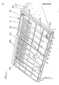
- Figure 1 is a perspective view of a roof with the inventive device, the translucent cover has been partially removed;
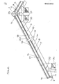
- FIG. 2 shows a cross section through the roof according to FIG. 1, the heat exchange tube coils being omitted;
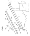
- 3 shows a view of the eaves-side end of the roof according to FIG. 2 in an enlarged representation; and
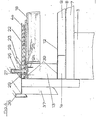
- Figure 4 shows a section through the roof parallel to the ridge on a roof end in an enlarged representation.
Das in der Zeichnung dargestellte Giebeldach besteht aus vom First 1 zur Traufe 2 verlaufenden Dachsparren .3, die auf der Firstpfette 4 und der Fußpfette 5 aufliegen. Mit 6 ist eine Zange bezeichnet, auf der die Firstpfette 4 aufliegt. Auf die Dachsparren 3 ist außen die aus einzelnen Brettern bestehende Dachschalung 7 aufgenagelt, auf die die Dachpappe 8 als abdichtende Dachabdeckung aufgebracht ist. Insoweit entspricht das Dach also der heutzutage insbesondere bei Mehr- und Einfamilienhäusern fast ausnahmslos verwirklichten Dachkonstruktion.The gable roof shown in the drawing consists of rafters .3 which run from the
Erfindungsgemäß ist nun auf die Dachpappe 8 eine wärmeisolierende Unterschicht 9, beispielsweise aus Steinwollplatten, aufgebracht. Ferner sind in Richtung vom First 1 zur Traufe 2 verlaufende Bretter 10 sowie am Eraufen- und firstseitigen Ende des Dachs parallel zum First 1 verlaufende Bretter 11, 11 auf der Dachpappe 8 bzw. der Dachschalung 7 verlegt und darauf befestigt. Die Bretter 10. 11 können gegen Brand- und Fäulnisbildung imprägniert sein.According to the invention, a thermally insulating
Alsdann ist in großen Bahnen das beschichtete schwarze Kollektorblech 12/vorzugsweise aus Aluminium, auf das Dach aufgebracht. Die einzelnen Bahnen des Kollektorblechs. 12 sind mit hitzefesten Abdichtbändern gegenseitig abgedichtet. Die Bahngröße der Kollektorblechbahnen 12 kann beispielsweise 6 x 1 m betragen.Then the coated
Auf dem Kollektorblech 12 sind nun gegenüber den Brettern 10 bzw. 11 und 11 in Richtung vom First 1 zur Traufe 2 verlaufende Vierkantbalken 13 bzw. am first- und traufenseitigen Dachende parallel zum First 1 verlaufende Vierkantbalken 14, 15 angeordnet.On the
Die Balken 13 sowie 14 und 15 werden beispielsweise mittels Gestellschrauben 16, deren Köpfe in Ausnehmungen 17 in den Balken 13, 14 und 15 versenkt sind, auf der darunterliegenden Dachschalung 7 befestigt.The
Anschließend erfolgt eine Verlegung von parallel zum First verlaufenden Versteifungsprofilen 18, die in die vom First 1 zur Traufe 2 verlaufenden Balken 13 eingelassen sind. Die Versteifungsprofile 18 sind vorzugsweise T-Profile, beispielsweise aus Aluminium oder verzinktem Stahl. Ihre Anzahl richtet sich nach dem zu erwartenden Schnee- und Winddruck, der auf das Dach einwirkt.Then there is a laying of
Die vom First 1 zur Traufe 2 verlaufenden Balken 13 sind mit Abstand von den am traufe- und am firstseitigen Dachende parallel zum First 1 verlaufenden Balken 15 bzw. 14 unter Bildung von Kanälen 19 bzw. 20 angeordnet. Die Kanäle 19 und 20 werden gleichfalls von vorzugsweise T-Profilen 21 aus Aluminium oder verzinktem Stahl überbrückt, die in die sich in Richtung vom First 1 zur Traufe 2 erstreckenden Balken 13 angeschraubt werden.(Fig. 1).The
Anschließend wird die lichtdurchlässige Abdeckung 22 verlegt, die vorzugsweise aus Polycarbonat-Hohlplatten besteht.Then the
Die Befestigung der Abdeckung bzw. der Hohlplatten 22 kann mit in der in Figur 4 dargestellten Klemmprofilvorrichtung 23 erfolgen, die aus einem auf einen sich in Richtung vom First 1 zur Traufe 2 erstreckenden Balken 13 mittels Schrauben 24 befestigten T-Profil 25, einem über den senkrechten Schenkel des T-Profils 25 schiebbaren U-Profil 26 mit Flanschen 27, 28 an seiner nach unten gekehrten öffnung und einem zwischen den Profilen 25 und 26 angeordneten Gummiprofil 29 besteht, wobei die Flansche 27, 28 dem benachbarten Rand der Abdeckung bzw. der benachbarten Hohlplatten 22 übergreifen. Die Klemmprofilvorrichtung 23 ist in der DE-GM 81 26 507.7 näher erläutert.The cover or the
Gemäß Figur 2 verlaufen unter dem Dach auf jeder Seite des Giebeldaches ein Zuluftverteilerkanal 30 sowie ein Warmluftsammelkanal 31.According to FIG. 2, a supply
Vom Zuluftverteilerkanal 30 führt am unteren stirnseitigen Dachende eine Lufteintrittsöffnung 32 inden Hohlraum zwischen dem Kollektorblech 12 und der Abdeckung 22. Die über die Lufteintrittsöffnung 32 zugeführte Luft strömt durch den Kanal 19 und zwischen den Balken 13 zum First 1 und gelangt von dort durch den Kanal 20 zu einer Luftaustrittsöffnung 33, von wo sie in den Warmluftsammelkanal 31 gesaugt wird. Auf ihrem Weg von der Lufteintrittsöffnung 32 zu der Luftaustrittsöffnung 33 führt die Luft die von dem Kollektorblech 12 absorbierte Sonnenenergie als Wärme ab.At the lower end of the roof, an air inlet opening 32 leads from the supply
Um warmes Brauchwasser zu erzeugen, können Kupferrohrschlangen 34 in Sicken des Kollektorbleches 12 angeordnet sein, wobei die Sicken in dem Kollektorblech 12 vor dessen Verlegung ausgebildet werden und die Rohrschlangen 34 vor der Montage der Abdeckung 22 in den Sicken verlegt werden.In order to produce hot domestic water, copper pipe coils 34 can be arranged in the beads of the
Auch kann ein (in der Zeichnung nicht dargestellter) - Wärmeaustauscher der Luftaustrittsöffnung 33 nachgeschaltet sein. Statt Brauchwasser kann auch eine andere Flüssigkeit erwärmt werden, die beispielsweise einem Erhitzer zugeführt wird, in dem die Wärme in Wärmespeichermassen (beispielsweise dem Erdboden) für eine spätere Entnahme gespeichert wird.A heat exchanger (not shown in the drawing) can also be connected downstream of the
Eine Firstkappe 35 erstreckt sich über den keilförmigen Raum zwischen den firstseitigen, sich parallel zum First 1 erstreckenden Balken 13 beiderseits des Giebels.A
Ein Anschlußblech 36 ist auf der Stirnschalung 37 vorgesehen. Um eine Entwässerung des Hohlraums zwischen dem Kollektorblech 12 und der Abdeckung 22 zu gewährleisten, sind in dem Balken 15 am traufenseitigen Ende Durchlässe 38 vorgesehen.A A connecting
Wie aus Figur 3 und 4 ersichtlich, erstreckt sich das Kollektorblech 12 von der wärmeisolierenden Unterschicht 9 an der Innenseite der Balken 15 (und 14) sowie 13 nach oben.As can be seen from FIGS. 3 and 4, the
An ihrer Unterseite und ihrer Oberseite sind die Balken 13, 14 und 15 mit einer Dichtungsschicht 39 versehen; desgleichen ist zwischen den T-Profilen 18, 21 und der Abdeckung 22 eine Dichtungsschicht 40 vorgesehen, wie insbesondere aus Figur 4 ersichtlich.On their underside and top, the
Ein U-Profil 41 übergreift das traufenseitige Ende der Abdeckung 22 (Figur 3).A U-profile 41 engages over the eaves-side end of the cover 22 (FIG. 3).
Claims (3)
Applications Claiming Priority (2)
| Application Number | Priority Date | Filing Date | Title |
|---|---|---|---|
| DE19823201618 DE3201618A1 (en) | 1982-01-20 | 1982-01-20 | DEVICE FOR THE EXTRACTION OF HEAT ENERGY FROM A RADIANT OF RADIATION |
| DE3201618 | 1982-01-20 |
Publications (1)
| Publication Number | Publication Date |
|---|---|
| EP0085860A1 true EP0085860A1 (en) | 1983-08-17 |
Family
ID=6153464
Family Applications (1)
| Application Number | Title | Priority Date | Filing Date |
|---|---|---|---|
| EP83100445A Withdrawn EP0085860A1 (en) | 1982-01-20 | 1983-01-19 | Device for exploiting heat energy from solar radiation impinging on a roof |
Country Status (2)
| Country | Link |
|---|---|
| EP (1) | EP0085860A1 (en) |
| DE (1) | DE3201618A1 (en) |
Cited By (5)
| Publication number | Priority date | Publication date | Assignee | Title |
|---|---|---|---|---|
| DE19615228A1 (en) * | 1996-04-18 | 1997-10-23 | Otto Breitenbach | Roof, wall or facade mounted solar panel powered heating system |
| WO2008078084A2 (en) * | 2006-12-23 | 2008-07-03 | Peter Martin Broatch | Solar collectors |
| FR2974375A1 (en) * | 2011-04-20 | 2012-10-26 | Terreal | SYSTEM FOR RECOVERING SOLAR INPUTS ON A TRADITIONAL ROOFING ROOF |
| GB2498737A (en) * | 2012-01-24 | 2013-07-31 | Tony Camfield | Solar energy capture system |
| EP2653633A1 (en) * | 2012-04-18 | 2013-10-23 | Terreal | System of recovery of the solar contributions on a traditional inclined roof |
Families Citing this family (6)
| Publication number | Priority date | Publication date | Assignee | Title |
|---|---|---|---|---|
| DE29506798U1 (en) * | 1995-04-21 | 1995-06-29 | Nova Solar Gmbh | Kit for creating a roof using prefabricated roof elements with integrated large collectors |
| DE19736002B4 (en) * | 1997-08-19 | 2005-03-03 | Zdjelar Zvonko | Roof tiles vacuum collector |
| DE102005046471A1 (en) * | 2005-09-22 | 2007-04-05 | Thomas Jahn | Solar arrangement for positioning below a roof comprises solar tubes held using special holding clips with eyelets |
| DE102009059883A1 (en) | 2009-12-21 | 2011-06-22 | Robert Bosch GmbH, 70469 | Solar collector, facade element and method for operating a solar system |
| DE202011101229U1 (en) | 2011-05-28 | 2012-08-30 | Robert Bosch Gmbh | solar panel |
| US10547270B2 (en) | 2016-02-12 | 2020-01-28 | Solarcity Corporation | Building integrated photovoltaic roofing assemblies and associated systems and methods |
Citations (5)
| Publication number | Priority date | Publication date | Assignee | Title |
|---|---|---|---|---|
| DE2826832A1 (en) * | 1977-06-20 | 1979-01-04 | Hastwell | ROOF STRUCTURE FOR ROOFS EQUIPPED WITH SOLAR HEATERS |
| DE2809550A1 (en) * | 1978-03-06 | 1979-09-13 | Schaefer Werke Gmbh | Solar heat panel mounting - has perforated flanges for angling to accommodate different spacings between supporting rafters |
| US4263896A (en) * | 1978-01-10 | 1981-04-28 | Sunhouse, Incorporated | Solar panel |
| DE3000289A1 (en) * | 1980-01-05 | 1981-07-09 | Peter 4224 Hünxe Spielvogel | Solar and environmental heat extracting roof - has fluid in pipes underneath, with process reversible in snow, and normal exterior |
| DE8031975U1 (en) * | 1980-12-01 | 1981-12-10 | Piller, Michael, 8229 Piding | ABSORBER ROOF |
-
1982
- 1982-01-20 DE DE19823201618 patent/DE3201618A1/en not_active Ceased
-
1983
- 1983-01-19 EP EP83100445A patent/EP0085860A1/en not_active Withdrawn
Patent Citations (5)
| Publication number | Priority date | Publication date | Assignee | Title |
|---|---|---|---|---|
| DE2826832A1 (en) * | 1977-06-20 | 1979-01-04 | Hastwell | ROOF STRUCTURE FOR ROOFS EQUIPPED WITH SOLAR HEATERS |
| US4263896A (en) * | 1978-01-10 | 1981-04-28 | Sunhouse, Incorporated | Solar panel |
| DE2809550A1 (en) * | 1978-03-06 | 1979-09-13 | Schaefer Werke Gmbh | Solar heat panel mounting - has perforated flanges for angling to accommodate different spacings between supporting rafters |
| DE3000289A1 (en) * | 1980-01-05 | 1981-07-09 | Peter 4224 Hünxe Spielvogel | Solar and environmental heat extracting roof - has fluid in pipes underneath, with process reversible in snow, and normal exterior |
| DE8031975U1 (en) * | 1980-12-01 | 1981-12-10 | Piller, Michael, 8229 Piding | ABSORBER ROOF |
Cited By (10)
| Publication number | Priority date | Publication date | Assignee | Title |
|---|---|---|---|---|
| DE19615228A1 (en) * | 1996-04-18 | 1997-10-23 | Otto Breitenbach | Roof, wall or facade mounted solar panel powered heating system |
| DE19615228C2 (en) * | 1996-04-18 | 2001-02-22 | Otto Breitenbach | Solar energy absorber roof and solar energy absorber wall or facade |
| WO2008078084A2 (en) * | 2006-12-23 | 2008-07-03 | Peter Martin Broatch | Solar collectors |
| WO2008078084A3 (en) * | 2006-12-23 | 2008-12-24 | Peter Martin Broatch | Solar collectors |
| FR2974375A1 (en) * | 2011-04-20 | 2012-10-26 | Terreal | SYSTEM FOR RECOVERING SOLAR INPUTS ON A TRADITIONAL ROOFING ROOF |
| WO2012172214A1 (en) * | 2011-04-20 | 2012-12-20 | Terreal | System for collecting solar gain on a traditional sloping roof |
| GB2498737A (en) * | 2012-01-24 | 2013-07-31 | Tony Camfield | Solar energy capture system |
| GB2498737B (en) * | 2012-01-24 | 2017-04-19 | Future Energy Source Ltd | A solar energy capture system |
| EP2653633A1 (en) * | 2012-04-18 | 2013-10-23 | Terreal | System of recovery of the solar contributions on a traditional inclined roof |
| FR2989708A1 (en) * | 2012-04-18 | 2013-10-25 | Terreal | SYSTEM FOR RECOVERING SOLAR INPUTS ON A TRADITIONAL ROOFING ROOF |
Also Published As
| Publication number | Publication date |
|---|---|
| DE3201618A1 (en) | 1983-07-28 |
Similar Documents
| Publication | Publication Date | Title |
|---|---|---|
| US8137170B2 (en) | Radiant baffle/collector for roof construction and retrofit | |
| DE102007045889A1 (en) | Complete solar energy system for use on e.g. terrace, has channels and hollow profiles extending into air outlet/inlet duct, and ventilator arranged at duct and designed for sucking or supplying air to channels | |
| EP0085860A1 (en) | Device for exploiting heat energy from solar radiation impinging on a roof | |
| EP0000543B1 (en) | Construction set for climatised roofs or facades and its use as evaporator | |
| DE2702939A1 (en) | Sheet metal roof panels suitable for solar heating - have elongate S-section with curved edges fitting over connecting pipes carrying heat exchange medium | |
| EP1988227B1 (en) | Roof for buildings | |
| EP0964967B1 (en) | Roof element | |
| DE3006974C2 (en) | Energy roof | |
| DE3147124C2 (en) | Shell and tube heat exchanger | |
| DE102005049222A1 (en) | Roof cover for e.g. carports, has solar absorbers for hot water treatment, where entire surface of roof is designed such that it is convexly rounded, and includes beveling surfaces possessing different lengths and forming pent roof | |
| DE2702938A1 (en) | HEAT EXCHANGE DEVICE FOR BUILDINGS | |
| WO1998017880A1 (en) | Roof element | |
| EP0026808B1 (en) | Roof covering or façade lining and method for the manufacture of a panel for this roof covering or façade lining | |
| DE2913490A1 (en) | Solar radiation absorber roof - has extruded heat carrier feed pipe parallel to gutter, between upper and lower roof panel | |
| DE3019388A1 (en) | Solar heating system using walls or roof - has cladding panels clipped onto water circulating pipes supported by wall brackets | |
| DE102007031601A1 (en) | Structural building part for reacting to environmental influences to collect heat from the sun has a structural outer surface for sheathing a heat-insulated structural inner space against environmental influences | |
| DE3140235A1 (en) | Roof covering | |
| WO2024037897A1 (en) | Roof structure having photovoltaic modules | |
| DE2935001A1 (en) | Ribbed hooked metal roofing or cladding panels - have fluid absorbing solar energy in channels between ribs | |
| WO2024200117A1 (en) | Roof structure having mounting frame | |
| DE2951285A1 (en) | Roof covering serving as solar collector - has U=shaped plates joined to hollow chamber profiled pieces for connection to heating system with heat pump | |
| EP0073843A1 (en) | Roof coverings for collecting environmental energy | |
| DE2925293B2 (en) | Roofing | |
| DE3014547C2 (en) | ||
| DE3047162A1 (en) | Universal environmental heat conserving roof - has ducts formed between support surface and large element with passages |
Legal Events
| Date | Code | Title | Description |
|---|---|---|---|
| PUAI | Public reference made under article 153(3) epc to a published international application that has entered the european phase |
Free format text: ORIGINAL CODE: 0009012 |
|
| AK | Designated contracting states |
Designated state(s): AT BE CH DE FR IT LI NL |
|
| STAA | Information on the status of an ep patent application or granted ep patent |
Free format text: STATUS: THE APPLICATION IS DEEMED TO BE WITHDRAWN |
|
| 18D | Application deemed to be withdrawn |
Effective date: 19840725 |
|
| NLV4 | Nl: lapsed or anulled due to non-payment of the annual fee | ||
| RIN1 | Information on inventor provided before grant (corrected) |
Inventor name: FELDGRILL, FRANZ |