EP0085304A1 - Joint forming device for roadsurfaces and similar ground coverings - Google Patents
Joint forming device for roadsurfaces and similar ground coverings Download PDFInfo
- Publication number
- EP0085304A1 EP0085304A1 EP83100153A EP83100153A EP0085304A1 EP 0085304 A1 EP0085304 A1 EP 0085304A1 EP 83100153 A EP83100153 A EP 83100153A EP 83100153 A EP83100153 A EP 83100153A EP 0085304 A1 EP0085304 A1 EP 0085304A1
- Authority
- EP
- European Patent Office
- Prior art keywords
- frame
- cutting
- cutting disc
- rocker
- device frame
- Prior art date
- Legal status (The legal status is an assumption and is not a legal conclusion. Google has not performed a legal analysis and makes no representation as to the accuracy of the status listed.)
- Withdrawn
Links
Images


Classifications
-
- E—FIXED CONSTRUCTIONS
- E01—CONSTRUCTION OF ROADS, RAILWAYS, OR BRIDGES
- E01C—CONSTRUCTION OF, OR SURFACES FOR, ROADS, SPORTS GROUNDS, OR THE LIKE; MACHINES OR AUXILIARY TOOLS FOR CONSTRUCTION OR REPAIR
- E01C23/00—Auxiliary devices or arrangements for constructing, repairing, reconditioning, or taking-up road or like surfaces
- E01C23/06—Devices or arrangements for working the finished surface; Devices for repairing or reconditioning the surface of damaged paving; Recycling in place or on the road
- E01C23/09—Devices or arrangements for working the finished surface; Devices for repairing or reconditioning the surface of damaged paving; Recycling in place or on the road for forming cuts, grooves, or recesses, e.g. for making joints or channels for markings, for cutting-out sections to be removed; for cleaning, treating, or filling cuts, grooves, recesses, or fissures; for trimming paving edges
- E01C23/0906—Devices or arrangements for working the finished surface; Devices for repairing or reconditioning the surface of damaged paving; Recycling in place or on the road for forming cuts, grooves, or recesses, e.g. for making joints or channels for markings, for cutting-out sections to be removed; for cleaning, treating, or filling cuts, grooves, recesses, or fissures; for trimming paving edges for forming, opening-out, cleaning, drying or heating cuts, grooves, recesses or, excluding forming, cracks, e.g. cleaning by sand-blasting or air-jet ; for trimming paving edges
- E01C23/0926—Devices or arrangements for working the finished surface; Devices for repairing or reconditioning the surface of damaged paving; Recycling in place or on the road for forming cuts, grooves, or recesses, e.g. for making joints or channels for markings, for cutting-out sections to be removed; for cleaning, treating, or filling cuts, grooves, recesses, or fissures; for trimming paving edges for forming, opening-out, cleaning, drying or heating cuts, grooves, recesses or, excluding forming, cracks, e.g. cleaning by sand-blasting or air-jet ; for trimming paving edges with power-driven tools, e.g. vibrated, percussive cutters
- E01C23/0933—Devices or arrangements for working the finished surface; Devices for repairing or reconditioning the surface of damaged paving; Recycling in place or on the road for forming cuts, grooves, or recesses, e.g. for making joints or channels for markings, for cutting-out sections to be removed; for cleaning, treating, or filling cuts, grooves, recesses, or fissures; for trimming paving edges for forming, opening-out, cleaning, drying or heating cuts, grooves, recesses or, excluding forming, cracks, e.g. cleaning by sand-blasting or air-jet ; for trimming paving edges with power-driven tools, e.g. vibrated, percussive cutters rotary, e.g. circular-saw joint cutters
Definitions
- the invention relates to a device for producing joints in road surfaces and the like. Bodenbefesti g Ungen according to the preamble of claim 1.
- Devices of this type are used for cutting work in fresh and old concrete as well as in asphalt for cutting transverse and longitudinal joints, especially in road, highway and airfield construction.
- Another area of application for these devices is demolition and demolition work in concrete or reinforced concrete, and repair work in road and the like.
- Road surfaces In the case of such repair work, it has proven to be desirable to drop the edge sides of a section of a road surface to be repaired sloping inwards, in order in this way to create inexpensive support and anchoring options for the part to be newly introduced into the road surface with the existing surrounding part of the road surface.
- such a method of operation is not possible with the known devices of the specified type because the cutting plane of the cutting disc is oriented vertically and thus only vertical joints in the street or the like. Road surface can be cut.
- the side edges of the new ones - section receiving opening frequently performed with a step inside. However, this is a difficult, time-consuming operation which has an overall strongly retarding influence on such repair work.
- the invention has for its object a device for producing joints in pavements and the like.
- a device for producing joints in pavements and the like To create ground fastenings of the type specified at the beginning, with the aid of which the production of inclined or transverse inclinations to the direction of travel of the device joints or incisions by machine is possible while observing the working speeds of the known devices and maintaining good maneuverability of the device.
- the device according to claim 1 By setting the swivel axis of the cutting disc on the frame at an acute angle with respect to the axis of rotation of the frame wheels, it is ensured due to the cutting disc cutting in a plane perpendicular to the pivot axis that the cutting disc can penetrate the road surface without jamming and tilting and thereby in the transverse direction the device creates inclined or oblique kerf.
- the device according to the invention can achieve the same working speeds as devices with a vertical cutting plane of its cutting disc, a mode of operation which is also possible with the device according to the invention in principle with a pivot axis of the cutting disc arranged parallel to the axis of rotation of the frame wheels.
- the arrangement of the cutting disc in such a way that the torques acting on the device in a horizontal plane in the cutting operation with an inclined cutting disc makes sense in this context ensures the good directional stability of the device by largely equalizing the forces occurring in the cutting operation, with the tendency of one caused by an oblique cut uncontrolled deviation or abortion from the specified direction of travel and work of the device is counteracted.
- inclined joints in pavements and the like can be made with a high degree of accuracy. Bring the ground fastenings, so that repair work can be carried out quickly and the repaired sections of the pavement get a high degree of durability through good support and anchoring with the surrounding edge parts of the pavement.
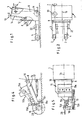
- FIGS. 1 to 6 the illustrated device for producing joints in road surfaces and the like.
- Floor fixings a frame 1, which is by means of a rigid four-wheel chassis on the floor or a road surface or the like.
- the chassis comprises rear wheels 1a arranged on a rear axle and two front wheels 2 which are suspended from the front ends of rigid arms 3 and 4 of the frame 1.
- the wheels of the rear axle 1a are driven in a manner known per se by a feed motor, not shown in detail.
- the boom 3 on the right in the direction of travel of the device is arranged approximately as an extension of the right outer side of the frame 1, while the left arm 4 is arranged from the left outer side of the frame 1 towards the center of the device.
- a handwheel 7 arranged at the top of the device frame 1 on a spindle drive, an adjustment of the rear axle 1a for correcting the direction of the device is possible via a roller chain 6 and a chain wheel 5.
- the device frame 1 In its front area, the device frame 1 has a lower, vertically extending frame part 10 with a bearing block 8 which is pivotally supported on the frame part 10 by means of a pin 9 forming a pivot point.
- the bearing block 8 At the end opposite the bolt 9, in the example shown on the right-hand side of the device in the direction of travel, in this arrangement the bearing block 8 can be pivoted downward from an arch at an acute angle from a horizontal position running parallel to the axes of rotation of the undercarriage wheels .
- the bearing block 8 is provided with an adjusting head 12 which is designed as a nut and extends through an elongated hole 11 in the frame part 10 and which has a threaded spindle 14 which can be actuated by means of a handwheel 13 for a displacement and adjustment of the bearing block between the horizontal position and one in FIG. 3 is in adjustment engagement at 8 'shown in dash-dot lines.
- a rocker 15 (Fig. 4 to 6) is articulated with its pivot axis 16 to the bearing block 8.
- the rocker 15 carries on the top a drive motor 15a for a circular saw blade or a cutting disc 20 which is arranged on a cutting shaft 18 in the front end region of the rocker 15.
- the drive connection from the motor 15a to the cutting shaft 18 takes place in the example shown by means of a V-belt drive 15b.
- the cutting shaft 18 is short and the cutting disk 20 at the free end of the cutting shaft 18 is arranged approximately in the middle of the device, as is characterized by the vertical longitudinal center plane 1b of the device.
- the front rocker area 19 engages over the front wheel 2 on the left in the direction of travel, so that the cutting shaft 18 with its cutting disk 20 can be completely lowered both in the case of vertical and oblique cuts.
- a guide roller 15c is arranged in the front region of the rocker 15 on its underside and provides the rocker 15 with a bottom-side support in the cutting operation.
- the guide roller 15c thus forms a lower stop for the downward pivoting movement of the rocker 15 under the load on the units arranged thereon, in particular the drive motor 15a, and thus also limits the depth of cut of the cutting disc 20. Since the cutting depth of the cutting disc 20 corresponds to that Working conditions must be adjustable, the guide roller 15c is supported on the rocker 15 for height adjustment.
- the guide roller 15c is fastened with its holder to the free end of the piston rod of the piston of a pressure-operated, e.g. hydraulic, working cylinder 15d, but other actuators, e.g. a manually operated spindle drive.
- the front wheels 2 of the device are arranged near the cutting shaft 18 for reasons of stability.
- an additional undercarriage is provided in its center of gravity, which consists of two wheels 21 and 22, which come from an operation in contact with the ground
- Position for moving the device by means of mechanical or pressure medium-actuated actuators in an inoperative position located above the floor level can be moved and fixed in this position, which is taken up by the wheels 21 and 22 in the cutting operation of the cutting disc 20.
- the rocker 15 is supported on the device frame 1 by means of an actuator 17, in the example shown in the form of a pressure-actuated working cylinder. Since the actuator 17 has to perform a lateral movement when adjusting the tilt of the rocker, it is connected to the underside of the rocker 15 on the one hand and the device frame 1 on the other via spherical suspension members or ball joint bearings.
- the pivot axis 16 of the rocker 15 runs parallel to the cutting shaft 18 in all rocker settings and in particular also in the inclined positions of the rocker 15. This is illustrated in particular in FIG. 6, in which the rocker 15 is shown inclined by the design-related maximum inclination angle of, for example, 30 °. This inclination of the entire rocker 15 is carried out by actuating the handwheel 13. With this arrangement and setting, the downward feed movement and the upward movement of the saw blade 20 are directed parallel to the flanks of the saw blade or the cutting disk 20, as is shown in FIG Double arrow 32 is illustrated. This ensures that the penetration and retraction of the cutting disc 20 take place without the risk of jamming and damage to the cutting disc.
- the guide roller 15c is constantly in the rocker 15 on the front supporting ground engagement with the road surface or the like during the cutting operation of the device. Pavement as particular strength from the F. 4 and 6 can be seen. This constant contact with the ground is particularly necessary if the surface of the road surface is uneven.
- the guide roller 15c drives over such unevenness with corresponding entrainment of the cutting disc 20 held on the rocker 15.
- the actuator 17 is decoupled in the cutting operation of the device in such a way that the rocker 15 corresponds to the Movements of the guide roller 15c can perform free pivoting movements relative to the frame 1.
- the guide roller 15c For a normal rolling movement of the guide roller 15c on the surface of the road surface, the guide roller 15c is mounted in a bearing fork which is fastened to the piston rod of the working cylinder 15d and is freely rotatable about an axis 15e. runs parallel to the axes of rotation of the undercarriage wheels of the device, which are designated by 2a in FIGS. 3 and 6 for the front wheels 2.
- the working cylinder 15d is adjustably supported on the rocker 15 in such a way that regardless of the inclined position set for the rocker 15 or the cutting disc 20, the horizontal or parallel position of the axis of rotation 15e of the guide roller 15c to the axes of rotation of the chassis can be set.
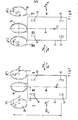
- FIGS. 7 to 10 While cutting vertical joints into a carriageway blanket or the like Fixing the cutting disc to the ground at an angle of 90 ° to the surface of the road surface is illustrated in FIGS. 7 to 10 angular positions or inclinations of the cutting disc 20 which deviate from the .90 ° angle and which are also indicated by a corresponding inclination of the rocker 15 their pivot axis 16 have been brought about in the manner described above. All of the embodiments shown in FIGS. 7 to 10 have in common that the downward feed movement and the upward movement of the cutting disc 20 take place parallel to the cutting disc flanks, so that lateral contact of the cutting disc 20 with the road surface to be cut is avoided.
- Figures 9 and 10 show the device looking towards the front of the device carrying the rocker 15, i.e. against the normal feed and cutting movement. Assuming the view of the operator standing behind the device and looking in the cutting direction, the arrangements shown in FIG. 9 can be referred to as the right-angled positions and the arrangements according to FIG. 10 as the left-angled positions of the saw blade 20 are, these inclinations have been brought about by corresponding inclinations of the pivot axis 16. of the rocker 15.
- FIG. 7 shows a top view of the left-angled cutting disk arrangements according to FIG. 10, while FIG. 8 illustrates the right-angle cutting disk arrangements according to FIG. 9 in a top view.
- the device frame is designated by 61 and 71.
- the rear wheels here designated 62 or 72 and not in driven in more detail, the device receives its normal forward feed movement.
- the front wheels are labeled 63 and 73, respectively.
- 7 and 8 are schematic representations, the cutting shafts. Drive shafts of the cutting discs and their storage not shown.
- the rotation of the cutting disc 20 produces a tangential reaction force F on the circumference of the cutting disc.
- This force acts on the device and can be divided into a vertical component which is irrelevant in the above context and therefore not shown, as well as a horizontally forward component and a horizontal transverse component F. The latter component is of particular importance for the driving behavior and the directional stability of the device.
- the horizontally forward movement component is canceled by a larger rearward force, which is caused by the cutting engagement of the cutting disc 20.
- the rest of this force after subtracting the forward horizontal component is the backward force F v1 .
- the continuous advancement of the device 61 or 71 requires it to be driven and moved forward with a uniform, forward-directed force F.
- the rotary movement of the cutting disc 20 is indicated in FIGS. 7 and 8 by an arrow 65 and 75, respectively.
- embodiments I and V which show simple arrangements of a drive or cutting shaft 92 with a cutting disc 20 by means of ball bearings 94, in which the cutting disc 20 has a left inclination on the left device side (I) and a right inclination on the right device side (V). is arranged with a corresponding Neigunq the cutting shaft 92 to the left or to the right, the forces specified lead to a total torque, which causes a deviation of the device from its straight travel, so that an undesired arcuate Fu g en steel generated and the cutting disc receives pressure from the side resulting in possible damage.
- This total moment consists of the moment M, which is generated by the backward force F v1 and acts on the lever a, and of the moment M, which is generated by the horizontal force component F q and acts on the lever b.
- the sum of both moments rotates the device 61 to the left in the cutting mode of embodiment I and to the right in the same way in the cutting mode of embodiment V.
- a more favorable force ratio results when the cutting disc 20 is arranged with a left inclination on the right side of the device (version II) or instead when the cutting disc 20 is arranged with a right inclination on the left side of the device (version IV).
- the moments M q and M v are opposite to each other and the resulting moment results from a subtraction of the moments.
- both moments are equal, so that the resulting force is O. With easy handling and guidance of the device in the cutting operation, this leads to a straight forward joint cut without any deviations from the straight line.
- a short bearing 102 for the cutting shaft 105 is required, which executes up and down movements in the direction of the double arrow 101.
- the shaft of the V-belt pulley 104 is supported .
- the cutting shaft 105 and the V-belt pulley shaft are in turn connected to one another by two shafts 108 and 111 with bending and ball joints 107 and 109.
- Embodiment IV which, as shown in FIG. 9, has a short bearing arrangement 95 with a cutting shaft 97 and one V-belt pulley 96 used.
- Embodiment IV therefore represents a preferred solution, in which at most the short bearing spacing can lead to high radial loads on the bearings.
- Embodiment III is less preferable in practice, since the V-belt pulley 104 or the like at point 110 even at small depths of cut with the surface of the road surface.
- Floor fixture comes into contact.
- Embodiment VI allows the cutting disc 20 to penetrate into the ground until its clamping flanges 98 almost touch the ground surface.
- a relatively long bearing arrangement 99 can be used to advantage.
- the embodiment VI practically corresponds to the appendix of FIGS. 1 to 6 in the practical embodiment explained in detail and, taking into account the achievable torque compensation and the constructive possibilities, the present. most preferred embodiment.
- the device can also work in reverse with a trailing cutting disc.
Abstract
Description
Die Erfindung betrifft eine Vorrichtung zum Herstellen von Fugen in Straßendecken u.dgl. Bodenbefestigungen nach dem Oberbegriff des Patentanspruchs 1.The invention relates to a device for producing joints in road surfaces and the like. Bodenbefesti g Ungen according to the preamble of
Vorrichtungen dieser Art werden für Schneidarbeiten in Frisch- und Altbeton sowie in Asphalt zum Einschneiden von Quer- und Längsfugen insbesondere im Straßen-, Autobahn- und Flugplatzbau eingesetzt. Ein weiteres Einsatzgebiet dieser Vorrichtungen sind Auf- und Abbrucharbeiten in Beton oder Stahlbeton sowie Reparaturarbeiten in Straßen- u.dgl. Fahrbahndecken. Bei solchen Ausbesserungsarbeiten hat es sich als wünschenswerterwiesen,.die Randseiten eines auszubessernden Teilstücks einer Fahrbahndeckenschräg nach innen abfallen zu lassen, um auf diese Weise günstige.Auflage- und Verankerungsmöglichkeiten für das neu in die Fahrbahndecke einzubringende Teilstück mit dem bestehenden Umgebungsteil der Fahrbahndecke zu schaffen. Mit den bekannten Vorrichtungen der angegebenen Art ist jedoch eine derartige Arbeitsweise nicht möglich, weil die Schneidebene der Schneidscheibe vertikal ausgerichtet ist und somit nur vertikale Fugen in die Straßen- od.dgl. Fahrbahndecke eingeschnitten werden können. Um dabei die Verankerungsmöglichkeiten des neu in die Fahrbahndecke einzubringenden Teilstücks zu verbessern, werden die Seitenränder der das neue-Teilstück aufnehmenden öffnung häufig mit einer Abstufung nach innen ausgeführt. Dies stellt jedoch einen schwierigen, zeitaufwendigen Arbeitsvorgang dar, der einen insgesamt stark verzögernden Einfluß auf solche Ausbesserungsarbeiten nimmt.Devices of this type are used for cutting work in fresh and old concrete as well as in asphalt for cutting transverse and longitudinal joints, especially in road, highway and airfield construction. Another area of application for these devices is demolition and demolition work in concrete or reinforced concrete, and repair work in road and the like. Road surfaces. In the case of such repair work, it has proven to be desirable to drop the edge sides of a section of a road surface to be repaired sloping inwards, in order in this way to create inexpensive support and anchoring options for the part to be newly introduced into the road surface with the existing surrounding part of the road surface. However, such a method of operation is not possible with the known devices of the specified type because the cutting plane of the cutting disc is oriented vertically and thus only vertical joints in the street or the like. Road surface can be cut. In order to improve the anchoring possibilities of the newly introduced into the pavement section, the side edges of the new ones - section receiving opening frequently performed with a step inside. However, this is a difficult, time-consuming operation which has an overall strongly retarding influence on such repair work.
Der Erfindung liegt die Aufgabe zugrunde, eine Vorrichtung zum Herstellen von Fugen in Straßendecken u.dgl. Bodenbefestigungen der eingangs angebenen Art zu'.schaffen, mit deren Hilfe die Herstellung schräger bzw. quer zur Fahrtrichtung der Vorrichtung geneigter Fugen bzw. Einschnitte auf maschinellem Wege unter Einhaltung der Arbeitsgeschwindigkeiten der bekannten Vorrichtungen und unter Erhalt einer guten Manövrierfähigkeit der Vorrichtung möglich ist.The invention has for its object a device for producing joints in pavements and the like. To create ground fastenings of the type specified at the beginning, with the aid of which the production of inclined or transverse inclinations to the direction of travel of the device joints or incisions by machine is possible while observing the working speeds of the known devices and maintaining good maneuverability of the device.
Diese Aufgabe wird nach Erfindung durch eine Ausgestaltung der Vorrichtung gemäß dem Patentanspruch 1 gelöst. Durch die Einstellung der gestellseitigen Schwenkachse der Schneidscheibe in einem spitzen Winkel gegenüber der Drehachse der Gestellräder ist aufgrund der in einer rechtwinklig zu der Schwenkachse stehenden Ebene schneidenden Schneidscheibe gewährleistet, daß.die Schneidscheibe ohne Verklemmungen und Verkantungen in den Fahrbahnbelag eindringen kann und dabei eine in Querrichtung der Vorrichtung geneigte bzw. schräge Schnittfuge erzeugt. Die erfindungsgemäße Vorrichtung kann insoweit die gleichen Arbeitsgeschwindigkeiten wie Vorrichtungen mit senkrechter Schneidebene ihrer Schneidscheibe erzielen, eine Arbeitsweise, die bei der erfindungsgemäßen Vorrichtung grundsätzlich bei parallel zur Drehachse der Gestellräder angeordneter Schwenkachse der Schneidscheibe ebenfalls möglich ist. Die Anordnung der Schneidscheibe in der Weise, daß die im Schneidbetrieb mit schrägstehender Schneidscheibe auf die Vorrichtung-in einer horizontalen Ebene einwirkenden Drehmomente einanander entgegengerichtet sinn, gewährleistet in diesem Zusammenhang die gute Richtungsstabilitätder Vorrichtung durch weitestgehenden Momentenausgleich der im Schneidbetrieb auftretenden Kräfte, womit der Tendenz eines durch einen Schrägschnitt verursachten unkontrollierten Abweichens oder Abtreibens von der vorgegebenen Fahrt- und Arbeitsrichtung der Vorrichtung entgegengewirkt wird. Auf diese Weise lassen sich mit einem hohen Maß an Genauigkeit Schrägfugen in Fahrbahndecken u.dgl. Bodenbefestigungen einbringen, wodurch Ausbesserungsarbeiten insgesamt zügig vonstatten gehen können und die ausgebesserten Teilstücke der Fahrbahndecke ein hohes Maß an Haltbarkeit durch gute Abstützung und Verankerung mit den umgebenden Randteilen der Fahrbahndecke erhalten.This object is achieved according to the invention by an embodiment of the device according to
Zahlreiche weitere Merkmale und Vorteile der Erfindung ergeben sich aus den Unteransprüchen und der nachstehenden Beschreibung in Verbindung mit der Zeichnung, in der mehrere Ausführungsbeispiele des Gegenstands der Erfindung schematisch veranschaulicht sind. In der Zeichnung zeigen:
- Fig. 1 eine Seitenansicht des Vorrichtungsgestells zur Aufnahme einer Wippe mit Schneidscheibe,
- Fig. 2 eine Draufsicht auf das Vorrichtungsgestell nach Fig. 1,
- Fig. 3 eine Stirnansicht einer Einzelheit der Lagerung der Wippe am Vorrichtungsgestell,
- Fig. 4 eine Seitenansicht der Wippe im am Vorrichtungsgestell nach den Fig. 1 und 2 befestigten Zustand,
- Fig. 5 eine Draufsicht auf die Wippe.nach Fig. 4,
- Fig. 6 eine Stirnansicht der Wippe in Verbindung mit dem Vorrichtungsgestell,
- Fig. 7' und 8 je eine schematische Draufsicht zur Veran- schaulichung verschiedener Anordnungen der Schneidscheibe am Vorrichtungsgestell und
- Fig. 9 und 10 Stirnansichten zu den Draufsichten nach den Fig. 7 und 8 jeweils mit Blickrichtung auf die Schneidscheibe.
- 1 is a side view of the device frame for receiving a rocker with a cutting disc,
- 2 is a plan view of the device frame of FIG. 1,
- 3 is an end view of a detail of the mounting of the rocker on the device frame,
- 4 is a side view of the rocker in the state attached to the device frame according to FIGS. 1 and 2,
- 5 is a top view of the rocker according to FIG. 4,
- 6 is an end view of the rocker in connection with the device frame,
- 7 'and 8 are each a schematic top view for illustrating various arrangements of the cutting disc on the device frame and
- FIGS. 9 and 10 end views of the top views according to FIGS. 7 and 8 each with a view of the cutting disc.
Wie sich zunächst aus den Fig. 1 bis 6 ergibt, umfaßt die dargestellte Vorrichtung zum Herstellen von Fugen in Straßendecken u.dgl. Bodenbefestigungen ein Gestell 1, das mittels eines starren Vierradfahrwerks auf dem Boden bzw. einer Straßendecke od.dgl. Bodenbefestigung verfahrbar ist. Das Fahrwerk umfaßt auf einer Hinterachse 1a angeordnete Hinterräder und zwei Vorderräder 2, die an den vorderen Enden starrer Ausleger 3 und 4 des Gestells 1 aufgehängt sind. Die Räder der Hinterachse 1a sind in an sich bekannter Weise von einem nicht näher dargestellten Vorschubmotor angetrieben. Der in Fahrtrichtung der Vorrichtung rechte Ausleger 3 ist etwa in Verlängerung der rechten Außenseite des Gestells 1 angeordnet, während der linke Ausleger 4 von der linken Außenseite des Gestells 1 zur Vorrichtungsmitte hin angeordnet ist. Mittels eines oben am Vorrichtungsgestells 1 angeordneten Handrades 7 an einem Spindeltrieb ist über eine Rollenkette 6 und ein.Kettenrad 5 eine Verstellung der Hinterachse 1a zur Richtungskorrektur der Vorrichtung möglich.As can be seen initially from FIGS. 1 to 6, the illustrated device for producing joints in road surfaces and the like. Floor fixings a
In seinem vorderen Bereich besitzt das Vorrichtungsgestell 1 einen unteren, senkrecht verlaufenden Gestellteil 10 mit einem Lagerbock 8, der mittels eines einen Drehpunkt bildenden Bolzens 9 am Gestellteil 10 schwenkbar abgestützt.ist. An dem dem Bolzen 9 gegenüberliegenden Ende, bei dem dargestellten Beispiel auf der in Fahrtrichtung rechten Seite der Vorrichtung, kann bei dieser Anordnung der Lagerbock 8 aus einer parallel zu den Drehachsen der Fahrwerksräder verlaufenden, horizontalen Lage auf dem Bogen eines spitzen Winkels nach unten verschwenkt werden. Hierzu ist der Lagerbock 8 mit einem als Mutter ausgebildeten, ein Langloch 11 im Gestellteil 10 durchgreifenden Verstellkopf 12 versehen, der mit einer mittels eines Handrades-13 betätigbaren Gewindespindel 14 für eine Verlagerung und Einstellung des Lagerbockes zwischen der horizontalen Stellung und einer in Fig. 3 bei 8' strichpunktiert dargestellten Schrägstellung in Verstelleingriff steht.In its front area, the
Eine Wippe 15 (Fig. 4 bis 6) ist mit ihrer Schwenkachse 16 an den Lagerbock 8 angelenkt. Die Wippe 15 trägt oberseitig einen Antriebsmotor 15a für ein kreisförmiges Sägeblatt bzw. eine Schneidscheibe 20, die auf einer Schneidwelle 18 im vorderen Endbereich der Wippe 15 angeordnet ist. Die Antriebsverbindung vom Motor 15a.zur Schneidwelle 18 erfolgt bei dem dargestellten Beispiel mittels eines Keilriementriebs 15b. Die Schneidwelle 18 ist kurz ausgebildet und die Schneidscheibe 20 am freien Ende der Schneidwelle 18 ist etwa in der Vorrichtungsmitte angeordnet, wie sie durch die vertikale Längsmittelebene 1b der Vorrichtung gekennzeichnet ist. Der vordere Wippenbereich 19 greift in der abgesenkten Stellung der Wippe 15 über das in Fahrtrichtung linke Vorderrad 2 hinweg, so daß die Schneidwelle 18 mit ihrer Schneidscheibe 20 sowohl bei Vertikal- als auch bei Schrägschnitt vollständig abgesenkt werden kann.A rocker 15 (Fig. 4 to 6) is articulated with its
Eine Führungsrolle 15c ist im vorderen Bereich der Wippe 15 an deren Unterseite angeordnet und vermittelt der Wippe 15 im Schneidbetrieb eine bodenseitige Abstützung. Die Führungsrolle 15c bildet somit einen unteren Anschlag für die nach unten gerichtete Schwenkbewegung der Wippe 15 unter der Belastung der auf dieser angeordneten Aggregate, insbesondere des Antriebsmotors 15a,.und begrenzt somit auch die Schnittiefe der Schneidscheibe 20. Da die Schnittiefe der Schneidscheibe 20 entsprechend den Arbeitsbedingungen einstellbar sein muß, ist hierzu die Führungsrolle 15c höhenverstellbar an der Wippe 15 abgestützt. Bei dem dargestellten Beispiel ist die Führungsrolle 15c mit ihrer Halterung an dem freien Ende der Kolbenstange des Kolbens eines druckmittelbetätigten, z.B..hydraulischen, Arbeitszylinders 15d befestigt, an dessen Stelle jedoch auch andere Stellglieder, z.B. ein handbetätigter Spindeltrieb, treten können.A
Die Vorderräder 2 der Vorrichtung sind aus Stabilitätsgründen nahe der Schneidwelle 18 angeordnet. Zum leichteren Manövrieren der Vorrichtung ist ein in deren Schwerpunkt angeordnetes Zusatzfahrwerk vorgesehen, das aus zwei Rädern 21 und 22 besteht, die aus einer in Bod-enberührung stehenden Betriebsstellung zum Verfahren der Vorrichtung mittels mechanischer oder druckmittelbetätigter Stellglieder in eine oberhalb der Bodenebene befindliche Außerbetriebsstellung beweg- und in dieser festsetzbar sind, die von.den Rädern 21 und 22 im Schneidbetrieb der Schneidscheibe 20 eingenommen wird.The
Für ein-Absenken und insbesondere Ausheben der Schneidscheibe 20 aus der geschnittenen Fuge ist die Wippe 15 mittels eines Stellgliedes 17-, bei dem-dargestellten Beispiel in Form eines druckmittelbetätigten Arbeitszylinders, am Vorrichtungsgestell 1 abgestützt. Da das Stellglied 17 beim Verstellen der Wippenneigung eine seitliche Bewegung auszuführen hat, ist es über sphärische Aufhängungsorgane bzw. Kugelgelenklager mit der Unterseite der Wippe 15 einerseits und dem Vorrichtungsgestell 1 andererseits verbunden.For lowering and in particular lifting the
Die Schwenkachse 16 der Wippe 15 verläuft in allen Wippeneinstellungen und insbesondere auch in den Schrägstellungen der Wippe 15 parallel zur Schneidwelle 18. Dies veranschaulicht insbesondere Fig. 6, in der die Wippe 15 um den auslegungsbedingt maximalen Neigungswinkel von beispielsweise 30° geneigt dargestellt ist. Diese Schrägstellung der gesamten Wippe 15 erfolgt durch Betätigung des Handrades 13. Bei dieser Anordnung und Einstellung sind die abwärtsgerichtete Vorschubbewegung und die Aufwärtsbewegung des Sägeblattes 20 parallel zu den Flanken des Sägeblattes bzw. der Schneidscheibe 20 gerichtet, wie es in Fig. 6.durch den Doppelpfeil 32 veranschaulicht ist. Hierdurch ist gewährleistet, daß das Eindringen und das Zurückziehen der Schneidscheibe 20 ohne die Gefahr eines Festklemmens und einer Beschädigung der Schneidscheibe erfolgen.The
Die Führungsrolle 15c steht während des Schneidbetriebs der Vorrichtung ständig in die Wippe 15 vorderseitig abstützendem Bodeneingriff mit dem Straßenbelag od.dgl. Fahrbahndecke, wie es insbesondere aus den Fig. 4 und 6 ersichtlich ist. Diese ständige Bodenberührung ist insbesondere dann erforderlich, wenn die Straßendecke in ihrer Oberfläche Unebenheiten aufweist. Die Führungsrolle 15c überfährt solche Unebenheiten unter entsprechender Mitnahme der an der Wippe 15 gehaltenen Schneidscheibe 20. Damit diese Schwenkbewegung der Wippe 15 gegenüber dem Gestell 1 möglich ist, ist das Stellglied 17 im Schneidbetrieb der Vorrichtung in der Weise entkoppelt, daB die Wippe 15 entsprechend den Bewegungen der Führungsrolle 15c freie Schwenkbewegungen gegenüber dem Gestell 1 ausführen kann. Auchdiese Schwenkbewegungen erfolgen für die Schneidscheibe 20 in einer Ebene entsprechend dem Doppelpfeil 32 und nehmen daher keinen nachteiligen Einfluß auf die Schneidscheibe 20. Eine Schnittiefeneinstellung mittels des Stellgliedes 17 oder eines mechanischen Anschlags zwischen der Wippe 15 und dem Gestell 1 würde demgegenüber vertikale Auf-und Abbewegungen auf die Schneidscheibe 20 beim Überqueren von Unebenheiten der Vorrichtung entsprechend dem Doppelpfeil 3-3 hervorrufen, mit der Folge axialer Verlagerungen der Schneidscheibe 20 in bezug auf die Schnittfuge sowie unerwünschter Reibungsberührung zwischen Schneidscheibe und Schnittfläche sowie Leistungsverlusten, verringerter Schnittgeschwindigkeit und Beschädigungen der Schneidscheibe.The
Für eine normale Abrollbewegung der Führungsrolle 15c auf der Oberfläche der Fahrbahndecke ist die Führungsrolle 15c in einer an der Kolbenstange des Arbeitszylinders 15d befestigten Lagergabel.um eine Achse 15e frei drehbar gelagert., die horizontal.bzw. parallel zu den Drehachsen der Fahrwerksräder der Vorrichtung verläuft, die in den Fig. 3 und 6 für die Vorderräder 2 mit 2a bezeichnet sind. Der Arbeitszylinder 15d ist dabei in der Weise einstellbar an der Wippe 15 abgestützt, daß ungeachtet der für die Wippe 15 bzw. die Schneidscheibe 20 eingestellten Schräglage die horizontale bzw. zu den Drehachsen des Fahrwerks parallele Lage der Drehachse 15e der Führungsrolle 15c eingestellt werden kann.For a normal rolling movement of the
Während zum Einschneiden senkrechter Fugen in eine Fahrbahndecke od.dgl. Bodenbefestigung die Schneidscheibe in einem Winkel von 90° zur Oberfläche der Fahrbahndecke angeordnet ist, sind in den Fig. 7 bis 10 von dem .90°-Winkel abweichende Winkelstellungen bzw. Neigungen der Schneidscheibe 20 veranschaulicht, die durch eine entsprechende Neigung der Wippe 15 mit ihrer Schwenkachse 16 in der oben beschriebenen Weise herbeigeführt worden sind. Allen in den Fig. 7 bis 10 gezeigten Ausführungsformen ist gemeinsam, daß die abwärts gerichtete Vorschubbewegung und die Aufwärtsbewegung der Schneidscheibe 20 parallel zu den Schneidscheibenflanken erfolgen, so daß seitliche Berührungen der Schneidscheibe 20 mit der zu schneidenden Fahrbahndecke vermieden sind. Dies ist dadurch bedingt, daß die Schneidwelle 18, die der Schneidscheibe 20 eine Umlaufbewegung in einer senkrecht zu ihrer Längserstreckung verlaufenden Ebene vermittelt, stets parallel zur Schwenkachse 16 der Wippe 15 ausgerichtet ist. Diese Auf- und Abbewegungen sind in den Fig. 9 und 10 durch Richtungspfeile 91 und 101 kenntlich gemacht.While cutting vertical joints into a carriageway blanket or the like Fixing the cutting disc to the ground at an angle of 90 ° to the surface of the road surface is illustrated in FIGS. 7 to 10 angular positions or inclinations of the
Die Fig. 9 und 10 zeigen die Vorrichtung mit Blickrichtung auf die die Wippe 15 tragende Vorderseite der Vorrichtung, d.h. entgegen der normalen Vorschub- und Schneidbewegung. Geht man .von derBlickrichtung des Bedienungsmannes aus, der hinter der Vorrichtung steht und in Schneidrichtung blickt, so können die in Fig. 9 gezeigten Anordnungen als nach rechts geneigte und die Anordnungen nach Fig.. 10 als nach links geneigte Stellungen .des Sägeblattes 20 bezeichnet werden, wobei diese Neigungen durch entsprechende Neigungen der Schwenkachse 16.der Wippe 15 herbeigeführt worden sind.Figures 9 and 10 show the device looking towards the front of the device carrying the
Die Fig. 7 veranschaulicht in Draufsicht die nach links geneigten Schneidscheibenanordnungen gemäß Fig. 10, während Fig. 8 die Schneidscheibenanordnungen mit Rechtsneigung gemäß Fig. 9 in Draufsicht veranschaulicht. In den Fig. 7 und 8 ist mit 61 und 71 das Vorrichtungsgestell bezeichnet. Mittels der Hinterräder, die hier mit 62 bzw. 72 bezeichnet und in nicht näher dargestellter Weise angetrieben sind, erhält die Vorrichtung ihre normale Vorschubbewegung in Vorwärtsrichtung. Die Vorderräder.sind mit 63 bzw. 73 bezeichnet. Da-es sich bei den Fig. 7 und 8 um Prinzipdarstellungen handelt, sind die Schneidwellen.bzw. Antriebswellen der Schneidscheiben und deren Lagerung nicht dargestellt.FIG. 7 shows a top view of the left-angled cutting disk arrangements according to FIG. 10, while FIG. 8 illustrates the right-angle cutting disk arrangements according to FIG. 9 in a top view. 7 and 8, the device frame is designated by 61 and 71. By means of the rear wheels, here designated 62 or 72 and not in driven in more detail, the device receives its normal forward feed movement. The front wheels are labeled 63 and 73, respectively. 7 and 8 are schematic representations, the cutting shafts. Drive shafts of the cutting discs and their storage not shown.
Die Drehung der Schneidscheibe 20 erzeügt eine tangentiale Reaktionskraft F am Schneidscheibenumfang. Diese Kraft wirkt auf die Vorrichtung ein und kann in eine im vorstehenden Sachzusammenhang unbeachtliche und daher nicht gezeigte vertikale Komponente sowie in eine horizontal nach vorn gerichtete Komponente und eine horizontale quergerichtete Komponente F aufgeteilt werden. Die letztgenannte Komponente hat für das Fahrverhalten und die .Richtungsstabilitätder Vorrichtung besondere Bedeutung. Die horizontal nach vorn gerichtete Bewegungskomponente wird durch eine größere nach rückwärts gerichtete Kraft aufgehoben, die durch den Schneideingriff der Schneidscheibe 20 bedingt ist. Der verbleibende Rest dieser Kraft nach Abzug der nach vorn gerichteten horizontalen.Komponente ist die rückwärts gerichtete Kraft Fv1. Der kontinuierliche Vorschub der Vorrichtung 61 bzw. 71 erfordert deren Antrieb und Vorbewegung mit einer gleichmäßigen, vorwärts gerichteten Kraft F . Die Drehbewegung der Schneidscheibe 20 ist in den Fig. 7 und 8 durch einen Richtungspfeil 65 bzw. 75 gekennzeichnet.The rotation of the
Bei den Ausführungsformen I und V, die einfache Anordnungen einer.Antriebs- bzw. Schneidwelle 92 mit Schneidscheibe 20 mittels Kugellagern 94 zeigen, bei denen die Schneidscheibe 20 mit Linksneigung an der linkenVorrichtungsseite (I) bzw. mit Rechtsneigung an der rechten Vorrichtungsseite (V) mit entsprechender Neigunq der Schneidwelle 92 nach links bzw. nach rechts angeordnet ist, führen die angegebenen Kräfte zu einem Summenmoment, das eine Abweichung der Vorrichtung aus ihrer Geradeausfahrt bewirkt, so daß ein unerwünschter, bogenförmiger Fugenschnitt erzeugt wird und die Schneidscheibe eine seitliche Druckbeaufschlagung mit der Folge möglicher Beschädigungen erhält. Dieses Summenmoment besteht aus dem Moment M , das durch die rückwärtsgerichtete Kraft Fv1 erzeugt wird und am Hebel a wirkt, sowie aus dem Moment M , das durch die horizontale Kraftkomponente Fq erzeugt wird und am Hebel b wirkt. Die Summe beider Momente dreht die Vorrichtung 61 im Schneidbetrieb der Ausführungsform I nach links und im Schneidbetrieb der Ausführungsform V in der gleichen Weise nach rechts.In embodiments I and V, which show simple arrangements of a drive or cutting
Ein günstigeres Kräfteverhältnis ergibt sich bei einer Anordnung der Schneidscheibe 20 mit Linksneigung auf der rechten Vorrichtungsseite (Ausführung II) oder statt dessen bei Anordnung der Schneidscheibe 20 mit Rechtsneigung auf der linken Vorrichtungsseite (Ausführung IV). In beiden Fällen sind die Momente Mq und Mv einander entgegengerichtet und das resultierende Moment ergibt sich durch eine Subtraktion.der Momente. Unter idealen Bedingungen sind beide Momente gleich groß, so daß die resultierende Kraft O ist. Dies führt bei leichter Handhabung und Führung der Vorrichtung im Schneidbetrieb zu einem geradeaus verlaufenden, vorwärtsgerichteten Fugenschnitt ohne jede Abweichungen von der Geraden.A more favorable force ratio results when the
Die Ausführungsformen II und IV nach den Fig. 7 und 8 bedingen allerdings einen gewissen konstruktiven Aufwand. So ist für die Ausführungsform II, wie in Fig. 10 dargestellt, ein kurzes Lager 102 für die Schneidwelle 105 erforderlich, die in Richtung des Doppelpfeils 101 Auf- und Abbewegungen ausführt.- Mit Hilfe einer zweiten Lageranordnung 103 ist die Welle der Keilriemenscheibe 104 gelagert. Die Schneidwelle 105 und die Keilriemenscheibenwelle sind ihrerseits durch zwei Wellen 108 und 111 mit Biege- und Kugelgelenken 107 und 109 miteinander verbunden.The embodiments II and IV according to FIGS. 7 and 8, however, require a certain amount of construction. 10, a
Dieser vergleichsweise hohe konstruktive Aufwand ist bei der Ausführungsform IV vermieden, die gemäß der Darstellung in Fig. 9 eine kurze Lageranordnung 95 mit einer Schneidwelle 97 und einer Keilriemenscheibe 96 verwendet. Die Ausführungsform IV stellt daher eine bevorzugte Lösung dar, bei der allenfalls der kurze Lagerabstand zu hohen radialen Belastungen der Lager führen kann.This comparatively high design effort is avoided in embodiment IV, which, as shown in FIG. 9, has a
Ein Kompromiß zwischen den beschriebenen extremen Anordnungen der Schneidscheibe 20 ist deren Anordnung im mittleren Bereich der Vorrichtung, d.h. etwa in deren vertikaler Längsmittelebene 1b, wie es für die Ausführungsformen III und VI gezeigt ist. Die Ausführungsform III ist hierbei in der Praxis weniger zu bevorzugen, da die Keilriemenscheibe 104 am Punkt 110 schon bei geringen Schnittiefen mit der Oberfläche der Straßendecke od.dgl. Bodenbefestigung in Berührung gelangt. Die Ausführungsform VI ermöglicht hingegen ein Eindringen der Schneidscheibe 20 in den Boden, bis ihre Klemmflansche 98 fast die Bodenoberfläche berühren. Außerdem kann bei dieser Ausführungsform kräftegünstig eine verhältnismäßig lange Lageranordnung 99 Verwendung finden. Die Ausführungsform VI entspricht praktisch dem anhang der Fig. 1 bis 6 im einzelnen erläuterten praktischen Ausführungsbeispiel und stellt unter Berücksichtigung des erzielbaren Momentenausgleichs und der konstruktiven Möglichkeiten die z.Zt. am meisten bevorzugte Ausführungsform dar.A compromise between the described extreme arrangements of the
Hinsichtlich der Anbringung der Schneidwelle an der Vorrichtung in der Weise, daß die Auf- und Abwärtsbewegungen entsprechend den Doppelpfeilen 91 und 101 parallel'zu den Flanken der Schneidscheibe 20 ausgeführt werden können, besteht anstelle der eingangs erläuterten Ausgestaltung die Möglichkeit, eine lineare Vorschub- bzw. Hubvorrichtung mit einer geraden Führung vorzusehen, die von einem druckmittelbetätigten Arbeitszylinder oder einer Gewindespindel betätigt wird. Eine solche Anordnung ist jedoch in Verbindung mit dem vorzugsweise vorgesehenen Keilriemenantrieb der Schneidwelle weniger geeignet.With regard to the attachment of the cutting shaft to the device in such a way that the upward and downward movements can be carried out in accordance with the
Die Vorrichtung kann auch in Rückwärtsfahrt mit nachlaufender Schneidscheibe arbeiten.The device can also work in reverse with a trailing cutting disc.
Hinsichtlich der anhand der Fig. 7 und 8 erläuterten Möglichkeiten, die Richtungsstabilität bzw. den Geradeauslauf der Maschine dadurch zu verbessern, daß eine Addition der im Schneidbetrieb auf die Vorrichtung in einer horizontalen Ebene einwirkenden Drehmomente M und M vermieden bzw. durch eine Kombination der Neigungsrichtung der Schneidscheibe und deren Anordnung in einem bestimmten Breitenbereich der Vorrichtung eine Kompensation der genannten Drehmomente erreicht wird, bleibt nachzutragen, daß dabei von der für das Schneiden mit Schneidscheiben wie Diamant-Kreissägeblättern allgemein üblichen Drehrichtung ausgegangen worden ist, die in den Fig. 7 und 8 durch einen Pfeil 65 bzw. 75 kenntlich gemacht ist. Es versteht sich in diesem Zusammenhang, daß eine Umkehrung der Drehrichtung der Schneidscheibe 20 auch eine Umkehrung des Richtungssinns der Kräfte Fu bzw. F , zur Folge hat. Dies würde bedeuten, daß bei einer solchen Drehrichtungsumkehr- im Falle der Darstellung gem. Fig. 7 die Lösung I die günstigste und im Falle der Darstellung gem. Fig. 8 die Lösung V jeweils die günstigste wäre, da dann für diese beiden Lösungen die Subtraktion der Momente Mq und Mv eintreten würde.With regard to the possibilities explained with reference to FIGS. 7 and 8, to improve the directional stability or the straight running of the machine by avoiding an addition of the torques M and M acting on the device in a horizontal plane in cutting operation or by a combination of the direction of inclination the cutting disc and its arrangement within a certain width range of the device a compensation of the mentioned torques is to be added that it has been assumed that the direction of rotation which is generally customary for cutting with cutting discs such as diamond circular saw blades has been assumed, which is shown in FIGS. 7 and 8 is indicated by an
Claims (10)
Applications Claiming Priority (2)
| Application Number | Priority Date | Filing Date | Title |
|---|---|---|---|
| DE3200862A DE3200862A1 (en) | 1982-01-14 | 1982-01-14 | DEVICE FOR PRODUCING JOINTS IN ROAD CEILINGS AND THE LIKE FLOOR FASTENINGS |
| DE3200862 | 1982-01-14 |
Publications (1)
| Publication Number | Publication Date |
|---|---|
| EP0085304A1 true EP0085304A1 (en) | 1983-08-10 |
Family
ID=6153009
Family Applications (1)
| Application Number | Title | Priority Date | Filing Date |
|---|---|---|---|
| EP83100153A Withdrawn EP0085304A1 (en) | 1982-01-14 | 1983-01-11 | Joint forming device for roadsurfaces and similar ground coverings |
Country Status (4)
| Country | Link |
|---|---|
| EP (1) | EP0085304A1 (en) |
| DE (1) | DE3200862A1 (en) |
| DK (1) | DK7383A (en) |
| NO (1) | NO830082L (en) |
Cited By (3)
| Publication number | Priority date | Publication date | Assignee | Title |
|---|---|---|---|---|
| EP0169248A1 (en) * | 1984-06-06 | 1986-01-29 | Alfred Dr. Hackmack | Combined road-milling and groove-cutting attachment for excavators, loaders, earth-moving vehicles, rollers and tractors |
| CN105967117A (en) * | 2016-06-28 | 2016-09-28 | 林超 | Conveniently detached stable supporting equipment for building |
| CN114395964A (en) * | 2022-01-14 | 2022-04-26 | 刘雄军 | Road cutting machine convenient to change cutter |
Families Citing this family (10)
| Publication number | Priority date | Publication date | Assignee | Title |
|---|---|---|---|---|
| US4701069A (en) * | 1986-12-10 | 1987-10-20 | Whitney James R | Rain drainage grooves in a road and apparatus for making them |
| DE3642809A1 (en) * | 1986-12-15 | 1988-06-23 | Reinhard Wirtgen | MACHINE FOR MILLING OR PEELING ROAD Paving |
| DE4408396A1 (en) * | 1994-03-12 | 1995-09-21 | Mafu Gmbh | Self propelled milling cutter with automatic guidance |
| US6499809B1 (en) | 1997-09-30 | 2002-12-31 | Snapper Machinery, Inc. | Apparatus for cutting recesses in pavement |
| US6592289B1 (en) * | 2000-08-29 | 2003-07-15 | Leonard A. Weander | Technique for contraction joints in concrete pavement |
| US7837276B2 (en) | 2006-07-06 | 2010-11-23 | Diamond Surface, Inc. | Close proximity grinder |
| US8821063B2 (en) | 2011-12-01 | 2014-09-02 | Surface Preparation Technologies, Llc | Control system and method for road cutting machine |
| US9574310B2 (en) | 2013-09-20 | 2017-02-21 | Surface Preparation Technologies Llc | Method and apparatus for cutting a sinusoidal groove in a road surface |
| US20170211245A1 (en) | 2016-01-21 | 2017-07-27 | Diamond Surface, Inc. | Reduced volume sonic noise alert pattern grinder & method |
| CN108222478B (en) * | 2016-06-28 | 2020-04-28 | 海门市知舟工业设计有限公司 | Building support auxiliary assembly capable of realizing directional conversion |
Citations (5)
| Publication number | Priority date | Publication date | Assignee | Title |
|---|---|---|---|---|
| US2845851A (en) * | 1952-06-03 | 1958-08-05 | Reliance Steel Prod Co | Machine for making anti-skid concrete road surfaces |
| US3007688A (en) * | 1959-10-12 | 1961-11-07 | Concrete Sawing Equipment Inc | Pavement cutting device having aligned abrasive blades |
| CH372696A (en) * | 1961-11-03 | 1963-10-31 | Sogerep S A | Machine for sawing or grinding concrete and asphalt slabs |
| US3141702A (en) * | 1962-04-30 | 1964-07-21 | Amos B Barton | Mobile saw for pavement and the like |
| FR1481149A (en) * | 1966-04-04 | 1967-05-19 | Machine for sawing concrete slabs, and similar work |
-
1982
- 1982-01-14 DE DE3200862A patent/DE3200862A1/en not_active Withdrawn
-
1983
- 1983-01-10 DK DK7383A patent/DK7383A/en not_active Application Discontinuation
- 1983-01-11 EP EP83100153A patent/EP0085304A1/en not_active Withdrawn
- 1983-01-12 NO NO830082A patent/NO830082L/en unknown
Patent Citations (5)
| Publication number | Priority date | Publication date | Assignee | Title |
|---|---|---|---|---|
| US2845851A (en) * | 1952-06-03 | 1958-08-05 | Reliance Steel Prod Co | Machine for making anti-skid concrete road surfaces |
| US3007688A (en) * | 1959-10-12 | 1961-11-07 | Concrete Sawing Equipment Inc | Pavement cutting device having aligned abrasive blades |
| CH372696A (en) * | 1961-11-03 | 1963-10-31 | Sogerep S A | Machine for sawing or grinding concrete and asphalt slabs |
| US3141702A (en) * | 1962-04-30 | 1964-07-21 | Amos B Barton | Mobile saw for pavement and the like |
| FR1481149A (en) * | 1966-04-04 | 1967-05-19 | Machine for sawing concrete slabs, and similar work |
Cited By (4)
| Publication number | Priority date | Publication date | Assignee | Title |
|---|---|---|---|---|
| EP0169248A1 (en) * | 1984-06-06 | 1986-01-29 | Alfred Dr. Hackmack | Combined road-milling and groove-cutting attachment for excavators, loaders, earth-moving vehicles, rollers and tractors |
| CN105967117A (en) * | 2016-06-28 | 2016-09-28 | 林超 | Conveniently detached stable supporting equipment for building |
| CN105967117B (en) * | 2016-06-28 | 2018-08-10 | 浙江森海建设有限公司 | One kind can the convenient stable support equipment of dismounting type building |
| CN114395964A (en) * | 2022-01-14 | 2022-04-26 | 刘雄军 | Road cutting machine convenient to change cutter |
Also Published As
| Publication number | Publication date |
|---|---|
| DK7383D0 (en) | 1983-01-10 |
| DK7383A (en) | 1983-07-15 |
| NO830082L (en) | 1983-07-15 |
| DE3200862A1 (en) | 1983-07-21 |
Similar Documents
| Publication | Publication Date | Title |
|---|---|---|
| DE2364028A1 (en) | MACHINE FOR MACHINING ROAD SURFACES | |
| EP0085304A1 (en) | Joint forming device for roadsurfaces and similar ground coverings | |
| DE3025312A1 (en) | TRACKING OR PLANING DEVICE FOR SKI COUNTRIES OR SLOPES | |
| EP0310074B1 (en) | Milling device to be affixed to a mobile apparatus | |
| AT403812B (en) | MACHINE FOR PRESSING THRESHOLD ANCHORS | |
| DE2835270A1 (en) | ROAD PLANER WITH A SUSPENSION FOR ITS CUTTER | |
| EP0367951B1 (en) | Miller for removing a road surfacing consisting of asphalt, concrete or the like along any pattern | |
| DE2156282A1 (en) | Machine for removing layers, especially worn road surfaces | |
| EP2295642A2 (en) | Road milling device | |
| DE3802584C1 (en) | Excavator | |
| DE2949082A1 (en) | DEVICE FOR ATTACHING A SCHUER TOOL AT THE FRONT OF A VEHICLE | |
| DE8200660U1 (en) | DEVICE FOR PRODUCING JOINTS IN ROAD CEILINGS AND THE LIKE FLOOR FASTENINGS | |
| EP0060387A2 (en) | Cleaning apparatus, particularly for motorway signs | |
| DE3642809A1 (en) | MACHINE FOR MILLING OR PEELING ROAD Paving | |
| AT395877B (en) | DEVICE FOR ROWING AND LEVELING A TRAFFIC AREA COVERED AND / OR ICE-FROZEN | |
| DE2919154C2 (en) | Device for processing road surfaces | |
| DE2430215A1 (en) | Heavy machine travel frame - comprises bogie removable when machine is resting on ground and working | |
| DE19531952C2 (en) | Joint cutting device for longitudinal and transverse joints | |
| DE2264710C3 (en) | ||
| DE2209829C3 (en) | Mobile road processing machine | |
| DE3032351C2 (en) | Track tamping machine | |
| CH587386A5 (en) | ||
| DE2203530C2 (en) | Machine for milling off road surfaces | |
| DE3615996C2 (en) | Device for leveling and compressing bulk materials | |
| DE1634636C2 (en) | Mobile pile driver, especially for pile driving parallel sheet pile walls |
Legal Events
| Date | Code | Title | Description |
|---|---|---|---|
| PUAI | Public reference made under article 153(3) epc to a published international application that has entered the european phase |
Free format text: ORIGINAL CODE: 0009012 |
|
| AK | Designated contracting states |
Designated state(s): AT CH FR GB IT LI NL SE |
|
| STAA | Information on the status of an ep patent application or granted ep patent |
Free format text: STATUS: THE APPLICATION IS DEEMED TO BE WITHDRAWN |
|
| 18D | Application deemed to be withdrawn |
Effective date: 19840411 |
|
| RIN1 | Information on inventor provided before grant (corrected) |
Inventor name: OSTERTAG, ALFRED |