EP0367951B1 - Miller for removing a road surfacing consisting of asphalt, concrete or the like along any pattern - Google Patents
Miller for removing a road surfacing consisting of asphalt, concrete or the like along any pattern Download PDFInfo
- Publication number
- EP0367951B1 EP0367951B1 EP89117186A EP89117186A EP0367951B1 EP 0367951 B1 EP0367951 B1 EP 0367951B1 EP 89117186 A EP89117186 A EP 89117186A EP 89117186 A EP89117186 A EP 89117186A EP 0367951 B1 EP0367951 B1 EP 0367951B1
- Authority
- EP
- European Patent Office
- Prior art keywords
- milling
- chassis
- miller
- milling head
- shaft
- Prior art date
- Legal status (The legal status is an assumption and is not a legal conclusion. Google has not performed a legal analysis and makes no representation as to the accuracy of the status listed.)
- Expired - Lifetime
Links
Images


Classifications
-
- B—PERFORMING OPERATIONS; TRANSPORTING
- B28—WORKING CEMENT, CLAY, OR STONE
- B28D—WORKING STONE OR STONE-LIKE MATERIALS
- B28D1/00—Working stone or stone-like materials, e.g. brick, concrete or glass, not provided for elsewhere; Machines, devices, tools therefor
- B28D1/18—Working stone or stone-like materials, e.g. brick, concrete or glass, not provided for elsewhere; Machines, devices, tools therefor by milling, e.g. channelling by means of milling tools
-
- E—FIXED CONSTRUCTIONS
- E01—CONSTRUCTION OF ROADS, RAILWAYS, OR BRIDGES
- E01C—CONSTRUCTION OF, OR SURFACES FOR, ROADS, SPORTS GROUNDS, OR THE LIKE; MACHINES OR AUXILIARY TOOLS FOR CONSTRUCTION OR REPAIR
- E01C23/00—Auxiliary devices or arrangements for constructing, repairing, reconditioning, or taking-up road or like surfaces
- E01C23/06—Devices or arrangements for working the finished surface; Devices for repairing or reconditioning the surface of damaged paving; Recycling in place or on the road
- E01C23/08—Devices or arrangements for working the finished surface; Devices for repairing or reconditioning the surface of damaged paving; Recycling in place or on the road for roughening or patterning; for removing the surface down to a predetermined depth high spots or material bonded to the surface, e.g. markings; for maintaining earth roads, clay courts or like surfaces by means of surface working tools, e.g. scarifiers, levelling blades
- E01C23/085—Devices or arrangements for working the finished surface; Devices for repairing or reconditioning the surface of damaged paving; Recycling in place or on the road for roughening or patterning; for removing the surface down to a predetermined depth high spots or material bonded to the surface, e.g. markings; for maintaining earth roads, clay courts or like surfaces by means of surface working tools, e.g. scarifiers, levelling blades using power-driven tools, e.g. vibratory tools
- E01C23/088—Rotary tools, e.g. milling drums
- E01C23/0885—Rotary tools, e.g. milling drums with vertical or steeply inclined rotary axis
Definitions
- the invention relates to a milling machine for removing an asphalt, concrete or the like existing road surface according to the preamble of claim 1.
- a milling machine is known from AT-B 374 523, the chassis of which runs on rails with fixed wheels.
- a guide frame with a carriage which can be moved transversely to the direction of travel is arranged transversely to the direction of travel of the chassis and carries a milling head directed towards the ground with a diamond-coated disk and vertical drive shaft.
- the rails guiding the chassis must be designed so that the roadway area to be removed lies between the rails. Only then is the milling machine placed on the track and the cutting disc lowered into the track groove in order to remove part of the pavement for leveling.
- the entire milling machine When lifting off the old road surface, the entire milling machine has to be moved in the longitudinal direction of the rails, the chassis always being above the working area of the milling head, that is to say largely covering the working area.
- the roadway area to be removed is inevitably limited by the rails to be laid beforehand, which can lead to problems in particular if the area to be removed is considerably larger than the track width of the chassis.
- the rails must then be laid on the pavement to be renovated, which is technically and time-consuming.
- the known milling machine is essentially designed for machining straight sections; Strong curvatures such as in the edge areas at road crossings and the like cannot be machined with reasonable effort.
- the invention has for its object to develop a generic milling machine such that a road surface or the like. Can be milled along any contour without great technical effort and time-consuming setup.
- the chassis is freely steerable, so it does not run on rails.
- the milling head can thus be moved into a starting position that is favorable for machining by maneuvering the chassis.
- the telescopic arm which is adjustable in length and carries the vertically extending milling head carrier plate with the drive motor and the milling shaft, is aligned in the longitudinal direction of the chassis and protrudes beyond the chassis. This enables a visual inspection of the working area of the milling head. Due to the design as a telescopic arm, the milling head is adjustable in the longitudinal direction of the chassis; The carriage can be moved transversely to the longitudinal axis of the chassis by means of the carriage which can be moved transversely to the longitudinal axis of the chassis on the guide frame.
- the milling head By combining the movements in the chassis longitudinal direction and transversely to the chassis longitudinal direction, the milling head can be moved into any position without moving the chassis itself. Circles can be milled as well as any contours without great technical difficulties and scaffolding. It is essential that the milling head, once lowered to its working level, does not change its height despite its movement, since the steerable chassis remains stationary during machining of the contour.
- the chassis of the milling machine according to the invention is advantageously designed with height-adjustable wheels, so that the milling unit can be arranged at a fixed height on the support arm. It may also be expedient to attach the milling unit to the support arm in a height-adjustable manner and to use a chassis with height-fixed wheels.
- the milling machine consists of a chassis 1 which is supported on the floor 3 via wheels 2.
- Each wheel 2 is attached to the piston rod 4, which is preferably square in section, of a piston / cylinder unit 5.
- the piston rod made of square tube is in the direction of the arrow 6 adjustable in height so that the position of the chassis 1 to the floor 3 can be adjusted as desired.
- At least the two wheels 2 located at the front in the direction of travel 7 are arranged so as to be rotatable about vertical steering axes 8, for which purpose a rotating ring 4a is arranged between the piston rod 4 and the wheel 2.
- a wheel 2 is fixed on the turntable 4a in a rotationally fixed manner via a wheel carrier 4b.
- the rotation of the wheel 2 is also controlled hydraulically.
- All four wheels of the chassis are preferably rotatable about vertical steering axes 8. In this way, the chassis is easy to maneuver.
- a drive motor 9 is arranged on the chassis 1 and lies approximately in front of the rear wheels 2 in the direction of travel 7.
- the drive motor 9 is preferably an internal combustion engine which is coupled to a hydraulic motor 10.
- the hydraulic motor 10 feeds - via the control panel 11 - the piston / cylinder units 5 of the individual impellers 2 and the hydraulic wheel hub motors (not shown) arranged on the individual impellers 2.
- the steering movement about the steering axles 8 is hydraulically controlled by means of a steering wheel 12 provided on the control panel 11.
- the control panel 11 is preferably arranged on a support arm 19 described in more detail below, so that the control seat 12a forms the highest point of the milling machine. The driver thus has a clear view of all sides, which is necessary for precise work.
- a guide frame 13 is fastened, which lies transverse to the longitudinal axis 14 of the chassis.
- the cross member 15 of the guide frame are parallel to each other at a right angle to the longitudinal central axis 14 (Fig. 2).
- the cross members 15 have a U-shape Cross-section and face each other with their openings. They are rigidly connected to one another at their ends by longitudinal beams 16 running parallel to the longitudinal central axis 14 and are also fixed, preferably welded, to the frame of the chassis 1.
- a carriage 17 is guided in the U-shaped cross members 15.
- This consists essentially of a rectangular frame lying in the plane of the cross member 15, on the narrow sides of which two sliding rollers 18 are arranged, which are held in the U-profile of the cross member.
- An outer square tube 19 is fastened on the carriage 17 and can thus be moved in the guide frame 13 transversely to the longitudinal central axis 14 of the chassis 1.
- a hydraulic actuating device 20 in particular, is provided, which in the exemplary embodiment consists of a hydraulic piston / cylinder unit.
- the front end of the piston rod 21 is articulated on the carriage 17, while the rear end of the cylinder 22 is fixed on the side member 16.
- an inner square tube 25 is axially displaceably guided.
- an adjusting device 26 is arranged on a long side of the outer square tube 19, which in the exemplary embodiment shown consists of a hydraulic piston / cylinder unit.
- the rear end of the cylinder 27 is articulated on the rear end of the square tube 19 and the front end of the piston rod 28 on the inner square tube 25.
- the inner square tube 25 can be moved in the sense of the double arrow 29 with the hydraulic piston / cylinder unit 26.
- the guide frame 13 projects laterally over the chassis 1, so that the carriage can be moved to the side next to the chassis.
- the length of the outer square tube 19 is also greater than the width of the guide frame 13 measured in the direction of the longitudinal central axis 14.
- the square tube 19 preferably projects further at its front end than at its rear end.
- the mutually movable square tubes 19, 25 together form a support arm 30 which projects in the direction of travel 7 (FIG. 1) beyond the front end of the chassis 1.
- a vertical support plate 31 is attached, the lower end 32 of which faces the floor is located slightly below the height of the chassis 1. The upper end of the support plate 31 projects vertically beyond the outer square tube 19.
- Horizontal holding flanges 33 to 36 extend from the carrier plate in the direction of travel 7 to the front, the uppermost holding flange 36 holding a drive 37, preferably a hydraulic geared motor. From the drive 37 leads through the other holding flanges 33 to 35 a milling shaft 38 which carries a milling head 39 at its lower end.
- the - preferably made of solid material - milling shaft 38 is held and supported in the holding flanges 33 to 35 in specialist bearings.
- a bearing and lubrication device 40 for the milling shaft 38 is provided between the holding flange 34 and the holding flange 35. Furthermore, a pressure bearing acting from above and from below is advantageously provided.
- the milling head 39 is held in a rotationally fixed manner by means of a quick-release fastener at the lower free end of the milling shaft 38 and lies below the lower end 32 of the carrier plate 31 at the level of the wheels 2.
- the hydraulic motor 37 is connected to the control panel 11 via a hydraulic hose 41 and is in the Speed controlled from the control panel. In this way, the milling head is arranged at a fixed height on the support arm 30.
- the pavement can be milled along any contour. If, for example, a square manhole cover 42 or a round manhole cover 43 is provided in the roadway, the milling machine moves into position and the height of the milling head 39 is adjusted by changing the height of the impellers.
- the milling head 39 is moved up to the manhole cover 43 or the manhole cover 42 via the hydraulic adjusting devices 20, 26.
- the milling head 39 is guided along the circular contour of the duct cover 43 by superimposing the adjusting movements of the adjusting device 20, 26. If it is necessary to mill along the contour of a manhole cover 42, one or the other hydraulic actuating device is controlled independently of the other.
- the milling shaft is driven at around 50 revolutions per minute.
- the milling head used in the exemplary embodiment according to FIGS. 1 and 2 is shown enlarged in section in FIG. 3. It essentially consists of a cylindrical body 44 with a central receptacle 45 provided on one end face.
- the cylindrical body is equipped with milling teeth 47 approximately to half the height and on its end face 46 facing the floor 3.
- milling teeth 47 approximately to half the height and on its end face 46 facing the floor 3.
- These are evenly distributed over the circumference of the body 44.
- the milling teeth arranged on the circumferential surface 49 are arranged helically and form a turn which merges into the milling teeth 47 standing on the edge.
- the loosened material is gripped by the winding and transported vertically upwards.
- the milling head 39 is non-rotatably connected to the lower end of the milling shaft 38 by a correspondingly designed quick-release fastener or by means of a securing bolt 51.
- the milling head 39 is held on the milling shaft 38 so that it can be replaced easily.
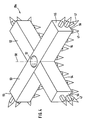
- a beam milling head 39a according to FIG. 4 can also be used.
- This consists of two bars 52, 53 arranged at right angles to one another, the longitudinal sides 54 of which face the floor are evenly covered with milling teeth 47.
- the outer end faces 55 of the beams 52, 53 are equipped with milling teeth 47.
- a milling tooth 47 is arranged, the longitudinal axis of which lies at an angle of approximately 45 ° to the vertical central axis of the milling shaft.
- the milling teeth are preferably arranged in a row from one outer end face 55 over the edge 56 and the long side 54 to the other outer end face 55.
- a receptacle 57 for attaching the milling head 39a to the milling shaft 38 is also provided in the center of the cross bar.
- the guide frame 13, the carriage 17 and the support arm 19 with the support plate 31 and the drive unit are advantageously designed as a structural unit and can be attached to any road construction machine or other vehicle as add-on parts.
Abstract
Description
Die Erfindung bezieht sich auf eine Fräsmaschine zum Abtragen einer aus Asphalt, Beton oder dgl. bestehenden Fahrbahndecke nach dem Oberbegriff des Anspruches 1.The invention relates to a milling machine for removing an asphalt, concrete or the like existing road surface according to the preamble of claim 1.
Zum Abtragen von Fahrbahndecken aus Asphalt, Beton oder dgl. sind große Fräsmaschinen bekannt, die mit rotierenden Fräswalzen arbeiten. Die Arbeitsbreite einer derartigen Straßenbaumaschine ist durch die Breite der Fräswalze bestimmt. Zwar können mit dieser Fräsmaschine in kurzer Zeit große Flächen abgetragen werden; Feinarbeiten wie Abfräsen des Fahrbahnbelages um einen Kanaldeckel oder dgl. sind mit einer derartigen Maschine jedoch nicht möglich. Daher müssen nach Ausführen der großflächigen Fräsarbeiten die verbleibenden Feinarbeiten um im Fahrbahnbelag vorgesehene Einbauten, am rechten und linken Fahrbahnrand, an Straßeneinmündungen und dgl. per Hand ausgeführt werden, was sehr zeitaufwendig ist. Benötigt eine Fräsmaschine zum großflächigen Abtragen des Fahrbahnbelags eines Straßenabschnittes einen Tag, so ist für die noch auszuführenden Feinarbeiten ein weiterer Zeitaufwand von mehreren Tagen anzusetzen.Large milling machines which work with rotating milling drums are known for removing road surfaces from asphalt, concrete or the like. The working width of such a road construction machine is determined by the width of the milling drum. Large areas can be removed in a short time with this milling machine; However, fine work such as milling the road surface around a manhole cover or the like is not possible with such a machine. Therefore, after the large-scale milling work has been carried out, the remaining fine work around the fixtures provided in the road surface, on the right and left edge of the road, at road junctions and the like must be carried out by hand, which is very time-consuming. If a milling machine needs one day to remove the pavement of a section of road over a large area, a further amount of time of several days must be taken for the fine work to be carried out.
Aus der AT-B 374 523 ist eine Fräsmaschine bekannt, deren Fahrgestell mit feststehenden Rädern auf Schienen läuft. Quer zur Fahrtrichtung des Fahrgestells ist ein Führungsrahmen mit einem quer zur Fahrtrichtung verfahrbaren Wagen angeordnet, der einen zum Boden gerichteten Fräskopf mit einer diamantbesetzten Scheibe und vertikaler Antriebswelle trägt. Die das Fahrgestell führenden Schienen müssen so ausgelegt werden, daß der abzutragende Fahrbahnbereich zwischen den Schienen liegt. Erst dann wird die Fräsmaschine auf das Gleis aufgesetzt und die Schneidscheibe in die Spurrinne abgesenkt, um zur Nivellierung einen Teil der Fahrbahndecke abzutragen. Bei dem Abheben des alten Fahrbahnbelags muß die gesamte Fräsmaschine in Längsrichtung der Schienen bewegt werden, wobei das Fahrgestell immer oberhalb des Arbeitsbereichs des Fräskopfes liegt, den Arbeitsbereich also weitgehend verdeckt. Der abzutragende Fahrbahnbereich ist zwangsläufig durch die vorher zu verlegenden Schienen begrenzt, was insbesondere dann zu Problemen führen kann, wenn der abzutragende Bereich erheblich größer ist als die Spurbreite des Fahrgestells. Die Schienen müssen dann auf der zu sanierenden Fahrbahndecke verlegt werden, was technisch und zeitlich sehr aufwendig ist. Die bekannte Fräsmaschine ist im wesentlichen zur Bearbeitung gerader Strecken ausgebildet; starke Krümmungen wie in den Randbereichen an Straßenkreuzungen und dgl. können mit vertretbarem Aufwand nicht bearbeitet werden.A milling machine is known from AT-B 374 523, the chassis of which runs on rails with fixed wheels. A guide frame with a carriage which can be moved transversely to the direction of travel is arranged transversely to the direction of travel of the chassis and carries a milling head directed towards the ground with a diamond-coated disk and vertical drive shaft. The rails guiding the chassis must be designed so that the roadway area to be removed lies between the rails. Only then is the milling machine placed on the track and the cutting disc lowered into the track groove in order to remove part of the pavement for leveling. When lifting off the old road surface, the entire milling machine has to be moved in the longitudinal direction of the rails, the chassis always being above the working area of the milling head, that is to say largely covering the working area. The roadway area to be removed is inevitably limited by the rails to be laid beforehand, which can lead to problems in particular if the area to be removed is considerably larger than the track width of the chassis. The rails must then be laid on the pavement to be renovated, which is technically and time-consuming. The known milling machine is essentially designed for machining straight sections; Strong curvatures such as in the edge areas at road crossings and the like cannot be machined with reasonable effort.
Der Erfindung liegt die Aufgabe zugrunde, eine gattungsgemäße Fräsmaschine derart weiterzubilden, daß ohne großen technischen Aufwand und zeitlich aufwendiges Einrichten eine Fahrbahndecke oder dgl. längs einer beliebigen Kontur abfräsbar ist.The invention has for its object to develop a generic milling machine such that a road surface or the like. Can be milled along any contour without great technical effort and time-consuming setup.
Diese Aufgabe wird erfindungsgemäß nach den kennzeichnenden Merkmalen des Anspruches 1 gelöst.This object is achieved according to the characterizing features of claim 1.
Das Fahrgestell ist frei lenkbar, läuft also nicht auf Schienen. Der Fräskopf kann so durch Rangieren des Fahrgestells in eine für die Bearbeitung günstige Ausgangsposition gefahren werden. Der in seiner Länge einstellbare Teleskoparm, der die sich vertikal erstreckende Fräskopfträgerplatte mit dem Antriebsmotor und der Fräswelle trägt, ist in Fahrgestellängsrichtung ausgerichtet und ragt über das Fahrgestell hinaus. Somit ist eine Sichtkontrolle des Arbeitsbereiches des Fräskopfes möglich. Aufgrund der Ausbildung als Teleskoparm ist der Fräskopf in Längsrichtung des Fahrgestells verstellbar; durch den auf dem Führungsrahmen quer zur Fahrgestellängsachse verfahrbaren Wagen ist eine Bewegung des Tragarms quer zur Fahrgestelllängsachse möglich. Durch Zusammensetzung der Bewegungen in Fahrgestellängsrichtung und quer zur Fahrgestellängsrichtung läßt sich der Fräskopf in jede beliebige Position fahren, ohne das Fahrgestell selbst zu bewegen. Es sind somit ohne große technische Schwierigkeiten und Einrüstarbeiten Kreise ebenso fräsbar wie beliebige Konturen. Dabei ist wesentlich, daß der einmal auf seine Arbeitsebene abgesenkte Fräskopf trotz seiner Bewegung keine Höhenänderung erfährt, da das lenkbare Fahrgestell während der Bearbeitung der Kontur ortsfest verbleibt.The chassis is freely steerable, so it does not run on rails. The milling head can thus be moved into a starting position that is favorable for machining by maneuvering the chassis. The telescopic arm, which is adjustable in length and carries the vertically extending milling head carrier plate with the drive motor and the milling shaft, is aligned in the longitudinal direction of the chassis and protrudes beyond the chassis. This enables a visual inspection of the working area of the milling head. Due to the design as a telescopic arm, the milling head is adjustable in the longitudinal direction of the chassis; The carriage can be moved transversely to the longitudinal axis of the chassis by means of the carriage which can be moved transversely to the longitudinal axis of the chassis on the guide frame. By combining the movements in the chassis longitudinal direction and transversely to the chassis longitudinal direction, the milling head can be moved into any position without moving the chassis itself. Circles can be milled as well as any contours without great technical difficulties and scaffolding. It is essential that the milling head, once lowered to its working level, does not change its height despite its movement, since the steerable chassis remains stationary during machining of the contour.
Vorteilhaft ist das Fahrgestell der erfindungsgemäßen Fräsmaschine mit höhenverstellbaren Rädern ausgeführt, so daß die Fräseinheit höhenfest am Tragarm angeordnet werden kann. Es kann auch zweckmäßig sein, die Fräseinheit höhenverstellbar am Tragarm zu befestigen und ein Fahrgestell mit höhenfesten Rädern einzusetzen.The chassis of the milling machine according to the invention is advantageously designed with height-adjustable wheels, so that the milling unit can be arranged at a fixed height on the support arm. It may also be expedient to attach the milling unit to the support arm in a height-adjustable manner and to use a chassis with height-fixed wheels.
Weiter Merkmale der Erfindung ergeben sich aus den weiteren Ansprüchen, der Beschreibung und der Zeichnung, in der ein schematisch dargestelltes Ausführungsbeispiel der Erfindung gezeigt. Es zeigen:
- Fig. 1
- eine Seitenansicht auf eine erfindungsgemäße Fräsmaschine in schematischer Darstellung,
- Fig. 1a
- einen Schnitt längs der Linie II-II in Fig. 1,
- Fig. 2
- eine Draufsicht auf die Fräseinheit der Fräsmaschine nach Fig. 1,
- Fig. 3
- einen Schnitt durch einen zylindrischen Fräskopf,
- Fig. 4
- eine perspektivische Ansicht eines als Balkenkreuz ausgeführten Fräskopfes.
- Fig. 1
- a side view of a milling machine according to the invention in a schematic representation,
- Fig. 1a
- 2 shows a section along the line II-II in FIG. 1,
- Fig. 2
- 2 shows a plan view of the milling unit of the milling machine according to FIG. 1,
- Fig. 3
- a section through a cylindrical milling head,
- Fig. 4
- a perspective view of a milling head designed as a cross bar.
Die erfindungsgemäße Fräsmaschine besteht aus einem Fahrgestell 1, das über Räder 2 am Boden 3 abgestützt ist. Jedes Rad 2 ist an der im Schnitt vorzugsweise quadratischen Kolbenstange 4 einer Kolben/Zylindereinheit 5 befestigt. Die aus Vierkantrohr gefertigte Kolbenstange ist in Pfeilrichtung 6 höhenverstellbar, so daß die Lage des Fahrgestelles 1 zum Boden 3 beliebig einstellbar ist. Zumindest die beiden in Fahrtrichtung 7 vorne liegenden Räder 2 sind um vertikale Lenkachsen 8 drehbar angeordnet, wozu zwischen Kolbenstange 4 und Rad 2 ein Drehkranz 4a angeordnet ist. An dem Drehkranz 4a ist ein Rad 2 über einen Radträger 4b drehfest festgelegt. Die Drehbewegung des Rades 2 ist ebenfalls hydraulisch gesteuert. Vorzugsweise sind alle vier Räder des Fahrgestelles um vertikale Lenkachsen 8 drehbar. Auf diese Weise ist das Fahrgestell leicht zu manövrieren.The milling machine according to the invention consists of a chassis 1 which is supported on the floor 3 via
Auf dem Fahrgestell 1 ist ein Antriebsmotor 9 angeordnet, der in Fahrtrichtung 7 etwa vor den hinteren Rädern 2 liegt. Der Antriebsmotor 9 ist vorzugsweise ein Verbrennungsmotor, der mit einem Hydraulikmotor 10 gekoppelt ist. Der Hydraulikmotor 10 speist - über das Steuerpult 11 - die Kolben/Zylindereinheiten 5 der einzelnen Laufräder 2 sowie die an den einzelnen Laufrädern 2 angeordneten hydraulischen Radnabenmotoren (nicht dargestellt). Die Lenkbewegung um die Lenkachsen 8 ist mittels eines am Steuerpult 11 vorgesehenen Lenkrades 12 hydraulisch gesteuert. Das Steuerpult 11 ist vorzugsweise auf einem nachfolgend näher beschriebenen Tragarm 19 angeordnet, so daß der Steuersitz 12a den höchsten Punkt der Fräsmaschine bildet. Der Fahrer hat so einen für genaues Arbeiten erforderlichen freien Blick nach allen Seiten.A
Am in Fahrtrichtung 7 vorderen Ende des Fahrgestelles 1 ist ein Führungsrahmen 13 befestigt, der quer zur Fahrgestelllängsachse 14 liegt. Die Querträger 15 des Führungsrahmens liegen dabei parallel zueinander in einem rechten Winkel zur Längsmittelachse 14 (Fig. 2). Die Querträger 15 haben U-förmigen Querschnitt und liegen mit ihren Öffnungen einander zugewandt. Sie sind an ihren Enden durch parallel zur Längsmittelachse 14 verlaufende Längsträger 16 starr miteinander verbunden und ferner auf dem Rahmen des Fahrgestelles 1 festgelegt, vorzugsweise festgeschweißt. Wie aus dem in Fig. 1 längs der Linie I-I in Fig. 2 teilgeschnitten dargestellten Rahmen 13 ersichtlich, ist in den U-förmigen Querträgern 15 ein Wagen 17 geführt. Dieser besteht im wesentlichen aus einem in der Ebene der Querträger 15 liegenden rechteckigen Rahmen, auf dessen Schmalseiten jeweils zwei Gleitrollen 18 angeordnet sind, die in dem U-Profil der Querträger gehalten sind. Auf dem Wagen 17 ist ein äußeres Vierkantrohr 19 befestigt und somit mit diesem quer zur Längsmittelachse 14 des Fahrgestelles 1 im Führungsrahmen 13 verfahrbar. Hierzu ist eine insbesondere hydraulische Stellvorrichtung 20 vorgesehen, die im Ausführungsbeispiel aus einer hydraulischen Kolben/Zylindereinheit besteht. Das vordere Ende der Kolbenstange 21 ist am Wagen 17 angelenkt, während das hintere Ende des Zylinders 22 am Längsträger 16 festgelegt ist.At the front end of the chassis 1 in the direction of travel 7, a
Im äußeren Vierkantrohr 19, dessen Mittelachse 24 parallel zur Längsmittelachse 14 liegt, ist ein inneres Vierkantrohr 25 axial verschieblich geführt. Zum axialen Ausfahren des inneren Vierkantrohrs 25 ist an einer Längsseite des äußeren Vierkantrohres 19 eine Stellvorrichtung 26 angeordnet, die im gezeigten Ausführungsbeispiel aus einer hydraulischen Kolben/Zylindereinheit besteht. Das hintere Ende des Zylinders 27 ist am hinteren Ende des Vierkantrohres 19 und das vordere Ende der Kolbenstange 28 am inneren Vierkantrohr 25 angelenkt. Mit der hydraulischen Kolben/Zylindereinheit 26 ist das innere Vierkantrohr 25 im Sinne des Doppelpfeiles 29 verfahrbar.In the outer
Wie aus der Draufsicht in Fig. 2 ersichtlich, steht der Führungsrahmen 13 seitlich über das Fahrgestell 1 über, so daß der Wagen bis seitlich neben das Fahrgestell verfahrbar ist. Die Länge des äußeren Vierkantrohres 19 ist ferner größer als die in Richtung der Längsmittelachse 14 gemessene Breite des Führungsrahmens 13. Vorzugsweise steht das Vierkantrohr 19 an seinem vorderen Ende weiter über als an seinem hinteren Ende.As can be seen from the top view in FIG. 2, the
Die zueinander verfahrbaren Vierkantrohre 19, 25 bilden zusammen einen Tragarm 30, der in Fahrtrichtung 7 (Fig. 1) über das vordere Ende des Fahrgestelles 1 hinausragt. Am vorderen Ende des inneren Vierkantrohres ist eine vertikale Trägerplatte 31 befestigt, deren dem Boden zugewandtes unteres Ende 32 etwas unterhalb der Höhe des Fahrgestelles 1 liegt. Das obere Ende der Trägerplatte 31 steht über das äußere Vierkantrohr 19 vertikal über.The mutually movable
Von der Trägerplatte erstrecken sich in Fahrtrichtung 7 nach vorne horizontale Halteflansche 33 bis 36, deren oberster Halteflansch 36 einen Antrieb 37, vorzugsweise einen hydraulischen Getriebemotor hält. Vom Antrieb 37 führt durch die anderen Halteflansche 33 bis 35 eine Fräswelle 38, die an ihrem unteren Ende einen Fräskopf 39 trägt. Die - vorzugsweise aus Vollmaterial gefertigte - Fräswelle 38 ist in den Halteflanschen 33 bis 35 in Fachlagern gehalten und abgestützt. Zwischen dem Halteflansch 34 und dem Halteflansch 35 ist eine Lager- und Schmiervorrichtung 40 für die Fräswelle 38 vorgesehen. Ferner ist vorteilhaft je ein von oben und von unten wirkendes Drucklager vorgesehen.Horizontal holding
Der Fräskopf 39 ist mittels eines Schnellverschlusses am unteren freien Ende der Fräswelle 38 drehfest gehalten und liegt unterhalb des unteren Endes 32 der Trägerplatte 31 auf der Höhe der Räder 2. Der Hydraulikmotor 37 ist über einen Hydraulikschlauch 41 mit dem Steuerpult 11 verbunden und wird in der Drehzahl vom Steuerpult aus geregelt. Der Fräskopf ist auf diese Weise am Tragarm 30 höhenfest angeordnet.The milling
Mit der erfindungsgemäßen Fräsmaschine kann entlang einer beliebigen Kontur die Fahrbahndecke abgefräst werden. Ist in der Fahrbahn zum Beispiel ein quadratischer Kanaldeckel 42 oder ein runder Kanaldeckel 43 vorgesehen, fährt die Fräsmaschine in Position und der Fräskopf 39 wird in seiner Höhe durch Höhenumstellung der Laufräder eingestellt. Über die hydraulischen Stellvorrichtungen 20, 26 wird der Fräskopf 39 an den Kanaldeckel 43 oder den Schachtdeckel 42 herangefahren. Durch Überlagerung der Stellbewegungen der Stellvorrichtung 20, 26 wird der Fräskopf 39 längs der kreisrunden Kontur des Kanaldeckels 43 geführt. Muß entlang der Kontur eines Schachtdeckels 42 gefräst werden, wird die eine oder die andere hydraulische Stellvorrichtung unabhängig von der anderen angesteuert. Die Fräswelle wird mit etwa 50 Umdrehungen pro Minute angetrieben.With the milling machine according to the invention, the pavement can be milled along any contour. If, for example, a
Der im Ausführungsbeispiel nach den Fig. 1 und 2 verwendete Fräskopf ist in Fig. 3 im Schnitt vergrößert dargestellt. Er besteht im wesentlichen aus einem zylindrischen Körper 44 mit an einer Stirnseite vorgesehener, zentraler Aufnahme 45. Der zylindrische Körper ist etwa bis auf halbe Höhe und an seiner dem Boden 3 zugewandten Stirnseite 46 mit Fräszähnen 47 bestückt. Ferner sind an der äußeren Kante der Stirnseite 46 am Übergang zur Umfangsfläche 49 unter einem Winkel von 45° zur vertikalen Mittelachse 50 stehende Fräszähne 47 angeordnet. Diese liegen über den Umfang des Körpers 44 gleichmäßig verteilt. Die auf der Umfangsfläche 49 angeordneten Fräszähne sind schraubenlinienförmig angeordnet und bilden eine Windung, die in die auf der Kante stehenden Fräszähne 47 übergeht. Bei einem Fräsvorgang wird das gelöste Material von der Windung erfaßt und vertikal nach oben transportiert.The milling head used in the exemplary embodiment according to FIGS. 1 and 2 is shown enlarged in section in FIG. 3. It essentially consists of a cylindrical body 44 with a
Der Fräskopf 39 ist durch einen entsprechend ausgebildeten Schnellverschluß oder über einen Sicherungsbolzen 51 mit dem unteren Ende der Fräswelle 38 drehfest verbunden. Der Fräskopf 39 ist so leicht auswechselbar an der Fräswelle 38 gehalten.The milling
Neben dem zylindrischen Fräskopf 39 nach Fig. 3 ist auch ein Balkenfräskopf 39a nach Fig. 4 einsetzbar. Dieser besteht aus zwei im rechten Winkel zueinander angeordneten Balken 52, 53, deren dem Boden zugewandte Längsseiten 54 gleichmäßig mit Fräszähnen 47 besetzt sind. In gleicher Weise sind die außen liegenden Stirnseiten 55 der Balken 52, 53 mit Fräszähnen 47 besetzt. An der Kante 56 zwischen der äußeren Stirnseite 55 und der unteren Längsseite 54 ist ein Fräszahn 47 angeordnet, dessen Längsachse unter einem Winkel von etwa 45° zur vertikalen Mittelachse der Fräswelle liegt.In addition to the
Die Fräszähne sind vorzugsweise in einer Reihe von der einen äußeren Stirnseite 55 über die Kante 56 und die Längsseite 54 zur anderen äußeren Stirnseite 55 angeordnet. Im Zentrum des Balkenkreuzes ist ferner eine Aufnahme 57 zum Befestigen des Fräskopfes 39a an der Fräswelle 38 vorgesehen.The milling teeth are preferably arranged in a row from one outer end face 55 over the
Vorteilhaft sind der Führungsrahmen 13, der Wagen 17 und der Tragarm 19 mit der Trägerplatte 31 sowie der Antriebseinheit als Baueinheit ausgeführt und können als Anbauteile an jede beliebige Straßenbaumaschine oder sonstiges Fahrzeug angebaut werden.The
Claims (9)
- Miller for removing a road surface consisting of asphalt, concrete or the like, with a first drive motor (9) for the chassis (1) located on a chassis (1) and a guide frame (13) for a support (30), which guide frame is arranged on the chassis (1) at right angles to its longitudinal central axis (14), which support is stationary on a carriage (17) able to travel on the guide frame (13) transversely with respect to the longitudinal direction (14) of the chassis and supporting a milling head (39, 39a) directed towards the ground (3), the milling head (39, 39a) being connected by way of a vertical milling shaft (38) to a second drive motor (37) for the milling shaft (38) and the carriage (17) is able to travel transversely with respect to the longitudinal axis (14) of the chassis by way of an adjusting device (20), characterised in that the chassis (1) can be steered and the support is a telescopic arm (30) of rectangular cross-section and adjustable length, which extends in the longitudinal direction (14) of the chassis and is fixed by one end to the carriage (17) and projects by the other end beyond the chassis (1) and retains a vertically extending milling head support plate (31), which supports the second drive motor (37) for the milling shaft (38) and the milling shaft (38), the milling shaft (38) being supported preferably at several points between the motor (37) and the milling head (39, 39a).
- Miller according to Claim 1, characterised in that the milling shaft (38) is formed from a solid material.
- Miller according to Claim 1 or 2, characterised in that the chassis (1) is vertically adjustable and the milling head (39, 39a) is located at a fixed height on the support arm (30).
- Miller according to one of Claims 1 to 3, characterised in that the guide frame (13) forms an attachment unit with the carriage (17), the support arm (30) and the milling head (39, 39a).
- Miller according to one of Claims 1 to 4, characterised in that the guide frame (13) projects laterally beyond the chassis (1) and preferably consists of two transverse supports (15) lying transversely with respect to the longitudinal axis (14) of the chassis, which have a U-shaped cross-section and lie with their openings in facing relationship.
- Miller according to one of Claims 1 to 5, characterised in that the milling head (39) is a cylindrical base member (44), which is provided with milling teeth (47) on its end face (46) facing the ground (3) and the adjoining peripheral surface (49), the milling teeth (47) located on the peripheral surface (49) preferably forming a helical twist so that in conjunction with the direction of rotation, a conveying movement directed vertically upwards results.
- Miller according to Claim 6, characterised in that located on the edge (48) formed between the end face (46) and the peripheral surface (49) are milling teeth (47), whereof the longitudinal central axis lies at an angle of preferably 45° with respect to the vertical axis (50) of the milling shaft.
- Miller according to one of Claims 1 to 7, characterised in that the milling head (39a) is a bar cross, the longitudinal sides (54) facing the ground as well as the outer end faces (55) being provided with milling teeth (47).
- Miller according to Claim 8, characterised in that located on the edge (56) between the longitudinal side (54) and the outer end face (55) is respectively one milling tooth (47), which preferably lies at an angle of approximately 45° with respect to the vertical milling shaft axis (50).
Priority Applications (1)
| Application Number | Priority Date | Filing Date | Title |
|---|---|---|---|
| AT89117186T ATE97969T1 (en) | 1988-11-08 | 1989-09-16 | MILLING MACHINE FOR REMOVAL OF A ROAD SURFACE MADE OF ASPHALT, CONCRETE OR SIMILAR ALONG ANY CONTOUR. |
Applications Claiming Priority (2)
| Application Number | Priority Date | Filing Date | Title |
|---|---|---|---|
| DE3837819 | 1988-11-08 | ||
| DE3837819A DE3837819A1 (en) | 1988-11-08 | 1988-11-08 | MILLING MACHINE FOR REMOVING AN ASPHALT, CONCRETE OR THE LIKE EXISTING ROAD CEILING ALONG AN ANY CONTOUR |
Publications (2)
| Publication Number | Publication Date |
|---|---|
| EP0367951A1 EP0367951A1 (en) | 1990-05-16 |
| EP0367951B1 true EP0367951B1 (en) | 1993-12-01 |
Family
ID=6366694
Family Applications (1)
| Application Number | Title | Priority Date | Filing Date |
|---|---|---|---|
| EP89117186A Expired - Lifetime EP0367951B1 (en) | 1988-11-08 | 1989-09-16 | Miller for removing a road surfacing consisting of asphalt, concrete or the like along any pattern |
Country Status (3)
| Country | Link |
|---|---|
| EP (1) | EP0367951B1 (en) |
| AT (1) | ATE97969T1 (en) |
| DE (2) | DE3837819A1 (en) |
Cited By (1)
| Publication number | Priority date | Publication date | Assignee | Title |
|---|---|---|---|---|
| DE10153075C1 (en) * | 2001-10-30 | 2003-02-06 | Dirk Domning | Device for processing a surface made of concrete, plaster or a similar covering comprises a wiper blade moving to and fro in front of a revolving plate and having a lower edge which wipes, pre-smoothes and pre-compacts excess covering |
Families Citing this family (9)
| Publication number | Priority date | Publication date | Assignee | Title |
|---|---|---|---|---|
| DK169412B1 (en) * | 1992-09-14 | 1994-10-24 | Gershon Friedman | Apparatus for cutting cover in coating, e.g. asphalt |
| DE9401538U1 (en) * | 1994-01-31 | 1994-03-17 | Humme Thomas | Milling machine |
| DE4435955A1 (en) * | 1994-10-07 | 1996-04-11 | Konrad Ratzesberger | Accessory milling head used for road works |
| US5765926A (en) * | 1996-05-03 | 1998-06-16 | Knapp; Roger O. | Apparatus for routering a surface and a cutting head and tool piece therefor |
| DE19631042C5 (en) * | 1996-08-01 | 2015-08-20 | Wirtgen Gmbh | Road construction machines for roadworks |
| CZ20012628A3 (en) * | 1999-01-19 | 2002-05-15 | Rag Aktiengesellschaft | Sinking machine |
| DE19919025A1 (en) * | 1999-04-27 | 2000-11-02 | Gudrun Mietz | Method and device for repairing or replacing parts of a bituminous road surface |
| DE20017850U1 (en) * | 2000-10-18 | 2000-12-21 | Kresken Josef | Milling head for longitudinal and cross cutting of floors |
| FR3068374A1 (en) * | 2017-06-29 | 2019-01-04 | Lomaroute | EXCAVATOR MACHINE FOR RIPING BORDERS AND CANVAS |
Family Cites Families (6)
| Publication number | Priority date | Publication date | Assignee | Title |
|---|---|---|---|---|
| BE531235A (en) * | ||||
| FR1359836A (en) * | 1963-03-18 | 1964-04-30 | Machine for cleaning ditches | |
| FR1483272A (en) * | 1966-06-10 | 1967-06-02 | Improvements to rotors and rotary cutters for cleaning ditches | |
| AT374523B (en) * | 1980-04-22 | 1984-05-10 | Possehl Spezialbau Ges Mbh | METHOD AND DEVICE FOR REMOVING LEVELS ON CONCRETE DRIVEWAYS |
| US4758050A (en) * | 1984-07-06 | 1988-07-19 | Equipment Development Co., Inc. | Stripping machine cutter finger assembly |
| FR2624899A1 (en) * | 1987-12-18 | 1989-06-23 | Rabaud Claude | Machine to excavate gutters at the side of roads for water removal |
-
1988
- 1988-11-08 DE DE3837819A patent/DE3837819A1/en not_active Withdrawn
-
1989
- 1989-09-16 EP EP89117186A patent/EP0367951B1/en not_active Expired - Lifetime
- 1989-09-16 DE DE89117186T patent/DE58906307D1/en not_active Expired - Fee Related
- 1989-09-16 AT AT89117186T patent/ATE97969T1/en not_active IP Right Cessation
Cited By (1)
| Publication number | Priority date | Publication date | Assignee | Title |
|---|---|---|---|---|
| DE10153075C1 (en) * | 2001-10-30 | 2003-02-06 | Dirk Domning | Device for processing a surface made of concrete, plaster or a similar covering comprises a wiper blade moving to and fro in front of a revolving plate and having a lower edge which wipes, pre-smoothes and pre-compacts excess covering |
Also Published As
| Publication number | Publication date |
|---|---|
| EP0367951A1 (en) | 1990-05-16 |
| DE3837819A1 (en) | 1990-05-10 |
| DE58906307D1 (en) | 1994-01-13 |
| ATE97969T1 (en) | 1993-12-15 |
Similar Documents
| Publication | Publication Date | Title |
|---|---|---|
| DE19957048C1 (en) | Slipform paver | |
| DE19631042A1 (en) | Road construction machines for processing road surfaces | |
| DE102005003739B3 (en) | Construction machine, as well as swivel device | |
| EP0110246A1 (en) | Rail grinding device movable over one or two rails | |
| EP0367951B1 (en) | Miller for removing a road surfacing consisting of asphalt, concrete or the like along any pattern | |
| EP0310074B1 (en) | Milling device to be affixed to a mobile apparatus | |
| DE102007060215A1 (en) | Device for processing a running edge | |
| DE3200862A1 (en) | DEVICE FOR PRODUCING JOINTS IN ROAD CEILINGS AND THE LIKE FLOOR FASTENINGS | |
| DE3540630C2 (en) | Mobile inspection device | |
| EP0133961B1 (en) | Device for removing markings from road surfaces | |
| DE602004001218T2 (en) | Machine for cutting stone blocks or concrete parts | |
| EP2897764B1 (en) | Workpiece replacement device and machine tool with such a workpiece replacement device | |
| DE2156282A1 (en) | Machine for removing layers, especially worn road surfaces | |
| DE2208540A1 (en) | Road pavement milling or cutting machine | |
| DE2540047A1 (en) | Height adjustable road surface cutter roller - swivels about centre line horizontal axis and movable lengthways both sides | |
| DE2352638B2 (en) | Device for cleaning casting discs for the manufacture of concrete pipes | |
| DE3621251C2 (en) | ||
| EP0886100A1 (en) | Height adjustable chassis for a pipe system maintenance device | |
| DE2242881A1 (en) | DEVICE FOR MILLING DOWN ROAD COVERINGS | |
| DE8315139U1 (en) | MILLING MACHINE | |
| DE19511726C1 (en) | Steering for paving machine | |
| DE2643789A1 (en) | Road repair and surfacing machine - has height adjustable wheels on levelling device near smoothing board | |
| DE4033715C1 (en) | Raised floor for building - has sports tracks formed by segments each tilted by spindle | |
| DE920469C (en) | Device for processing and finishing flat surfaces | |
| DE1961069U (en) | STONE FOLDER SAW DEVICE. |
Legal Events
| Date | Code | Title | Description |
|---|---|---|---|
| PUAI | Public reference made under article 153(3) epc to a published international application that has entered the european phase |
Free format text: ORIGINAL CODE: 0009012 |
|
| AK | Designated contracting states |
Kind code of ref document: A1 Designated state(s): AT BE CH DE ES FR GB IT LI LU NL SE |
|
| 17P | Request for examination filed |
Effective date: 19901030 |
|
| 17Q | First examination report despatched |
Effective date: 19910920 |
|
| RAP1 | Party data changed (applicant data changed or rights of an application transferred) |
Owner name: SCHOELKOPF, WALTER |
|
| GRAA | (expected) grant |
Free format text: ORIGINAL CODE: 0009210 |
|
| AK | Designated contracting states |
Kind code of ref document: B1 Designated state(s): AT BE CH DE ES FR GB IT LI LU NL SE |
|
| PG25 | Lapsed in a contracting state [announced via postgrant information from national office to epo] |
Ref country code: ES Free format text: THE PATENT HAS BEEN ANNULLED BY A DECISION OF A NATIONAL AUTHORITY Effective date: 19931201 Ref country code: SE Effective date: 19931201 Ref country code: NL Effective date: 19931201 |
|
| REF | Corresponds to: |
Ref document number: 97969 Country of ref document: AT Date of ref document: 19931215 Kind code of ref document: T |
|
| REF | Corresponds to: |
Ref document number: 58906307 Country of ref document: DE Date of ref document: 19940113 |
|
| ET | Fr: translation filed | ||
| ITF | It: translation for a ep patent filed |
Owner name: STUDIO JAUMANN |
|
| GBT | Gb: translation of ep patent filed (gb section 77(6)(a)/1977) |
Effective date: 19940304 |
|
| NLV1 | Nl: lapsed or annulled due to failure to fulfill the requirements of art. 29p and 29m of the patents act | ||
| PGFP | Annual fee paid to national office [announced via postgrant information from national office to epo] |
Ref country code: LU Payment date: 19940930 Year of fee payment: 6 |
|
| PLBE | No opposition filed within time limit |
Free format text: ORIGINAL CODE: 0009261 |
|
| STAA | Information on the status of an ep patent application or granted ep patent |
Free format text: STATUS: NO OPPOSITION FILED WITHIN TIME LIMIT |
|
| 26N | No opposition filed | ||
| PG25 | Lapsed in a contracting state [announced via postgrant information from national office to epo] |
Ref country code: LU Free format text: LAPSE BECAUSE OF NON-PAYMENT OF DUE FEES Effective date: 19950916 |
|
| PGFP | Annual fee paid to national office [announced via postgrant information from national office to epo] |
Ref country code: GB Payment date: 19981002 Year of fee payment: 10 |
|
| PGFP | Annual fee paid to national office [announced via postgrant information from national office to epo] |
Ref country code: BE Payment date: 19981021 Year of fee payment: 10 |
|
| PG25 | Lapsed in a contracting state [announced via postgrant information from national office to epo] |
Ref country code: GB Free format text: LAPSE BECAUSE OF NON-PAYMENT OF DUE FEES Effective date: 19990916 |
|
| PG25 | Lapsed in a contracting state [announced via postgrant information from national office to epo] |
Ref country code: BE Free format text: LAPSE BECAUSE OF NON-PAYMENT OF DUE FEES Effective date: 19990930 |
|
| PGFP | Annual fee paid to national office [announced via postgrant information from national office to epo] |
Ref country code: CH Payment date: 20000330 Year of fee payment: 11 Ref country code: FR Payment date: 20000330 Year of fee payment: 11 |
|
| BERE | Be: lapsed |
Owner name: SCHOLKOPF WALTER Effective date: 19990930 |
|
| PGFP | Annual fee paid to national office [announced via postgrant information from national office to epo] |
Ref country code: AT Payment date: 20000331 Year of fee payment: 11 |
|
| GBPC | Gb: european patent ceased through non-payment of renewal fee |
Effective date: 19990916 |
|
| PG25 | Lapsed in a contracting state [announced via postgrant information from national office to epo] |
Ref country code: AT Free format text: LAPSE BECAUSE OF NON-PAYMENT OF DUE FEES Effective date: 20000916 |
|
| PG25 | Lapsed in a contracting state [announced via postgrant information from national office to epo] |
Ref country code: CH Free format text: LAPSE BECAUSE OF NON-PAYMENT OF DUE FEES Effective date: 20000930 Ref country code: LI Free format text: LAPSE BECAUSE OF NON-PAYMENT OF DUE FEES Effective date: 20000930 |
|
| REG | Reference to a national code |
Ref country code: CH Ref legal event code: PL |
|
| PG25 | Lapsed in a contracting state [announced via postgrant information from national office to epo] |
Ref country code: FR Free format text: LAPSE BECAUSE OF NON-PAYMENT OF DUE FEES Effective date: 20010531 |
|
| REG | Reference to a national code |
Ref country code: FR Ref legal event code: ST |
|
| PG25 | Lapsed in a contracting state [announced via postgrant information from national office to epo] |
Ref country code: IT Free format text: LAPSE BECAUSE OF NON-PAYMENT OF DUE FEES;WARNING: LAPSES OF ITALIAN PATENTS WITH EFFECTIVE DATE BEFORE 2007 MAY HAVE OCCURRED AT ANY TIME BEFORE 2007. THE CORRECT EFFECTIVE DATE MAY BE DIFFERENT FROM THE ONE RECORDED. Effective date: 20050916 |
|
| PGFP | Annual fee paid to national office [announced via postgrant information from national office to epo] |
Ref country code: DE Payment date: 20071025 Year of fee payment: 19 |
|
| PG25 | Lapsed in a contracting state [announced via postgrant information from national office to epo] |
Ref country code: DE Free format text: LAPSE BECAUSE OF NON-PAYMENT OF DUE FEES Effective date: 20090401 |