EP0085136B1 - Behandelte Eisenmetalle und Verfahren zu ihrer Behandlung - Google Patents
Behandelte Eisenmetalle und Verfahren zu ihrer Behandlung Download PDFInfo
- Publication number
- EP0085136B1 EP0085136B1 EP19820107372 EP82107372A EP0085136B1 EP 0085136 B1 EP0085136 B1 EP 0085136B1 EP 19820107372 EP19820107372 EP 19820107372 EP 82107372 A EP82107372 A EP 82107372A EP 0085136 B1 EP0085136 B1 EP 0085136B1
- Authority
- EP
- European Patent Office
- Prior art keywords
- segments
- process according
- decarburizing
- fixtures
- container
- Prior art date
- Legal status (The legal status is an assumption and is not a legal conclusion. Google has not performed a legal analysis and makes no representation as to the accuracy of the status listed.)
- Expired
Links
- 238000000034 method Methods 0.000 title claims abstract description 30
- 229910052751 metal Inorganic materials 0.000 title claims abstract description 19
- 239000002184 metal Substances 0.000 title claims abstract description 19
- 238000004519 manufacturing process Methods 0.000 title claims abstract description 7
- CWYNVVGOOAEACU-UHFFFAOYSA-N Fe2+ Chemical compound [Fe+2] CWYNVVGOOAEACU-UHFFFAOYSA-N 0.000 title claims description 25
- 229910052799 carbon Inorganic materials 0.000 claims abstract description 17
- OKTJSMMVPCPJKN-UHFFFAOYSA-N Carbon Chemical compound [C] OKTJSMMVPCPJKN-UHFFFAOYSA-N 0.000 claims abstract description 15
- XLYOFNOQVPJJNP-UHFFFAOYSA-N water Chemical compound O XLYOFNOQVPJJNP-UHFFFAOYSA-N 0.000 claims abstract description 6
- 239000007789 gas Substances 0.000 claims description 18
- 238000001816 cooling Methods 0.000 claims description 10
- 239000000463 material Substances 0.000 claims description 8
- 238000010926 purge Methods 0.000 claims description 6
- 238000010438 heat treatment Methods 0.000 claims description 5
- -1 carbon ferrous metals Chemical class 0.000 claims description 2
- 239000011261 inert gas Substances 0.000 claims 1
- XEEYBQQBJWHFJM-UHFFFAOYSA-N Iron Chemical compound [Fe] XEEYBQQBJWHFJM-UHFFFAOYSA-N 0.000 abstract description 15
- 229910000831 Steel Inorganic materials 0.000 abstract description 11
- 239000010959 steel Substances 0.000 abstract description 11
- 238000005261 decarburization Methods 0.000 abstract description 5
- QMQXDJATSGGYDR-UHFFFAOYSA-N methylidyneiron Chemical compound [C].[Fe] QMQXDJATSGGYDR-UHFFFAOYSA-N 0.000 abstract description 2
- 230000009286 beneficial effect Effects 0.000 abstract 1
- IJGRMHOSHXDMSA-UHFFFAOYSA-N Atomic nitrogen Chemical compound N#N IJGRMHOSHXDMSA-UHFFFAOYSA-N 0.000 description 8
- 229910052742 iron Inorganic materials 0.000 description 7
- 229910052757 nitrogen Inorganic materials 0.000 description 4
- 238000004320 controlled atmosphere Methods 0.000 description 2
- 238000009826 distribution Methods 0.000 description 2
- 238000002844 melting Methods 0.000 description 2
- 230000008018 melting Effects 0.000 description 2
- 238000001000 micrograph Methods 0.000 description 2
- 238000002156 mixing Methods 0.000 description 2
- 230000001483 mobilizing effect Effects 0.000 description 2
- 239000000843 powder Substances 0.000 description 2
- 239000010935 stainless steel Substances 0.000 description 2
- 229910001220 stainless steel Inorganic materials 0.000 description 2
- 238000009628 steelmaking Methods 0.000 description 2
- 238000010793 Steam injection (oil industry) Methods 0.000 description 1
- 229910002065 alloy metal Inorganic materials 0.000 description 1
- 238000005266 casting Methods 0.000 description 1
- 230000005465 channeling Effects 0.000 description 1
- 238000005520 cutting process Methods 0.000 description 1
- 239000008187 granular material Substances 0.000 description 1
- 239000007769 metal material Substances 0.000 description 1
- 230000003647 oxidation Effects 0.000 description 1
- 238000007254 oxidation reaction Methods 0.000 description 1
- 230000001590 oxidative effect Effects 0.000 description 1
- 239000002245 particle Substances 0.000 description 1
- 238000004080 punching Methods 0.000 description 1
- 238000007670 refining Methods 0.000 description 1
- 238000005096 rolling process Methods 0.000 description 1
- 239000007787 solid Substances 0.000 description 1
- 238000010301 surface-oxidation reaction Methods 0.000 description 1
Images

Classifications
-
- F—MECHANICAL ENGINEERING; LIGHTING; HEATING; WEAPONS; BLASTING
- F27—FURNACES; KILNS; OVENS; RETORTS
- F27B—FURNACES, KILNS, OVENS OR RETORTS IN GENERAL; OPEN SINTERING OR LIKE APPARATUS
- F27B11/00—Bell-type furnaces
-
- C—CHEMISTRY; METALLURGY
- C21—METALLURGY OF IRON
- C21D—MODIFYING THE PHYSICAL STRUCTURE OF FERROUS METALS; GENERAL DEVICES FOR HEAT TREATMENT OF FERROUS OR NON-FERROUS METALS OR ALLOYS; MAKING METAL MALLEABLE, e.g. BY DECARBURISATION OR TEMPERING
- C21D3/00—Diffusion processes for extraction of non-metals; Furnaces therefor
- C21D3/02—Extraction of non-metals
- C21D3/04—Decarburising
-
- C—CHEMISTRY; METALLURGY
- C21—METALLURGY OF IRON
- C21D—MODIFYING THE PHYSICAL STRUCTURE OF FERROUS METALS; GENERAL DEVICES FOR HEAT TREATMENT OF FERROUS OR NON-FERROUS METALS OR ALLOYS; MAKING METAL MALLEABLE, e.g. BY DECARBURISATION OR TEMPERING
- C21D3/00—Diffusion processes for extraction of non-metals; Furnaces therefor
- C21D3/10—Furnaces therefor
-
- Y—GENERAL TAGGING OF NEW TECHNOLOGICAL DEVELOPMENTS; GENERAL TAGGING OF CROSS-SECTIONAL TECHNOLOGIES SPANNING OVER SEVERAL SECTIONS OF THE IPC; TECHNICAL SUBJECTS COVERED BY FORMER USPC CROSS-REFERENCE ART COLLECTIONS [XRACs] AND DIGESTS
- Y02—TECHNOLOGIES OR APPLICATIONS FOR MITIGATION OR ADAPTATION AGAINST CLIMATE CHANGE
- Y02P—CLIMATE CHANGE MITIGATION TECHNOLOGIES IN THE PRODUCTION OR PROCESSING OF GOODS
- Y02P10/00—Technologies related to metal processing
- Y02P10/20—Recycling
Definitions
- This invention relates to processed or refined low carbon ferrous metal segments and to process and apparatus for production of ferrous segments from steel.
- particulate iron in the form of grains, granules, fine powder or flakes (U.S. Re-issue Patent No. 21,500) or sheet iron such as coil sheet (U.S. Patent Nos. 3,081,074 and 3,196,054).
- the decarburization is achieved in relatively short periods by a selective oxidizing action at furnace temperatures in a controlled atmosphere wherein the carbon content is lowered without substantial surface oxidation of the iron.
- the process using particulate iron suffers from disadvantages such as the high cost of subdividing the charge to the particle sizes required as well as the need for mobilizing or mixing the charge particulates during decarburization.
- FR-A-981 416 describes a process for the decarburization of steel products having a thickness which is limited to 4 mm. According to this process the steel products are heated in a decarburizing medium at a temperature depending on the iron/carbon phase diagramm.
- US-A-2 311 344 relates to improvements in apparatus useful in heat treating processes for ferrous and non-ferrous articles, and discloses means for maintaining work pieces in a preheated and controlled atmosphere.
- Subject of the present invention is a process for the production of low carbon ferrous metals from carbon containing ferrous material by heating the material in a decarburizing medium, characterized by using as the ferrous material ferrous scrap segments having a thickness of at least about 1,57 mm, a width of at least about 2,54 cm and a maximum dimension of about 20,3 cm, and carrying out the following steps:
- a series of uniform matching annular layers of container fixture means arrayed in a vertical stack defining a central dead space enclosed by the stacked layers so that axial flow through the aggregated fixtures is kept inside rather than escaping to the outside of the container fixtures, each fixture being loaded with a non-permeable array of segments spatially distributed to accommodate uniform axial gas flow among the segments;
- Still another subject is an apparatus for carrying out the process according to the invention, comprising within the chamber of an axial flow decarburizing atmosphere furnace annular open-ended container fixture means adapted to maintain axial flow of the atmosphere through the container fixture means, characterized by a series of uniform matching annular layers of container fixture means arrayed in a vertical stack defining a central dead space enclosed by the stacked layers so that axial flow through the aggregated fixtures is kept inside rather than escaping to the outside of the container fixtures.
- the ferrous segments of the invention have an average carbon content less than about 0.04% and preferably less than 0.03% by weight.
- scrap or scrap segments as used herein, based on the definition from Handbook of Terms Commonly Used in Steel and Non-Ferrous Industries, Iron Age Magazine, Chilton Publishing Co., Radnor, Pa., may be defined as ferrous discard or cuttings or junk ferrous metal which can be reprocessed, including but not limited to busheling, punchings, plate, slitter scrap, clips or other so-called offall.
- non-particulate segments refers to bodies or segments substantially larger than powder or flakes, having the above described thickness, width and length.
- core-decarburized refers to segments that are decarburized, according to the invention, both on the surface and to the core, that is substantially throughout the body of the segment, an opposed to commonly used conventional surface-decarburized prior art non-particulate ferrous metal.
- the latter particulate ferrous metal produced by conventional decarburizing methods typically contains substantially more than 0.06% by weight carbon.
- the invention in another aspect concerns the production of ferrous metal or melt stock from non-particulate carbon-containing scrap steel segments.
- the process steps comprise establishing in the chamber or retort of an axial flow decarburizing atmosphere furnace annular container fixture means loaded with a gas-permable array of the segments spatially distributed to accommodate uniform axial gas flow among the segments; subjecting the thus loaded segments to a decarburizing anneal cycle in a circulating high water-vapor decarburizing atmosphere at elevated temperatures peaking at about 704°C (1300°F), such that on completion of the anneal cycle the segments are decarburized to the core of the segments and the average carbon content of the segments is reduced to less than about 0.04% and preferably less than 0.03%, by weight; and cooling and optionally melting the decarburized segments.
- the invention in yet another aspect concerns container fixture apparatus for processing non-particulate steel segments in an axial flow decarburizing atmosphere furnace.
- the apparatus comprises annular open-ended container means adapted to hold a furnace charge of scrap segments and to maintain axial flow of the atmosphere through the container fixture means.
- the fixture means is radially segmented or pie-shaped.
- the fixture means is layered.
- the apparatus comprises a plurality of intermatching hollow open-ended container fixtures adapted to be aggregated side-by-side in even matching layers. The layers are adapted to be stacked fixture upon fixture and layer upon layer with the fixtures in each stack serving as a conduit allowing axial flow, preferably downward flow, of the atmosphere through the stack.
- the fixtures in each layer fit closely together, preferably in substantially leak proof relation, so that axial flow through the aggregated fixtures is kept inside, rather than escaping to the outside of the containers. Also, the distribution of the containers at each layer is even so that axial flow through these containers is uniform as to each portion of quadrant of the layer.
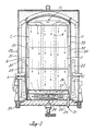
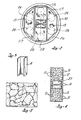
- the assembly 10 of upright open-ended container fixtures 11 is made up of bottom A, middle B, and top C layers of uniform cross-section, in stacked relation. Each layer in turn includes matching or mirror-image pairs of quadrilateral container fixtures, one middle pair 11R rectilinear and the other outside pair 11T trapezoidal.
- the cooperating pairs 11 Rand 11T are configured to fit together side-by-side for a substantially gas-tight fit (as best seen in Figure 2) such that forced convection gas flow through the furnace is tunneled downwardly inside, rather than outside, the fixtures.
- the fixtures are constructed with suitable durable material such as high temperature alloy metal and preferably stainless steel.
- the walls 12 are solid, that is imperforate, and the base 13 contains apertures for passage therethrough of gas, as presently to be described.
- Stainless steel screen is suitable material for the base.
- the fixtures 11 serve not only as containers to structurally support the charge of metal materials to be decarburized in the furnace, but also, when assembled together, as sectional conduits or tunnels through which the downward flow of decarburizing gas is uniformly distributed section-wise during the process.
- the assembly of segment loaded fixtures accommodates a charge density, for example, from 24,04x 10 5 to 40,06x 1 05, preferably about 28,85x10 5 g/m 3 (150 to 250, and preferably about 180, pounds per cubic foot) or higher.
- the loaded array of segments is uniform and permeable throughout the assembly, for purposes of the invention. Also, the loaded segments advantageously do not require mobilizing or mixing during the decarburizing process.
- Another preferred container fixture embodiment seen in Figures 1a and 2a is an open-ended annular container 11 with an inside cylindrical wall 11 a which is concentric with the top surface of the plenum top wall 26.
- Still another preferred container fixture embodiment seen in Figures 1 b and 2b is an annular assembly of two matching open-ended container segments 11 adapted for axial flow registry with the inlet ports 28 of a plenum chamber 25.
- the decarburizing furnace 20 ( Figure 1) is of a type described in the above-mentioned U.S. Patent 3,081,074. It includes a furnace bell 21, radiant heating tubes 22, a base 23, a fan 24, and a plenum chamber 25 with plenum top wall 26 and bottom wall 27.
- the plenum top wall 26 contains plenum inlet ports 28 (as seen in dotted outline in Figure 2) and the bottom wall contains a plenum outlet port 29.
- the cylindrical zone 30 enclosed by the bell 21 and base 23 makes for confined high temperature heating of charges inside the bell.
- a closed-top congruent inner cover 32 defining a furnace chamber or retort 34 is provided in zone 30 for gas-tight fitting upon the base 23 by suitable means such as water/oil seal 35.
- the atmosphere can be controllably altered by introduction on withdrawal of gases at the inlet and outlet port 31.
- the furnace bell and cover each retract from the base and are lifted for purposes of loading and unloading furnace charges.
- the containers 11 are loaded with a furnace charge of scrap steel segments, the bell and cover are replaced, and the closed furnace is cycled through a pre-heat, a decarburizing soak, and finally steps of cooling, opening and unloading.
- the containers of the middle pair 11 R of each layer are each first fitted with a baffle fixture 14 ( Figure 3) positioned as illustrated in Figure 2 so that when loaded with metal segments 15 as illustrated in Figure 4 the load is spaced away from the axial center of the respective layer.
- All containers are then loaded, partly or fully as desired, with segments to provide in each fixture a uniformly gas-permeable array of the segments, it being understood that the steady state pressure drop through the depth of the bed should be substantially uniform for each and all fixtures, and for each stack of fixtures.
- the loading is such that the axial gas flow through the charge is even and uniform thereby avoiding channeling effects which would cause axially and radially spaced pockets or zones of uneven decarburization. Random loading of each fixture is ordinarily sufficient to achieve even distribution of the segments in the fixture. Nesting of the segments should be avoided where possible.
- the bottom layer A is then assembled on the plenum top wall 26 so that each fixture is tightly fitted against the others and is in registry with the respective plenum inlet ports 28.
- the middle layer B and top layer C are each placed, in turn, in stacked fashion onto and in registry with its respective underlying layer to provide the complete assembly illustrated in Figure 1.
- the furance is then cycled through pre-soak, soak and cooling phases.
- the cycle time is a fucntion of furnace size, furnace power, charge weight and density, for example, as follows:
- the chamber 33 is purged with dry nitrogen at 14,15 m 3 (500 cubic feet) per hour (CFH) for two hours while heating to 704°C (1300°F).
- the gas flow is accomplished under convection forced by the fan 24 which blows gas into the annular space 30 upwardly to the top of the container assembly 10 and then downwardly in axial downdraft fashion through the loaded container fixtures 11 to the plenum chamber 25 by way of the inlet ports 28 and radially inward to the plenum outlet 29 and fan 24, thus completing the convection flow cycle.
- the atmosphere is cycled in succession through a natural (DX) gas purge for one hour, a DX gas soak with steam injection for 18 hours, and a nitrogen purge for one hour.
- DX gas purge is done at a flow rate of about 40,06 m 3 /h (250 CFH) and at low dewpoint, e.g. 16°C(60°F) or less.
- the DX gas soak is done at the same flow rate, first at low entering dewpoint followed by an increasing dewpoint, e.g., from 20,5°C (69°F) (2.5% H 2 0 by volume) to about 29,4°C (85°F) exhaust dewpoint (4% H 2 0 by volume).
- the nitrogen purge is done at 80,12 m 3 /h (500 CFH).
- a preferred decarburizing process gas is the so-called rich exothermic gas (Rich EXO: American Gas Association Class 102, air-to-DX gas ratio, about 6.5:1).
- Theoretical analysis of the soak amtosphere is the following: H 2 0-2.5%, H 2 -11 %, CO-8.6%, C0 2 -6.4%, N 2 -balance.
- the retort is pulled and the charge is moved to a cooling stand and cooled preferably at ambient temperature.
- the cooling is carried out by subjecting the charge to a dry nitrogen purge at 40,06 m 3 /h (250 CFH) such that the charge is cooled to about 93,3°C (200°F) in three hours.
- the resulting ferrous metal segments according to the invention typically have the following maximum and preferably weight per cent specifications:
- the invention is applicable broadly to steel scrap segments.
- the average carbon content will ordinarily be at least 0.05% by weight and preferably not more than about 0.2%.
- the segments can have any of a wide variety of shapes and sizes but generally expressed in terms of finished segments the width is at least about 2,54 cm (one inch) and the thickness at least about 1,57 mm (.062 gage). Especially if bulky or rigid, the segments have a maximum dimension of about 20,3 cm (eight inches). Nesting of the segments ordinarily is not a problem. Desirably, the segments may be washed or degreased, and dried prior to decarburizing.
- each segment decarburized according to the invention is unique, as indicated, in that each segment has a generally uniform carbon content. In other words, the carbon content is lowered not only at the surface but at the core and throughout the segment, the average being less than about 0.04%.
- the segments typically are soft and have the grain structure illustrated by Figure 5 showing the micrograph of a core-decarburized product specimen of the process of the invention using 2% Nital etchant at 400x magnification.
- the segments thus have significant advantage as uniformly high quality melt stock for specialty steel making and other purposes.
- the invention contemplates melting the decarburized segments of the invention by means which may be conventional to obtain quality ingots, castings or other forms for remelting, re-rolling or other purposes.
Landscapes
- Engineering & Computer Science (AREA)
- Chemical & Material Sciences (AREA)
- Mechanical Engineering (AREA)
- Materials Engineering (AREA)
- Crystallography & Structural Chemistry (AREA)
- Thermal Sciences (AREA)
- Physics & Mathematics (AREA)
- Metallurgy (AREA)
- Organic Chemistry (AREA)
- General Engineering & Computer Science (AREA)
- Manufacture And Refinement Of Metals (AREA)
- Furnace Details (AREA)
- Heat Treatments In General, Especially Conveying And Cooling (AREA)
Claims (9)
Priority Applications (1)
| Application Number | Priority Date | Filing Date | Title |
|---|---|---|---|
| AT82107372T ATE34777T1 (de) | 1982-02-01 | 1982-08-12 | Behandelte eisenmetalle und verfahren zu ihrer behandlung. |
Applications Claiming Priority (2)
| Application Number | Priority Date | Filing Date | Title |
|---|---|---|---|
| US34446982A | 1982-02-01 | 1982-02-01 | |
| US344469 | 1982-02-01 |
Publications (3)
| Publication Number | Publication Date |
|---|---|
| EP0085136A2 EP0085136A2 (de) | 1983-08-10 |
| EP0085136A3 EP0085136A3 (en) | 1984-03-21 |
| EP0085136B1 true EP0085136B1 (de) | 1988-06-01 |
Family
ID=23350664
Family Applications (1)
| Application Number | Title | Priority Date | Filing Date |
|---|---|---|---|
| EP19820107372 Expired EP0085136B1 (de) | 1982-02-01 | 1982-08-12 | Behandelte Eisenmetalle und Verfahren zu ihrer Behandlung |
Country Status (4)
| Country | Link |
|---|---|
| EP (1) | EP0085136B1 (de) |
| AT (1) | ATE34777T1 (de) |
| CA (1) | CA1204944A (de) |
| DE (2) | DE85136T1 (de) |
Families Citing this family (1)
| Publication number | Priority date | Publication date | Assignee | Title |
|---|---|---|---|---|
| JP2850229B2 (ja) * | 1996-12-17 | 1999-01-27 | 神鋼パンテツク株式会社 | 焼成炉 |
Family Cites Families (9)
| Publication number | Priority date | Publication date | Assignee | Title |
|---|---|---|---|---|
| USRE21500E (en) * | 1940-07-02 | Method of decarbonizing a carbon | ||
| US3127289A (en) * | 1964-03-31 | hoursx | ||
| US2311344A (en) * | 1941-03-04 | 1943-02-16 | Adolph W Machlet | Means for bathing workpieces in a controlled atmosphere |
| FR981416A (fr) * | 1943-04-05 | 1951-05-25 | Procédé de décarburation à l'état solide des aciers au carbene et de certains aciers inoxydables, produits en résultant et leurs applications | |
| GB753001A (en) * | 1953-11-30 | 1956-07-18 | Chromium Mining & Smelting Cor | Improvements in or relating to tray structure for holding a furnace charge |
| US3081074A (en) * | 1957-12-19 | 1963-03-12 | Lee Wilson | Apparatus for annealing coils of strip metal |
| US3196054A (en) * | 1963-08-14 | 1965-07-20 | Armco Steel Corp | Process of decarburizing and annealing of open coil silicon-iron sheet stock without intervening surface treatment |
| DE1508296B2 (de) * | 1966-10-27 | 1970-09-10 | Vereinigte Deutsche Metallwerke AG, 6OOO Prankfurt | Verfahren zum Einschmelzen von Stahlabfällen, die Basisgehalten an Cr, CrNi und CrNiMo aufweisen |
| US4272306A (en) * | 1979-09-27 | 1981-06-09 | Caterpillar Tractor Co. | Carburizing tub apparatus and method |
-
1982
- 1982-08-12 DE DE198282107372T patent/DE85136T1/de active Pending
- 1982-08-12 DE DE8282107372T patent/DE3278570D1/de not_active Expired
- 1982-08-12 AT AT82107372T patent/ATE34777T1/de active
- 1982-08-12 EP EP19820107372 patent/EP0085136B1/de not_active Expired
- 1982-08-19 CA CA000409765A patent/CA1204944A/en not_active Expired
Also Published As
| Publication number | Publication date |
|---|---|
| EP0085136A3 (en) | 1984-03-21 |
| DE3278570D1 (en) | 1988-07-07 |
| ATE34777T1 (de) | 1988-06-15 |
| EP0085136A2 (de) | 1983-08-10 |
| DE85136T1 (de) | 1984-04-12 |
| CA1204944A (en) | 1986-05-27 |
Similar Documents
| Publication | Publication Date | Title |
|---|---|---|
| US6814573B2 (en) | Vacuum heat-treatment apparatus | |
| US2543708A (en) | Heat-treating furnace | |
| US2411073A (en) | Making products of iron or iron alloys | |
| US4497671A (en) | Processed ferrous metal and process of production | |
| US4160680A (en) | Vacuum carburizing | |
| US20050104266A1 (en) | Vacuum furnace with pressurized intensive water quench tank | |
| US4410373A (en) | Process for heat treatment of a metal workpiece | |
| CN110904313A (zh) | 一种箱式天然气球化退火工艺 | |
| US4025610A (en) | Method and apparatus for denitrifying coke | |
| EP0085136B1 (de) | Behandelte Eisenmetalle und Verfahren zu ihrer Behandlung | |
| CN100535170C (zh) | 一种高速工具钢冷拉钢丝成品退火方法 | |
| EP0530513A1 (de) | Wärmebehandlungsofensystem zur gleichzeitigen Durchführung verschiedener Aufkohlungsverfahren | |
| US4223874A (en) | Shaft furnace for producing low-oxygen iron-base metallic powder for powder metallurgy | |
| US3937630A (en) | Method for producing iron-base sintered alloys with high density | |
| US3971679A (en) | Method of annealing oriented silicon steel | |
| US4207120A (en) | Production of metal compacts | |
| JP2842767B2 (ja) | 丸鋼コイルの熱処理炉 | |
| US4175921A (en) | Apparatus for removing gases from particles | |
| US2290552A (en) | Heat treating furnace | |
| US3824122A (en) | Continuous diffusion coating | |
| JPH0645801B2 (ja) | Cr系合金鋼粉の仕上熱処理方法 | |
| US3633649A (en) | Decarburization of ferrous material under low pressure at elevated temperature | |
| US3096174A (en) | Methods of reducing a metal oxide by a carbonaceous material at sub-atmospheric pressures | |
| US1712253A (en) | Heat treatment of steel | |
| GB2134548A (en) | Method for hardening metal workpieces |
Legal Events
| Date | Code | Title | Description |
|---|---|---|---|
| PUAI | Public reference made under article 153(3) epc to a published international application that has entered the european phase |
Free format text: ORIGINAL CODE: 0009012 |
|
| AK | Designated contracting states |
Designated state(s): AT BE CH DE FR GB IT LI LU NL SE |
|
| TCNL | Nl: translation of patent claims filed | ||
| PUAL | Search report despatched |
Free format text: ORIGINAL CODE: 0009013 |
|
| ITCL | It: translation for ep claims filed |
Representative=s name: MODIANO & ASSOCIATI S.R.L. |
|
| EL | Fr: translation of claims filed | ||
| TCAT | At: translation of patent claims filed | ||
| AK | Designated contracting states |
Designated state(s): AT BE CH DE FR GB IT LI LU NL SE |
|
| DET | De: translation of patent claims | ||
| 17P | Request for examination filed |
Effective date: 19840702 |
|
| 17Q | First examination report despatched |
Effective date: 19860421 |
|
| GRAA | (expected) grant |
Free format text: ORIGINAL CODE: 0009210 |
|
| AK | Designated contracting states |
Kind code of ref document: B1 Designated state(s): AT BE CH DE FR GB IT LI LU NL SE |
|
| REF | Corresponds to: |
Ref document number: 34777 Country of ref document: AT Date of ref document: 19880615 Kind code of ref document: T |
|
| REF | Corresponds to: |
Ref document number: 3278570 Country of ref document: DE Date of ref document: 19880707 |
|
| ET | Fr: translation filed | ||
| ITF | It: translation for a ep patent filed | ||
| PLBE | No opposition filed within time limit |
Free format text: ORIGINAL CODE: 0009261 |
|
| STAA | Information on the status of an ep patent application or granted ep patent |
Free format text: STATUS: NO OPPOSITION FILED WITHIN TIME LIMIT |
|
| 26N | No opposition filed | ||
| ITTA | It: last paid annual fee | ||
| PGFP | Annual fee paid to national office [announced via postgrant information from national office to epo] |
Ref country code: GB Payment date: 19920812 Year of fee payment: 11 |
|
| PGFP | Annual fee paid to national office [announced via postgrant information from national office to epo] |
Ref country code: DE Payment date: 19920824 Year of fee payment: 11 |
|
| PGFP | Annual fee paid to national office [announced via postgrant information from national office to epo] |
Ref country code: SE Payment date: 19920826 Year of fee payment: 11 Ref country code: CH Payment date: 19920826 Year of fee payment: 11 |
|
| PGFP | Annual fee paid to national office [announced via postgrant information from national office to epo] |
Ref country code: FR Payment date: 19920827 Year of fee payment: 11 Ref country code: AT Payment date: 19920827 Year of fee payment: 11 |
|
| PGFP | Annual fee paid to national office [announced via postgrant information from national office to epo] |
Ref country code: NL Payment date: 19920831 Year of fee payment: 11 |
|
| PGFP | Annual fee paid to national office [announced via postgrant information from national office to epo] |
Ref country code: LU Payment date: 19920909 Year of fee payment: 11 |
|
| PGFP | Annual fee paid to national office [announced via postgrant information from national office to epo] |
Ref country code: BE Payment date: 19920930 Year of fee payment: 11 |
|
| EPTA | Lu: last paid annual fee | ||
| PG25 | Lapsed in a contracting state [announced via postgrant information from national office to epo] |
Ref country code: LU Free format text: LAPSE BECAUSE OF NON-PAYMENT OF DUE FEES Effective date: 19930812 Ref country code: GB Effective date: 19930812 Ref country code: AT Effective date: 19930812 |
|
| PG25 | Lapsed in a contracting state [announced via postgrant information from national office to epo] |
Ref country code: SE Effective date: 19930813 |
|
| PG25 | Lapsed in a contracting state [announced via postgrant information from national office to epo] |
Ref country code: LI Effective date: 19930831 Ref country code: CH Effective date: 19930831 Ref country code: BE Effective date: 19930831 |
|
| BERE | Be: lapsed |
Owner name: ALLIED IRON CY Effective date: 19930831 |
|
| PG25 | Lapsed in a contracting state [announced via postgrant information from national office to epo] |
Ref country code: NL Effective date: 19940301 |
|
| GBPC | Gb: european patent ceased through non-payment of renewal fee |
Effective date: 19930812 |
|
| NLV4 | Nl: lapsed or anulled due to non-payment of the annual fee | ||
| PG25 | Lapsed in a contracting state [announced via postgrant information from national office to epo] |
Ref country code: FR Effective date: 19940429 |
|
| REG | Reference to a national code |
Ref country code: CH Ref legal event code: PL |
|
| PG25 | Lapsed in a contracting state [announced via postgrant information from national office to epo] |
Ref country code: DE Effective date: 19940503 |
|
| REG | Reference to a national code |
Ref country code: FR Ref legal event code: ST |
|
| EUG | Se: european patent has lapsed |
Ref document number: 82107372.3 Effective date: 19940310 |