EP0085109B1 - Accumulateur au plomb et son procede de fabrication - Google Patents
Accumulateur au plomb et son procede de fabrication Download PDFInfo
- Publication number
- EP0085109B1 EP0085109B1 EP82902206A EP82902206A EP0085109B1 EP 0085109 B1 EP0085109 B1 EP 0085109B1 EP 82902206 A EP82902206 A EP 82902206A EP 82902206 A EP82902206 A EP 82902206A EP 0085109 B1 EP0085109 B1 EP 0085109B1
- Authority
- EP
- European Patent Office
- Prior art keywords
- current collector
- assembly
- winding
- lead
- generating element
- Prior art date
- Legal status (The legal status is an assumption and is not a legal conclusion. Google has not performed a legal analysis and makes no representation as to the accuracy of the status listed.)
- Expired
Links
Images


Classifications
-
- H—ELECTRICITY
- H01—ELECTRIC ELEMENTS
- H01M—PROCESSES OR MEANS, e.g. BATTERIES, FOR THE DIRECT CONVERSION OF CHEMICAL ENERGY INTO ELECTRICAL ENERGY
- H01M10/00—Secondary cells; Manufacture thereof
- H01M10/06—Lead-acid accumulators
- H01M10/12—Construction or manufacture
- H01M10/125—Cells or batteries with wound or folded electrodes
-
- H—ELECTRICITY
- H01—ELECTRIC ELEMENTS
- H01M—PROCESSES OR MEANS, e.g. BATTERIES, FOR THE DIRECT CONVERSION OF CHEMICAL ENERGY INTO ELECTRICAL ENERGY
- H01M4/00—Electrodes
- H01M4/02—Electrodes composed of, or comprising, active material
- H01M4/14—Electrodes for lead-acid accumulators
-
- H—ELECTRICITY
- H01—ELECTRIC ELEMENTS
- H01M—PROCESSES OR MEANS, e.g. BATTERIES, FOR THE DIRECT CONVERSION OF CHEMICAL ENERGY INTO ELECTRICAL ENERGY
- H01M4/00—Electrodes
- H01M4/02—Electrodes composed of, or comprising, active material
- H01M4/64—Carriers or collectors
- H01M4/70—Carriers or collectors characterised by shape or form
-
- Y—GENERAL TAGGING OF NEW TECHNOLOGICAL DEVELOPMENTS; GENERAL TAGGING OF CROSS-SECTIONAL TECHNOLOGIES SPANNING OVER SEVERAL SECTIONS OF THE IPC; TECHNICAL SUBJECTS COVERED BY FORMER USPC CROSS-REFERENCE ART COLLECTIONS [XRACs] AND DIGESTS
- Y02—TECHNOLOGIES OR APPLICATIONS FOR MITIGATION OR ADAPTATION AGAINST CLIMATE CHANGE
- Y02E—REDUCTION OF GREENHOUSE GAS [GHG] EMISSIONS, RELATED TO ENERGY GENERATION, TRANSMISSION OR DISTRIBUTION
- Y02E60/00—Enabling technologies; Technologies with a potential or indirect contribution to GHG emissions mitigation
- Y02E60/10—Energy storage using batteries
-
- Y—GENERAL TAGGING OF NEW TECHNOLOGICAL DEVELOPMENTS; GENERAL TAGGING OF CROSS-SECTIONAL TECHNOLOGIES SPANNING OVER SEVERAL SECTIONS OF THE IPC; TECHNICAL SUBJECTS COVERED BY FORMER USPC CROSS-REFERENCE ART COLLECTIONS [XRACs] AND DIGESTS
- Y02—TECHNOLOGIES OR APPLICATIONS FOR MITIGATION OR ADAPTATION AGAINST CLIMATE CHANGE
- Y02P—CLIMATE CHANGE MITIGATION TECHNOLOGIES IN THE PRODUCTION OR PROCESSING OF GOODS
- Y02P70/00—Climate change mitigation technologies in the production process for final industrial or consumer products
- Y02P70/50—Manufacturing or production processes characterised by the final manufactured product
Definitions
- the invention relates to a method of producing circinately wound lead-acid cells comprising the step of circinately winding a generating element comprising a positive and a negative current collector plate and two active layers separated from each other by use of a winding jig holding the initial end of the generating element and forming a core for the winding.
- a winding jig holding the initial end of the generating element and forming a core for the winding.
- Such method is disclosed, for example, in US-A-3 472 696 where the active layers are provided by embedding, at least partially, active material in paper carrier strips.
- the negative electrode comprises a sheet of lead having paper strips with lead embedded therein on either side; the positive electrode comprises a lead foil strip having paper strips coated with lead peroxide on either side.
- Foils and paper strips are stacked and subsequently rolled up in spiral fashion on a central core or mandrel.
- FR-A-23 91 567 discloses lead-acid cells having thin-walled lead plates or foils the surfaces of which are provided with partial masks which are impermeable for the electrolyte.
- the surfaces of the lead foils which remain free of the masking layers are provided with active material.
- Separators are arranged between foils of opposite polarity. The strength of the masking layers may be increased by glass fibers.
- the lead foils are arranged in plane stacks with the separators in between.
- an object of the invention to improve the known method and to provide an efficient method of producing lead-acid cells having a circinately wound generating element, wherein the elements constituting the generating element can be strongly wound without being damaged.
- this object is attained by a method of producing circinately wound lead-acid cells comprising the step of circinately winding a generating element comprising a positive and a negative current collector plate and two active layers separated from each other by use of a winding jig holding the initial end of the generating element and forming a core for the winding; where the generating element is produced by the following steps:
- the current collector assembly is a part having relatively high mechanical strength, it is possible to firmly hold the current collector assembly by the winding jig. Further, at the start of the winding, the current collector assembly of high mechanical strength is first wound, so that even if this part is bent at a great curvature, there is no danger of the current collector assembly or the separator and active material sheet having a low mechanical strength being broken. Further, the press rollers or the like for imparting a tying force to the generating element in wound condition while winding it can be brought into contact with the current collector assembly of high mechanical strength at all times. For this reason, it is possible, without having to pay any special attention, to effect firm winding and increase the degree of contact of the negative and positive active material sheets with the respective corresponding current collectors.
- said active material sheets include an active material layer and a net-like body of resin embedded in said active material layer.
- FIGs. 1 through 4 the construction and the method of producing a cylindrical lead-acid cell are illustrated.
- two band-like flat plates of lead or lead alloy cut to predescribed size are prepared, serving as a positive current collector 1 and a negative current collector 5.
- These current collectors 1 and 5 are bonded to each other through a thin sheet-like insulator 28 of polyester or the like. In this way, a current collector assembly 29 is formed.
- the insulator 28 may be greater in width than the current collectors 1 and 5. Then, even if the current collectors 1 and 5, when placed one upon the other, are deviated from each other, they can be insulated from each other.
- the net-like body 6 may be made of resin, e.g. of polypropylene, polyethylene, polyester or vinyl chloride and may be a net formed by weaving filaments, as shown in Fig. 5, or, though not shown, it may be a molding in net form.
- the separator 3 is a multi-separator formed of glass fiber.
- an active material sheet assembly 30 including a positive active material sheet assembly 30 including a positive active material layer 2 and a negative active material layer 4 which are laminated with a separator 3 interposed therebetween.
- the active material sheet assembly 30 is placed on one surface of the current collector assembly 29, e.g., the surface where the negative current collector 5 is placed. Then, the negative current collector 5 and the negative active material layer 4 come in contact with each other.
- the generating element composed of the current collector assembly 29 and the active material sheet assembly 30 arranged as shown in Fig. 2 is then wound.
- a winding jig 31 having a cross- sectional shape shown in Fig. 2 is used.
- the winding jig 31 holds one end of the current collector assembly 29, and the generating element is tightly wound by using press rollers (not shown) exerting a suitable pressure, with the winding jig 31 as a core, so that the current collector assembly 29 is disposed outside the active material sheet assembly 30.
- An intermediate stage of the winding operating is shown in Fig. 3.
- the winding jig 31 and the net-like bodies 6 embedded in the active material layers 2 and 4 are omitted from the illustration.
- a cylindrical lead-acid cell having a circinately wound generating element is shown.
- the numeral 32 denotes an electrolytic container lid; and 34 and 35 denote outer terminals.
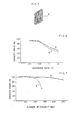
- Figs. 6 and 7 the performances of a lead-acid cell (A) according to this invention and a conventional lead-acid cell (B) are compared.
- the conventional lead-acid cell (B) uses current collectors made of lead or lead alloy in net form by the expand working method.
- Fig. 6 compares the initial characteristics of the lead-acid cells, showing the degree of degradation in capacity (ampere-hours) where the discharge rate is changed from 0.1 C to 2 C, the vertical axis representing the percentage of capacity where the capacity when discharging a current of 0.05 C is taken as 100. As can be seen from Fig.
- Fig. 7 shows the cycle characteristic representing degradation of capacity when charge and discharge are repeated; the conditions for charge and discharge were such that charge was at constant voltage and discharge was effected with a current of 0.2 C, the final voltage for discharge being 1.7 V.
- the following table shows a comparison between the current collectors used in said lead-acid cells (A) and (B), the numerical value for each item being 100 for the current collector obtained by the expand working method.
- the current collector according to this invention is lower in material thickness, weight and price than the conventional one, makes it possible to reduce the weight and size of lead-acid cells and is superior in reduction of cost.
Landscapes
- Chemical & Material Sciences (AREA)
- Chemical Kinetics & Catalysis (AREA)
- Electrochemistry (AREA)
- General Chemical & Material Sciences (AREA)
- Engineering & Computer Science (AREA)
- Manufacturing & Machinery (AREA)
- Secondary Cells (AREA)
- Battery Electrode And Active Subsutance (AREA)
- Cell Electrode Carriers And Collectors (AREA)
Claims (2)
Applications Claiming Priority (10)
| Application Number | Priority Date | Filing Date | Title |
|---|---|---|---|
| JP121009/81 | 1981-07-31 | ||
| JP56121009A JPS5823163A (ja) | 1981-07-31 | 1981-07-31 | 鉛蓄電池 |
| JP1981115765U JPS5821963U (ja) | 1981-08-03 | 1981-08-03 | 鉛蓄電池用陽極板 |
| JP115765/81U | 1981-08-03 | ||
| JP57064541A JPS5823164A (ja) | 1982-04-16 | 1982-04-16 | 鉛蓄電池 |
| JP64541/82 | 1982-04-16 | ||
| JP66954/82U | 1982-05-07 | ||
| JP1982066954U JPS58169668U (ja) | 1982-05-07 | 1982-05-07 | 鉛蓄電池 |
| JP57080493A JPS58197680A (ja) | 1982-05-12 | 1982-05-12 | 渦巻電極体の製造方法 |
| JP80493/82 | 1982-05-12 |
Publications (3)
| Publication Number | Publication Date |
|---|---|
| EP0085109A1 EP0085109A1 (fr) | 1983-08-10 |
| EP0085109A4 EP0085109A4 (fr) | 1984-01-10 |
| EP0085109B1 true EP0085109B1 (fr) | 1988-10-19 |
Family
ID=27523848
Family Applications (1)
| Application Number | Title | Priority Date | Filing Date |
|---|---|---|---|
| EP82902206A Expired EP0085109B1 (fr) | 1981-07-31 | 1982-07-21 | Accumulateur au plomb et son procede de fabrication |
Country Status (4)
| Country | Link |
|---|---|
| US (1) | US4572879A (fr) |
| EP (1) | EP0085109B1 (fr) |
| DE (1) | DE3279142D1 (fr) |
| WO (1) | WO1983000583A1 (fr) |
Families Citing this family (7)
| Publication number | Priority date | Publication date | Assignee | Title |
|---|---|---|---|---|
| FR2576454B1 (fr) * | 1985-01-21 | 1987-05-15 | Sanyo Electric Co | Accumulateur au plomb |
| US4874681A (en) * | 1988-04-14 | 1989-10-17 | Rippel Wally E | Woven-grid sealed quasi-bipolar lead-acid battery construction and fabricating method |
| US4975095A (en) * | 1989-07-28 | 1990-12-04 | Gates Energy Products, Inc. | Method of winding an electrochemical cell and cell produced by the method |
| CA2051614C (fr) * | 1991-09-17 | 1996-01-23 | Michel Gauthier | Collecteurs de courant pour generateurs electrochimiques securitaires, procedes de preparation et generateurs obtenus |
| RU2152111C1 (ru) * | 1995-08-14 | 2000-06-27 | Баотон Саэнс Энд Текнолоджи Сервис Корпорейшн | Электродная пластина свинцового кислотного аккумулятора и способ ее изготовления |
| US8440355B2 (en) * | 2010-01-21 | 2013-05-14 | Tai-Her Yang | Equalizing electrode plate with insulated split-flow conductive structure |
| DE112014006702T5 (de) * | 2014-05-26 | 2017-02-16 | Gs Yuasa International Ltd. | Bleisäurebatterie |
Citations (6)
| Publication number | Priority date | Publication date | Assignee | Title |
|---|---|---|---|---|
| FR325597A (fr) * | ||||
| GB860211A (en) * | 1958-05-21 | 1961-02-01 | Pritchett & Gold & E P S Co | Improvements in or relating to lead-acid type electric accumulators |
| US3472696A (en) * | 1968-07-29 | 1969-10-14 | Mark Shoeld | Storage battery having spiral electrodes with improved active material carrier |
| US3973991A (en) * | 1973-02-13 | 1976-08-10 | Nl Industries, Inc. | Light-weight lead-acid battery with laminated electrodes |
| FR2311414A1 (fr) * | 1975-05-14 | 1976-12-10 | Comp Generale Electricite | Nouvel ensemble de composants pour accumulateur au plomb |
| FR2391567A1 (fr) * | 1977-05-18 | 1978-12-15 | Scholl Dr Ing Gunter | Accumulateur electrique |
Family Cites Families (8)
| Publication number | Priority date | Publication date | Assignee | Title |
|---|---|---|---|---|
| US2834825A (en) * | 1955-03-14 | 1958-05-13 | Ohio Commw Eng Co | Storage batteries, more particularly storage battery plates and method of manufacture |
| JPS4840365B1 (fr) * | 1970-11-24 | 1973-11-30 | ||
| JPS4840365A (fr) * | 1971-09-23 | 1973-06-13 | ||
| DE2710908C3 (de) * | 1977-03-12 | 1980-03-13 | Rheinisch-Westfaelisches Elektrizitaetswerk Ag, 4300 Essen | Verfahren zur Herstellung einer Metall/Kunststoff-Verbundelektrode |
| DE2823725C2 (de) * | 1978-05-31 | 1980-06-19 | Rheinisch-Westfaelisches Elektrizitaetswerk Ag, 4300 Essen | Metallkunststoff-Träger für Elektroden von Akkumulatoren |
| US4221854A (en) * | 1979-02-09 | 1980-09-09 | General Motors Corporation | Lightweight laminated grid for lead-acid storage batteries |
| US4237205A (en) * | 1979-10-22 | 1980-12-02 | General Motors Corporation | Pocket grid for alkaline battery plates |
| US4363857A (en) * | 1981-10-16 | 1982-12-14 | General Motors Corporation | Laminated metal-plastic battery grid |
-
1982
- 1982-07-21 DE DE8282902206T patent/DE3279142D1/de not_active Expired
- 1982-07-21 US US06/482,994 patent/US4572879A/en not_active Expired - Fee Related
- 1982-07-21 EP EP82902206A patent/EP0085109B1/fr not_active Expired
- 1982-07-21 WO PCT/JP1982/000282 patent/WO1983000583A1/fr active IP Right Grant
Patent Citations (6)
| Publication number | Priority date | Publication date | Assignee | Title |
|---|---|---|---|---|
| FR325597A (fr) * | ||||
| GB860211A (en) * | 1958-05-21 | 1961-02-01 | Pritchett & Gold & E P S Co | Improvements in or relating to lead-acid type electric accumulators |
| US3472696A (en) * | 1968-07-29 | 1969-10-14 | Mark Shoeld | Storage battery having spiral electrodes with improved active material carrier |
| US3973991A (en) * | 1973-02-13 | 1976-08-10 | Nl Industries, Inc. | Light-weight lead-acid battery with laminated electrodes |
| FR2311414A1 (fr) * | 1975-05-14 | 1976-12-10 | Comp Generale Electricite | Nouvel ensemble de composants pour accumulateur au plomb |
| FR2391567A1 (fr) * | 1977-05-18 | 1978-12-15 | Scholl Dr Ing Gunter | Accumulateur electrique |
Also Published As
| Publication number | Publication date |
|---|---|
| DE3279142D1 (en) | 1988-11-24 |
| EP0085109A1 (fr) | 1983-08-10 |
| EP0085109A4 (fr) | 1984-01-10 |
| WO1983000583A1 (fr) | 1983-02-17 |
| US4572879A (en) | 1986-02-25 |
Similar Documents
| Publication | Publication Date | Title |
|---|---|---|
| US6419712B1 (en) | Lithium polymer consistent lamination process | |
| US7033701B2 (en) | Lithium secondary cell and method of fabricating the same | |
| US4336314A (en) | Pasted type lead-acid battery | |
| KR100515571B1 (ko) | 중첩 전기 화학 셀 | |
| US6063525A (en) | Source of electrical power for an electric vehicle and other purposes, and related methods | |
| JPH0917441A (ja) | 折曲した電極板を内蔵する角形電池 | |
| CN110783638B (zh) | 一种卷绕堆叠式电芯及其制备方法 | |
| US20230420643A1 (en) | Intermittently coated dry electrode for energy storage device and method of manufacturing the same | |
| EP0085109B1 (fr) | Accumulateur au plomb et son procede de fabrication | |
| US20020150822A1 (en) | Lightweight composite grid for battery plates | |
| US4855196A (en) | Multilaminate material and separator assembly for electrochemical cells | |
| JP2870037B2 (ja) | リチウム負極の製造装置 | |
| US6468687B1 (en) | Alkaline storage battery with reinforced separators | |
| JPH04341766A (ja) | うずまき式密閉形蓄電池 | |
| JP2002075433A (ja) | 電 池 | |
| WO2000008704A1 (fr) | Accumulateur au plomb a bandes en spirales et a elements non circulaires | |
| EP0475999B1 (fr) | Procede pour traiter electrochimiquement la matiere premiere de plaque d'accumulateur | |
| US5348823A (en) | Process of preparing an electrode for an electrochemical cell with a porous support and an electrode obtained by said process | |
| JP2003031225A (ja) | 鉛蓄電池用極板、その製造方法及び鉛蓄電池 | |
| JPH0785885A (ja) | 角形電池 | |
| JPH06223868A (ja) | 密閉式アルカリ蓄電池 | |
| JPH08138726A (ja) | 積層型リチウム二次電池 | |
| JPH10199502A (ja) | セパレータとこれを用いた電池 | |
| EP4300647A1 (fr) | Ensemble électrode et élément de batterie le comprenant | |
| US3679489A (en) | Process for mass production of batteries of electrochemical generators of stacked flat constituents |
Legal Events
| Date | Code | Title | Description |
|---|---|---|---|
| PUAI | Public reference made under article 153(3) epc to a published international application that has entered the european phase |
Free format text: ORIGINAL CODE: 0009012 |
|
| 17P | Request for examination filed |
Effective date: 19830519 |
|
| AK | Designated contracting states |
Designated state(s): CH DE FR GB LI NL |
|
| TCNL | Nl: translation of patent claims filed | ||
| EL | Fr: translation of claims filed | ||
| DET | De: translation of patent claims | ||
| 17Q | First examination report despatched |
Effective date: 19870309 |
|
| GRAA | (expected) grant |
Free format text: ORIGINAL CODE: 0009210 |
|
| AK | Designated contracting states |
Kind code of ref document: B1 Designated state(s): CH DE FR GB LI NL |
|
| REF | Corresponds to: |
Ref document number: 3279142 Country of ref document: DE Date of ref document: 19881124 |
|
| ET | Fr: translation filed | ||
| PLBE | No opposition filed within time limit |
Free format text: ORIGINAL CODE: 0009261 |
|
| STAA | Information on the status of an ep patent application or granted ep patent |
Free format text: STATUS: NO OPPOSITION FILED WITHIN TIME LIMIT |
|
| 26N | No opposition filed | ||
| PGFP | Annual fee paid to national office [announced via postgrant information from national office to epo] |
Ref country code: GB Payment date: 19900711 Year of fee payment: 9 |
|
| PGFP | Annual fee paid to national office [announced via postgrant information from national office to epo] |
Ref country code: FR Payment date: 19900717 Year of fee payment: 9 |
|
| PGFP | Annual fee paid to national office [announced via postgrant information from national office to epo] |
Ref country code: CH Payment date: 19900726 Year of fee payment: 9 |
|
| PGFP | Annual fee paid to national office [announced via postgrant information from national office to epo] |
Ref country code: NL Payment date: 19900731 Year of fee payment: 9 |
|
| PGFP | Annual fee paid to national office [announced via postgrant information from national office to epo] |
Ref country code: DE Payment date: 19900831 Year of fee payment: 9 |
|
| PG25 | Lapsed in a contracting state [announced via postgrant information from national office to epo] |
Ref country code: GB Effective date: 19910721 |
|
| PG25 | Lapsed in a contracting state [announced via postgrant information from national office to epo] |
Ref country code: LI Effective date: 19910731 Ref country code: CH Effective date: 19910731 |
|
| PG25 | Lapsed in a contracting state [announced via postgrant information from national office to epo] |
Ref country code: NL Effective date: 19920201 |
|
| NLV4 | Nl: lapsed or anulled due to non-payment of the annual fee | ||
| GBPC | Gb: european patent ceased through non-payment of renewal fee | ||
| PG25 | Lapsed in a contracting state [announced via postgrant information from national office to epo] |
Ref country code: FR Effective date: 19920331 |
|
| REG | Reference to a national code |
Ref country code: CH Ref legal event code: PL |
|
| PG25 | Lapsed in a contracting state [announced via postgrant information from national office to epo] |
Ref country code: DE Effective date: 19920401 |
|
| REG | Reference to a national code |
Ref country code: FR Ref legal event code: ST |