EP0084861B1 - Laminar multicell lithium batteries - Google Patents
Laminar multicell lithium batteries Download PDFInfo
- Publication number
- EP0084861B1 EP0084861B1 EP83100480A EP83100480A EP0084861B1 EP 0084861 B1 EP0084861 B1 EP 0084861B1 EP 83100480 A EP83100480 A EP 83100480A EP 83100480 A EP83100480 A EP 83100480A EP 0084861 B1 EP0084861 B1 EP 0084861B1
- Authority
- EP
- European Patent Office
- Prior art keywords
- lithium
- cathode
- laminar
- layer
- battery
- Prior art date
- Legal status (The legal status is an assumption and is not a legal conclusion. Google has not performed a legal analysis and makes no representation as to the accuracy of the status listed.)
- Expired
Links
Images


Classifications
-
- H—ELECTRICITY
- H01—ELECTRIC ELEMENTS
- H01M—PROCESSES OR MEANS, e.g. BATTERIES, FOR THE DIRECT CONVERSION OF CHEMICAL ENERGY INTO ELECTRICAL ENERGY
- H01M4/00—Electrodes
- H01M4/02—Electrodes composed of, or comprising, active material
- H01M4/64—Carriers or collectors
- H01M4/66—Selection of materials
- H01M4/665—Composites
- H01M4/666—Composites in the form of mixed materials
-
- H—ELECTRICITY
- H01—ELECTRIC ELEMENTS
- H01M—PROCESSES OR MEANS, e.g. BATTERIES, FOR THE DIRECT CONVERSION OF CHEMICAL ENERGY INTO ELECTRICAL ENERGY
- H01M4/00—Electrodes
- H01M4/02—Electrodes composed of, or comprising, active material
- H01M4/64—Carriers or collectors
- H01M4/66—Selection of materials
- H01M4/665—Composites
- H01M4/667—Composites in the form of layers, e.g. coatings
-
- H—ELECTRICITY
- H01—ELECTRIC ELEMENTS
- H01M—PROCESSES OR MEANS, e.g. BATTERIES, FOR THE DIRECT CONVERSION OF CHEMICAL ENERGY INTO ELECTRICAL ENERGY
- H01M6/00—Primary cells; Manufacture thereof
- H01M6/42—Grouping of primary cells into batteries
- H01M6/46—Grouping of primary cells into batteries of flat cells
- H01M6/48—Grouping of primary cells into batteries of flat cells with bipolar electrodes
-
- H—ELECTRICITY
- H01—ELECTRIC ELEMENTS
- H01M—PROCESSES OR MEANS, e.g. BATTERIES, FOR THE DIRECT CONVERSION OF CHEMICAL ENERGY INTO ELECTRICAL ENERGY
- H01M4/00—Electrodes
- H01M4/02—Electrodes composed of, or comprising, active material
- H01M4/64—Carriers or collectors
- H01M4/66—Selection of materials
- H01M4/663—Selection of materials containing carbon or carbonaceous materials as conductive part, e.g. graphite, carbon fibres
-
- Y—GENERAL TAGGING OF NEW TECHNOLOGICAL DEVELOPMENTS; GENERAL TAGGING OF CROSS-SECTIONAL TECHNOLOGIES SPANNING OVER SEVERAL SECTIONS OF THE IPC; TECHNICAL SUBJECTS COVERED BY FORMER USPC CROSS-REFERENCE ART COLLECTIONS [XRACs] AND DIGESTS
- Y02—TECHNOLOGIES OR APPLICATIONS FOR MITIGATION OR ADAPTATION AGAINST CLIMATE CHANGE
- Y02E—REDUCTION OF GREENHOUSE GAS [GHG] EMISSIONS, RELATED TO ENERGY GENERATION, TRANSMISSION OR DISTRIBUTION
- Y02E60/00—Enabling technologies; Technologies with a potential or indirect contribution to GHG emissions mitigation
- Y02E60/10—Energy storage using batteries
Definitions
- This invention relates to electrical batteries, and particularly to a novel integral multicell lithium battery.
- Lithium batteries have been long known to have potentially superior qualities, such as tolerance for low temperature, high energy density, and long shelf life, but have hitherto been adopted for use only in limited quantities and for highly specialized applications.
- reasons for this limited acceptance have been simple, but compelling; conventional lithium batteries are very expensive, and have a reputation for being dangerous.
- the conventional approach to the design and construction of lithium batteries revolves about a conception of the battery as a single cell encapsulated in a metal container, as of nickel plated steel, and comprising a lithium disc formed integral with a grid of nickel plated steel, or stainless steel, as a current collector.
- the cathode is a solid pressed pellet of any of various reductants held in a metal cup, as by a metal ring. Such a construction is described, for example, in U.A. Patent No. 3,853,627.
- This arrangement has manifest advantages in protecting the cell from mechanical damage; in preventing interactions between potentially reactive components of the atmosphere, such as 0 2 , N 2 , C0 2 , H 2 and H 2 0, and the chemically active cell components; and in ameliorating to some degree the consequences of pressure generated within the cell, either by volatile electrochemical constituents such as S0 2 , or by gases formed in secondary reactions between cell components and contaminants that are formed during storage or are not adequately excluded or removed during cell manufacture.
- the provisions made in this way to ensure cell integrity have significant attendant disadvantages; notable among these are the complexity and consequent cost of the construction, and the potential for explosion caused by excessive internal gassing, internal contaminants, misuse or improper disposal techniques.
- the potential for explosion is inherent in the use of the rigid metal cell container; i.e., in the very expedient adopted to minimize the probability of . potentially explosive reactions.
- each cell consists of a first thin layer, constituting an electronically conductive cathode collector, a second thin layer forming a catholyte comprising a substance suitable for providing anions capable of forming, with the substance of an anode, a discharge product, a third thin layer forming a separator, and a forth thin anode layer, comprising lithium; said catholyte as well as the separator comprise partly a gel impregnated with at least a solvent as well as with an ionically conductive salt; said solvent may be propylene carbonate (PC) or N-methyl pyrrolidone (NMP).
- PC propylene carbonate
- NMP N-methyl pyrrolidone
- the present invention more specifically is concerned with a laminar multicell lithium battery comprising a plurality of stacked contiguous laminar cells electronically connected in series, wherein each cell comprises a lithium anode, a cathode, impregnated with a non-aqueous electrolyte comprising a non-aqueous organic solvent, and a separator between said anode and cathode.
- the objects of the present invention are to simplify the construction and improve the reliability of multicell lithium batteries, without increasing the weight of such batteries, or the volume required to contain them.
- a laminar multicell lithium battery of the general type mentioned in accordance with the invention is characterized in that said non-aqueous electrolyte solvent is selected to act as a passivating agent reactive with lithium for passivating said lithium anode of each cell, each adjacent pair of cells are electronically connected in series and electrochemically isolated only by an electrochemically inert, electronically conducting laminar intercell connector comprising a barrier layer of metal foil impermeable to said passivating electrolyte solvent in contact with the electrochemically active anode and cathode, respectively, of adjacent cells.
- said electrochemically inert, electronically conducting laminar intercell connector comprises said metal foil barrier layer as an inner layer having adhered thereto at its opposite surfaces outer layers of electrochemical inert electronically conducting material; preferably said outer layers of said laminar intercell connector each comprise a conductive plastic layer.
- the metal foil barrier layer of each laminar intercell connector may consist of aluminum.
- the battery cell cathodes may comprise a slurry dispersion of active cathode particles in said electrolyte, comprising an organic solution of a lithium salt containing said passivating solvent, which preferably may comprise propylene carbonate.
- integrally packaged multicell batteries are not broadly new, but have been highly developed in the form of series connected Leclanche cells, as described, for example, in U.S. Patents Nos. 4,105,831 and 4,119,770.
- Such batteries, incorporating aqueous electrolyte systems must be constructed in such a way that a carefully balanced exchange of gases between the cell components and the environment takes place during storage and use, to avoid drastic increases in internal impedance.
- integral multicell laminar batteries of this kind are terminated at the ends by gas and liquid impermeable metal barriers, with the cells being separated by electronically conducting, electrochemically inert barriers of conductive plastic serving as intercell connectors.
- a vent structure such as that described in Patent No. 4,105,831, is incorporated to facilitate the escape of hydrogen while impeding the passage of oxygen and water.
- This structure is operative because the conductive plastic intercell connector, while substantially preventing the passage of anions and cations of the electrolyte, do not prevent the exchange of gases such as O2, N 2 , H 2 or H 2 0 between the cells.
- the organic solvent chosen for the electrolyte should be one in which the chosen electrolyte is relatively soluble and exhibits high ionic activity in solution, and which also reacts to form a passivating film on the lithium anode to inhibit gassing.
- the most popular solvents for this purpose include propylene carbonate, which has both of the desired properties. The passivating effect of this or similar solvents is not fully understood, but is apparently no substantial barrier to ionization of the lithium anode during discharge, although effective to inhibit hydrogen generation upon storage.
- a barrier impermeable to the passivating organic solvent used as a vehicle for the electrolyte must be provided between each cell.
- this barrier preferably takes the form of a thin sheet of metal, such as aluminum, covered on both sides with an electrochemically isolating layer of conductive plastic to prevent interaction between the anode and cathode of adjacent cells and the metal barrier. Since such a barrier inherently acts as an effective gas barrier as well as to block the passage of organic solvent, it will effectively prohibit the gas transport from cell to cell that is required for the proper operation of a multicell Leclanche battery having a vent mechanism in only one cell. However, this is an advantage in a lithium battery in accordance with the invention.
- US-Specification 3 985 574 discloses a non-aqueous two-cell lithium battery system in a common rigid container box without, however, addressing the fore-mentioned specific problems incident in non-aqueous lithium battery systems of the integrated laminar multicell package type.
- the battery known from US ⁇ 3 985 574 no specific intercell connectors are provided, but the two cells of which the battery consists are simply stapled one above the other, with the lithium anode of the lower cell directly contacting the cathode collector of the upper cell.
- PC propylene carbonate
- this solvent will inherently have a passivating effect on the lithium.
- US-Specification 4 204 036 relates to integrated laminar multicell batteries of the non- lithium type, with an aqueous electrolyte system.
- This reference is concerned with a special purpose battery, namely multiple duty batteries having at least three terminals serving as at least two current or voltage sources which can optionally be operated with the two parts of the battery in either parallel or series connection.
- intercell connectors the reference discloses exclusively conductive plastic intercell connectors, in accordance with the general prior art of laminar integrated package batteries.
- This metal current collector sheet is continued externally to form a projecting external terminal tab terminating at the lower surface of the overall battery stack.
- said laminate of a metal collector sheet sandwiched between two conductive plastic layers serves the specific purpose of an intercell terminal assembly to provide the additional (third) terminal required for the three terminal battery with which the reference is concerned.
- Lithium anode assemblies for use in multicell batteries in accordance with the invention may be of any conventional construction. However, presently preferred practice is to laminate a sheet of lithium directly to a suitable conductive plastic substrate in a controlled environment, after first providing a freshly exposed lithium substrate at least on the surface of the lithium sheet to which the conductive plastic substrate is to be adhered.
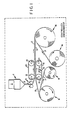
- a billet or ingot of lithium is placed in an hydraulic ram extruder generally designated 1, and there forced through a suitable die, or series of dies, to form an emergent sheet or ribbon 2 of lithium of from 5 to 10 mils (about 0.1 to 0.3 mm) in thickness, and having freshly exposed lithium surfaces.
- the contaminating surface films to be expected on the original ingot will have been removed, or greatly diluted, in the extrusion process, by reason of the greatly increased surface to volume ratio of the extruded foil 2.
- the thickness of the foil 2 may be further reduced, as by driven rolls schematically indicated at 3, to a desired final thickness of from 1 to 3 mils (about .02 to .08 mm).
- the extrusion process should be carried out in a controlled environment schematically suggested at 4 in Fig. 1.
- This environment can be an inert gas, such as argon, but in practice will preferably be dry air at a relative humidity of from 1 to 2 percent.
- the freshly exposed surfaces of the lithium sheet 2 will oxidize in time, even in this environment; thus, it is desirable to carry out the lamination process to be described concurrently with the production of the extruded lithium, rather than, for example, storing the extruded lithium for subsequent lamination.
- the extrusion process carried out in the hydraulic extruder 1 is preferably carried out well below the melting point of lithium (180.5°C), and preferably at about 40°C (104°F).
- the extruder can be kept at constant temperature in the vicinity of this desired operating temperature, as by the circulation of warm water in a suitable heat exchanger formed integral with the extruder housing.
- the operating pressures in the extruder are expected to be in the vicinity of 2000 p.s.i. (13.8x10' KPa).
- the lithium foil 2 is laminated directly to a sheet of conductive plastic 5.
- the conductive plastic 5 should be selected from those materials which can be activated thermally to an adhesive state well below the melting point of lithium, which do not contain species reactive with lithium, which can be prepared in the form of a relatively thin web (e.g., from 2 to 10 mils (about 0.05 to 0.25 mm) in thickness) without an appreciable population of pinholes, which are relatively resistant to the passage of gases such as N 2 , O2, CO 2 , H 2 0 and the like, which possess a relatively low electrical resistivity for current flow across the.
- a presently preferred material for this purpose is prepared in film form by extrusion of poly(ethylene/vinyl acetate) containing from 15 to 22 percent by weight, and preferably 22 percent by weight, of a high surface carbon black such as Ketjenblack EC, a carbon black produced by AKZO Chemie of the Netherlands.
- This material can be laminated to metallic lithium in a hot platen press, at a temperature of about 270°F (about 132°C) with an effective dwell time of at least three and preferably not more than nine seconds under moderate pressure sufficient to maintain the webs in intimate contact.
- the conductive plastic web 5 will be taken from a suitable supply roll 6, on the arbor of which it is wound together with a suitable conventional anti-blocking release sheet 7 of paper, polyester, or the like.
- the release sheet 7 is taken up on a roll 8 for reuse or disposal.
- the lithium web 2 and the conductive plastic web 7 are laminated together by passage through laminating belts 9 and 10, of a material suitable for contact with lithium, such as glass fibers in a polytetrafluoroethylene matrix or the like.
- the belt 9 is carried on a driven roll 11 and an idler roll 12, and the belt 10 is similarly carried on a driven roll 13 and an idler roll 14.
- the rolls 11, 12, 13 and 14 are conventionally mounted to cause the belts 9 and 10 to exert pressure on the intermediate webs 2 and 5 to maintain them in intimate contact during the lamination process.
- Conventional means suggested at 15 are provided to supply heat Q to the belts to maintain the belt 9 at the highest temperature, which may be at or slightly above the melting point of lithium, and the belt 10 at a temperature well below the melting point of lithium, so that the temperature of the lithium component of the laminate will not rise to a level more than 10 to 20°C below its melting point during the laminating process.
- the laminate 2,5 may be cooled in any conventional manner, and then either slit and cut immediately for assembly into batteries in a manner to be described, or taken upon a roll 16 together with a release sheet 17 of paper, polyester or the like from a supply roll 18, for storage and later use.
- Figs. 2-7 illustrate the assembly of a single cell battery.
- the preparation of a multicell battery, to be described below in connection with Fig. 8, may proceed in the same way except as to be noted.
- an insulating base sheet 20 (Figs. 1 and 7), of kraft paper or the like, or most preferably of the material more fully shown and described in U.S. Patent No. 4,086,400, the latter comprising a laminate of kraft paper, a thermoplastic liquid- impervious resin overlying the paper, and an overlayer on the resin of a heat sealing adhesive 21.
- the insulating sheet 20 is provided with an aperture 22 to expose the negative terminal of the battery comprising a sheet 23 of metal, preferably a sheet of aluminum foil, for example, of 2 mils in thickness.
- the metal terminal sheet 23 is laminated to a selected region surrounding the aperture 22 in the insulating sheet 20, and to the peripheral borders of the sheet 20, but is not necessarily, and preferably is not, laminated to the insulating sheet in other regions.
- the upper side of the metal terminal sheet 23 is preferably coated with a thin layer of conductive priming adhesive 24, typically from 0.1 to 0.8 mils (about 0.002 to 0.02 mm) in thickness.
- a conductive priming adhesive typically adherent to the metal and to the conductive plastic 5 of the anode laminate 2,5 can be employed for this purpose, the most suitable being a composition which is essentially the same as that of the web 5, but which contains a thermoplastic constituent containing reactive groups, such as amine, carboxyl, hydroxyl or the like in place of a portion of the ethylene/vinyl acetate constituent of the web 5.
- composition found suitable for this purpose is 70 parts by weight of Cabot XC-72 carbon black dispersed in 100 parts by weight of Vitel VPE-307, a polyester resin made and sold by Goodyear Tire and Rubber Co. of Akron, Ohio.
- This composition is prepared by dissolving the resin in a suitable solvent, such as 80 percent methyl ethyl ketone and 20 percent ethyl acetate, by weight based on the weight of solvent, and dispersing the carbon black in the solution, using sufficient solvent to make a coatable dispersion.
- This composition is coated on the aluminum, and heated to remove the solvent.
- the frame 25 is formed with a central aperture 26 which serves to receive other electrochemically active components in a manner to be described.
- the frame 25 may be of any suitable conventional electrically insulating material that is inert to the constituents of the cell.
- One material that has been successfully employed is a 5 mil (about 0.13 mm) vinyl, specifically a poly(vinyl chloride/ vinyl acetate) containing 85 percent vinyl chloride and 15 percent vinyl acetate by weight, coated on its external surfaces with a poly(ethylene/acrylic acid) adhesive.
- a presently preferred material is nylon coated with a poly(ethylene/vinyl acetate) adhesive.
- An anode electrode structure comprising a sheet 5a of conductive plastic over which a layer 2a of lithium has been laminated in the manner described above is located principally within the aperture 26 formed in the frame 25 and has external borders extending around and over the aperture 26 (Fig. 4), with the conductive plastic sheet 5a being laminated to the edges of the frame 25 around the borders of the aperture 26 and the conductive plastic sheet 5a being laminated to the conductive primer 24 on the conductive metal end terminal sheet 23 as shown in Fig. 7.
- a separator 27 Overlying the anode layer 2a in Fig. 7 is a separator 27 (Figs. 5 and 7) of any conventional material, approximately 2 to 10 mils (about 0.05 to 0.02 mm) in thickness.
- Separators suitable for use in lithium batteries are well known in the art, among those to be considered being polyolefins such as polypropylene, polyethylene, copolymers of propylene and ethylene, mixtures of polyolefins with rubbers such as styrene-butadiene rubber, and the like, together with additives such as Ti0 2 and the like.
- a suitable microporous polypropylene separator is sold under the trademark Celgard by Celanese Plastics Co. of Greer, South Carolina.
- a presently preferred material is a 2 mil (about 0.05 mm) microporous polyolefin separator material of the kind described in U.S. Patent No. 4,287,276, which incorporates a nonionic wetting agent.
- the separator 27 is preferably not fully attached along its periphery to the frame 25, but is only selectively adhered thereto, as by means of stripes of adhesive 28 on either side of the separator along two sides thereof, as shown in dotted lines in Fig. 5.
- the adhesive stripes 21 may be of any selected adhesive material inert to the cell constituents, and for example, of poly(ethylene/vinyl acetate), a polyamide, or the like.
- the separator may be heat-tacked to the frame in discrete regions, as at the corners, to provide sufficient adhesion to carry it through the assembly process.
- the components just described, comprising the insulating sheet 20, the metal terminal sheet 23, the frame 25, the conductive plastic layer 5a with its adherent layer 2a of lithium, and the separator 27, are preferably formed, as a part of a single composite web which acts as an integral subassembly in the process of manufacturing batteries.
- a cathode 29 Overlying the separator 27 in this structure, as seen in Fig. 7, is a cathode 29.
- the cathode may be of any conventional composition and construction, but is preferably formed as a slurry of manganese dioxide and carbon particles in an electrolyte solution in an organic solvent containing a lithium salt as the ionically conductive species.
- Suitable cathode slurry compositions comprise from 50 to 100 parts by weight of propylene carbonate and from 0 to 50 parts by weight of 1,2-dimethoxyethane, based on the weight of solvent, as the organic solvent, with LiAsF e in concentrations of from 0.05 to 2.00 molal, or LiCl0 4 in concentrations of from 0.65 to 1.97 molal, as the electrolyte.
- the electrolyte solution may comprise from 35 to 59 percent by weight, based on the weight of slurry, of a dispersion in the solution of Mn0 2 and carbon black in weight ratios of Mn0 2 to carbon of from 8 to 1 to 24 to 1.
- Examples 2 and 4 are presently preferred cathode formulations.
- the (Kerr-McGee) MnO 2 was heated at 375°C in n furnace for 24 hours under a continuous stream of argon and then stored under vacuum in a glass side arm flask.
- the MnO 2 was redried under vacuum for 6 hours at 160-170 0 C, using an oil bath, before introduction into the batteries.
- the carbon (Cabot XC-72R) was heated to 200°C for 24 hours in a furnace and then stored under vacuum in a glass side arm flask.
- the carbon was redried under vacuum at 160-170 0 C, using an oil bath, for 6 hours before use in batteries.
- LiCl0 4 was dried under vacuum at 180°C, using an oil bath, for 18 hours and then stored under vacuum in a glass side arm flask.
- LiAsF 6 which included traces of water as indicated by an infrared spectrum was dried in the same manner; if no water was found, this material was used as received from the manufacturer.
- the propylene carbonate was refluxed over molecular sieves with 3A pores for a period of twenty four hours, and then distilled at 7375°C under a vacuum corresponding to an absolute pressure of about 0.1 torr. It was then degassed by freezing, evacuation and thawing. The degassing procedure would probably be unnecessary in a production environment, using an atmosphere of dry air at atmospheric pressure.
- the 1,2-dimethoxyethane was also refluxed over molecular sieves for 24 hours, and then distilled at 83-84°C at atmospheric pressure.
- a composite end terminal layer comprising, as shown in Figs. 5, 6 and 7, a sheet of conductive plastic 30, of the same composition as the layer 5a, and for example, of 4 mils (about 0.10 mm) in thickness, laminated to a cathode end terminal sheet 31 of metal, preferably of aluminum foil 2 mils (about 0.05 mm) in thickness and primed on the side adjacent the conductive plastic layer 30 with a thin coat of conductive plastic adhesive 32 employed for the purpose of adhering the conductive plastic sheet 30 to the metal terminal 31 in a manner known in the art per se and described above.
- the end terminal laminate comprising the conductive plastic layer 30, the aluminum sheet 31, and the intermediate conductive plastic priming layer 32 is preferably formed with an extension 33 which is folded around the battery to present a positive terminal on the same side as the negative terminal exposed by the aperture 22.
- this extension can be omitted, as-to facilitate stacking batteries in series to provide a higher operating voltage.
- the battery of Fig. 7 may be sealed under vacuum by heat and pressure applied around the edges, with the proviso that suitably lower temperatures consistent with the materials employed should be utilized.
- nominally pure lithium foil normally has a surface coating of Li 2 0, Li 2 O ⁇ CO 2 or the like, which does not preclude lamination to a conductive plastic substrate of the kind described above.
- surface coating of Li 2 0, Li 2 O ⁇ CO 2 or the like which does not preclude lamination to a conductive plastic substrate of the kind described above.
- the surface of the lithium that is to be placed in contact with the conductive plastic is freshly exposed, as by cleaning with a razor blade, shortly before the lamination is carried out.
- the surface of the lithium that is to be in contact with the electrolyte in the assembled cell is not critical in this regard, as it has been found to make no appreciable difference in the electrical performance of the cell whether or notthis surface is cleaned.
- Fig. 8 shows an exploded view of a three cell lithium battery. As will be apparent to those skilled in the art from the following description, this construction is readily adapted to the manufacture of batteries having any number of cells largerthan one.
- the battery may comprise an anode end terminal half cell 40 which is identical with that described above in connection with Fig. 7.
- the anode end terminal collector may comprise a sheet 41 of a suitable conductive metal, such as 2-mil (about 0.05 mm) aluminum or the like, coated with a thin layer 42 of a conductive plastic adhesive such as that comprising the layer 24 in Fig. 7.
- an insulating frame 43 which may be identical with the frame 25 described above in connection with Figs. 4 and 7.
- the frame 43 is formed with a central aperture 44, corresponding to the aperture 26 in the frame 25.
- An anode electrode structure comprising a sheet 5b of conductive plastic over which a layer 2b of lithium has been laminated in the manner described above is located principally within the aperture 44 formed in the frame 43 and has external borders extending around and over the aperture 44 (Fig. 8), with the conductive plastic sheet 5b being laminated to the edges of the frame 43 around the borders of the aperture 44 and the conductive plastic sheet 5b being laminated to the conductive primer 42 on the conductive metal end terminal sheet 41, identically as for the corresponding elements described above in connection with Fig. 7.
- a separator 45 Overlying the anode layer 2b in Fig. 8 is a separator 45, which may be the same as the separator 27 in Fig. 7.
- the separator 45 is preferably not fully attached along its periphery to the frame 43, but is only selectively adhered thereto in the manner described above in connection with Fig. 5.
- the components of the end terminal half cell assembly 40 just described, comprising the insulating sheet 22, the metal terminal sheet 41, the frame 43, the conductive plastic layer 5b with its adherent layer 2b of lithium, and the separator 45, are preferably adhered to an insulating sheet such as the sheet 22 described above, not shown in Fig. 8, to provide an insulating base for the battery in the manner described above for a single cell battery.
- the cathode end terminal 46 of the battery of Fig. 8 is formed as a laminate of metal foil 47, such as aluminum 2 mils in thickness, coated with a thin coat 48 of a conductive plastic adhesive and thereby laminated to a sheet 49 of a conductive plastic 49.
- This laminate corresponds in structure and function to the end terminal layer comprising the metal end terminal sheet 31 primed with conductive plastic adhesive 32 and laminated to the conductive plastic sheet 30 as described above in connection with Figs. 5, 6 and 7.
- the end terminal 46 may be provided with a projection 49 at one end to be folded around to the other side of the battery, to present the positive terminal on the same side of the battery as the negative terminal.
- intercell subassemblies 50 Between the anode end terminal half cell subassembly 40 and the end terminal 46 at the cathode end of the battery are n-1 intercell subassemblies 50, where n is the total number of cells in the battery.
- Each of the intercell subassemblies 50 may be a subassembly such as 40, to which a layer of conductive plastic is adhered for purposes to appear.
- each subassembly 50 which may be identical with the end terminal subassembly 40 comprises a frame 51, which may be identical with the frame 43 and formed with a central aperture 52 corresponding to the aperture 44 in the frame 43; an anode assembly comprising a lithium foil anode 2c laminated to a conductive plastic sheet 5c corresponding in structure and function to the elements 2b and 5a; a separator 53 corresponding to the separator 45; and a solvent barrier layer 56 which may be of any suitable material which is both electrically conductive and essentially impermeable to the non-aqueous solvent included in the cathode slurry, but which in a preferred embodiment comprises a sheet of metal foil, such as 2 mil (about 0.05 mm) aluminum foil, identical with the metal terminal sheet 41.
- the sheet 56 is suitably adhered to the frame 51 and to confronting regions of the conductive plastic sheet 5c, as by an intermediate layer of conductive plastic adhesive 57, from 0.1 to 0.8 mils (about 0.002 to 0.02 mm) in thickness.
- the edges of the conductive plastic sheets 5c are adhered to the borders of the frames 51 around the apertures 52, and the separators 53 are selectively adhered to portions of the frames 51 only in discrete regions.
- a sheet ofconductive plastic 58 As by an intermediate layer 59 of conductive plastic adhesive.
- These layers 58 and 59 may correspond in structure and composition to the layers 47 and 48 of the end terminal assembly 46; e.g., the layer 58 may be from 3 to 10 mils (about 0.08 to 0.25 mm) in thickness, and preferably from 4 to 6 mils (about 0.10 to 0.15 mm), and the layer 59 from 0.1 to 0.8 mils (about 0.002 to 0.02 mm) and preferably about 0.2 mils (about 0.05 mm) in thickness.
- the battery of Fig. 8 is completed by cathode slurry deposits 60, which may correspond in amount, dimensions and composition to the cathode 29 in Fig. 7.
- the battery may be assembled by adhering the metal terminal sheet 41 forming the base of the subassembly 40 to a nonconductive web such as the base sheet 22, 21 in Fig. 7; depositing the first cathode 60 on the separator 45, as by extrusion; next adding in sequence a subassembly 50, cathode 60, another subassembly 50, another cathode 60, and so on until the assembly is terminated by an end terminal 46.
- the battery is then sealed under vacuum by applying heat and pressure to the edges, to effect a seal between confronting faces of the frames 43 and 51 and the conductive plastic layer 49 of the end terminal 46.
- the frames 51 perform their normal function of providing an electrically insulating barrier against intercell and intracell shorts, and the conductive plastic layers 5c serve to provide electronically conducting, electrochemically isolating barriers.
- the conductive plastic layers 5c serve to provide electronically conducting, electrochemically isolating barriers.
- Such permeation might result in the formation of a highly nonconductive barrier layer; e.g., of Li 2 C0 3 , Li20. CO 2 , or the like; on the lithium anode.
- the degree of such permeation, if any, is not such as to affect the end terminal assemblies such as 46 in Fig. 8, a finding which is harmonizable with the above assumption either on the theory that there is no appreciable reaction between aluminum and the solvents, or that any reaction products of the interaction between aluminum and solvents such as propylene carbonate would be self-limiting films so thin as to oppose no appreciable barrier to electronic conduction.
- the interposition of effective solvent barriers such as 56 has been found to eliminate the high impedance problem.
- the solvent barrier 56 which is preferably of aluminum, does not perform simply as a highly conductive current collector, as does the sheet 41; it would be superfluous if that was its only function. Rather, it is to provide an essentially complete barrier against the passage of organic solvent from a cathode in one cell to the anode in the next adjacent cell.
- the accompanying layer 58 of conductive plastic is needed to isolate the barrier layer 56 from the adjacent cathode 60, and the conductive plastic layers 57 and 59 simply serve to adhere the various layers together sufficiently to prevent delamination in service, while providing a low resistance to the flow of electrical current.
- the shelf life of lithium batteries with Mn0 2 cathodes can be considerably enhanced by a partial electrical discharge of the battery during or immediately after electrochemical assembly (i.e., at least within a few hours of ECA), prior to storage, shipment and sale of the batteries.
- the battery can be connected across a resistor suitable for draining about 20 milliamperes for a time sufficient to remove from 1 to 3 percent of the total capacity of the battery. This practice is preferably followed as a final step in the preparation of batteries in accordance with the invention.
Landscapes
- Chemical & Material Sciences (AREA)
- Engineering & Computer Science (AREA)
- Chemical Kinetics & Catalysis (AREA)
- Electrochemistry (AREA)
- General Chemical & Material Sciences (AREA)
- Materials Engineering (AREA)
- Composite Materials (AREA)
- Manufacturing & Machinery (AREA)
- Primary Cells (AREA)
Applications Claiming Priority (2)
| Application Number | Priority Date | Filing Date | Title |
|---|---|---|---|
| US341196 | 1982-01-20 | ||
| US06/341,196 US4429026A (en) | 1982-01-20 | 1982-01-20 | Laminar multicell lithium batteries |
Publications (2)
| Publication Number | Publication Date |
|---|---|
| EP0084861A1 EP0084861A1 (en) | 1983-08-03 |
| EP0084861B1 true EP0084861B1 (en) | 1989-03-22 |
Family
ID=23336601
Family Applications (1)
| Application Number | Title | Priority Date | Filing Date |
|---|---|---|---|
| EP83100480A Expired EP0084861B1 (en) | 1982-01-20 | 1983-01-20 | Laminar multicell lithium batteries |
Country Status (5)
| Country | Link |
|---|---|
| US (1) | US4429026A (ref) |
| EP (1) | EP0084861B1 (ref) |
| JP (1) | JPS58128665A (ref) |
| CA (1) | CA1191199A (ref) |
| DE (1) | DE3379493D1 (ref) |
Families Citing this family (33)
| Publication number | Priority date | Publication date | Assignee | Title |
|---|---|---|---|---|
| US4502903A (en) * | 1982-01-20 | 1985-03-05 | Polaroid Corporation | Method of making lithium batteries with laminar anodes |
| US5134046A (en) * | 1990-04-04 | 1992-07-28 | Ultralife Batteries, Inc. | Battery with metal foil coated plastic housing |
| US6040085A (en) * | 1994-03-31 | 2000-03-21 | Valence Technology, Inc. | Battery packaging |
| US5670272A (en) * | 1994-03-31 | 1997-09-23 | Valence Technology, Inc. | Battery packaging for flat cell batteries having a compressing material for the cell stack |
| AU3824695A (en) * | 1994-10-13 | 1996-05-06 | Yardney Technical Products, Inc. | Bipolar lithium-ion rechargeable battery |
| US5837397A (en) * | 1996-11-08 | 1998-11-17 | Gould Electronics Inc. | Laminar (flat or paper-type) lithium-ion battery with slurry anodes and slurry cathodes |
| US5792576A (en) * | 1996-11-08 | 1998-08-11 | Gould Electronics Inc. | Limited rechargeable lithium battery based on a cathode slurry |
| US6100702A (en) * | 1997-07-25 | 2000-08-08 | 3M Innovative Properties Company | In-situ fault detection apparatus and method for an encased energy storing device |
| US6117584A (en) * | 1997-07-25 | 2000-09-12 | 3M Innovative Properties Company | Thermal conductor for high-energy electrochemical cells |
| US6120930A (en) | 1997-07-25 | 2000-09-19 | 3M Innovative Properties Corporation | Rechargeable thin-film electrochemical generator |
| US5952815A (en) * | 1997-07-25 | 1999-09-14 | Minnesota Mining & Manufacturing Co. | Equalizer system and method for series connected energy storing devices |
| US6104967A (en) * | 1997-07-25 | 2000-08-15 | 3M Innovative Properties Company | Fault-tolerant battery system employing intra-battery network architecture |
| US6087036A (en) * | 1997-07-25 | 2000-07-11 | 3M Innovative Properties Company | Thermal management system and method for a solid-state energy storing device |
| US6146778A (en) | 1997-07-25 | 2000-11-14 | 3M Innovative Properties Company | Solid-state energy storage module employing integrated interconnect board |
| US6099986A (en) * | 1997-07-25 | 2000-08-08 | 3M Innovative Properties Company | In-situ short circuit protection system and method for high-energy electrochemical cells |
| US5905001A (en) * | 1997-08-13 | 1999-05-18 | Wilson Greatbatch Ltd. | Electrode edge design |
| US6235425B1 (en) | 1997-12-12 | 2001-05-22 | 3M Innovative Properties Company | Apparatus and method for treating a cathode material provided on a thin-film substrate |
| US6277520B1 (en) * | 1999-03-19 | 2001-08-21 | Ntk Powerdex, Inc. | Thin lithium battery with slurry cathode |
| JP3698320B2 (ja) * | 2002-06-03 | 2005-09-21 | 日産自動車株式会社 | 組電池 |
| US8722235B2 (en) * | 2004-04-21 | 2014-05-13 | Blue Spark Technologies, Inc. | Thin printable flexible electrochemical cell and method of making the same |
| EP1787344B1 (en) * | 2004-07-22 | 2017-02-22 | BrightVolt, Inc. | Improved battery tab and packaging design |
| US8029927B2 (en) * | 2005-03-22 | 2011-10-04 | Blue Spark Technologies, Inc. | Thin printable electrochemical cell utilizing a “picture frame” and methods of making the same |
| US8722233B2 (en) * | 2005-05-06 | 2014-05-13 | Blue Spark Technologies, Inc. | RFID antenna-battery assembly and the method to make the same |
| EP2176814A4 (en) * | 2007-07-18 | 2012-06-13 | Blue Spark Technologies Inc | INTEGRATED ELECTRONIC DEVICE AND METHODS OF PREPARATION |
| CN101946347A (zh) * | 2007-12-19 | 2011-01-12 | 蓝色火花科技有限公司 | 高电流薄电化学电池单元及其制造方法 |
| US9027242B2 (en) | 2011-09-22 | 2015-05-12 | Blue Spark Technologies, Inc. | Cell attachment method |
| WO2013177202A1 (en) | 2012-05-21 | 2013-11-28 | Blue Spark Technologies, Inc. | Multi-cell battery |
| EP2914167B1 (en) | 2012-11-01 | 2021-08-04 | Blue Spark Technologies, Inc. | Body temperature logging patch |
| WO2014085604A1 (en) | 2012-11-27 | 2014-06-05 | Blue Spark Technologies, Inc. | Battery cell construction |
| KR101684395B1 (ko) * | 2014-10-02 | 2016-12-08 | 주식회사 엘지화학 | 전도성이 향상된 양극 및 이를 포함하는 이차전지 |
| US9693689B2 (en) | 2014-12-31 | 2017-07-04 | Blue Spark Technologies, Inc. | Body temperature logging patch |
| US10849501B2 (en) | 2017-08-09 | 2020-12-01 | Blue Spark Technologies, Inc. | Body temperature logging patch |
| US20250316800A1 (en) | 2024-04-04 | 2025-10-09 | GM Global Technology Operations LLC | Hybrid battery cell enclosure |
Family Cites Families (11)
| Publication number | Priority date | Publication date | Assignee | Title |
|---|---|---|---|---|
| US3853627A (en) | 1970-10-29 | 1974-12-10 | Accumulateurs Fixes | Lithium electric cells with novel positive active materials and non-aqueous electrolyte |
| GB1362661A (en) * | 1970-12-21 | 1974-08-07 | Esb Inc | Electric batteries formed of stacked lamina-type cells |
| US3985574A (en) * | 1973-05-18 | 1976-10-12 | Compagnie Generale D'electricite | Electrochemical elements in thin layers |
| US4119770A (en) | 1976-05-07 | 1978-10-10 | Polaroid Corporation | Electrical cells and batteries |
| US4105831A (en) | 1977-01-24 | 1978-08-08 | Polaroid Corporation | Vented flat battery |
| US4086400A (en) | 1977-03-30 | 1978-04-25 | Polaroid Corporation | Carrier web for laminar batteries |
| US4169920A (en) * | 1978-12-11 | 1979-10-02 | Gte Laboratories Incorporated | Hermetically sealed electrochemical battery |
| US4204036A (en) | 1979-03-29 | 1980-05-20 | Polaroid Corporation | Multiple duty battery |
| US4287276A (en) | 1979-06-08 | 1981-09-01 | W. R. Grace & Co. | Alkaline battery with separator of high surface area |
| US4269907A (en) * | 1980-05-05 | 1981-05-26 | Lockheed Missiles & Space Company, Inc. | Electrochemical cell |
| US4292380A (en) | 1980-10-23 | 1981-09-29 | Catalyst Research Corporation | Two-cell battery structure |
-
1982
- 1982-01-20 US US06/341,196 patent/US4429026A/en not_active Expired - Fee Related
-
1983
- 1983-01-19 JP JP58007180A patent/JPS58128665A/ja active Granted
- 1983-01-19 CA CA000419830A patent/CA1191199A/en not_active Expired
- 1983-01-20 EP EP83100480A patent/EP0084861B1/en not_active Expired
- 1983-01-20 DE DE8383100480T patent/DE3379493D1/de not_active Expired
Also Published As
| Publication number | Publication date |
|---|---|
| CA1191199A (en) | 1985-07-30 |
| EP0084861A1 (en) | 1983-08-03 |
| JPS58128665A (ja) | 1983-08-01 |
| DE3379493D1 (en) | 1989-04-27 |
| US4429026A (en) | 1984-01-31 |
| JPH0430147B2 (ref) | 1992-05-20 |
Similar Documents
| Publication | Publication Date | Title |
|---|---|---|
| EP0084861B1 (en) | Laminar multicell lithium batteries | |
| US4502903A (en) | Method of making lithium batteries with laminar anodes | |
| EP0084381B1 (en) | Lithium batteries with organic slurry cathodes | |
| US4477544A (en) | Intercell connector for lithium batteries | |
| US4621035A (en) | Lithium batteries with laminar anodes | |
| CA2011720C (en) | Battery in a vacuum sealed enveloping material and a process for making the same | |
| US4977046A (en) | Lithium batteries | |
| CN100452527C (zh) | 锂离子二次电池 | |
| US10033048B2 (en) | Thin film battery | |
| US6287719B1 (en) | Battery including a non-aqueous multi-cell spiral-wound electrode assembly | |
| EP0862227B1 (en) | Thin type electric cell | |
| EP0973212B1 (en) | Nonaqueous thin battery | |
| KR100430123B1 (ko) | 비수전해질전지 및 그 제조법 | |
| US4525439A (en) | Connector aperture seal for a galvanic cell | |
| EP1032068B1 (en) | Solid electrolyte battery | |
| US20040241537A1 (en) | Air battery | |
| US6103416A (en) | Laminated lithium-ion cell and process for fabricating same | |
| JPS6145356B2 (ref) | ||
| US4732825A (en) | Flat cell | |
| US4579792A (en) | Lithium batteries with organic slurry cathodes | |
| US4173066A (en) | Methods for making laminar cells | |
| JPH10261386A (ja) | 電池用外装体および電池 | |
| US8221509B2 (en) | Battery and method for producing the same | |
| EP3465813A1 (en) | Devices | |
| CA1077127A (en) | Bonded component assembly for flat cells and method therefor |
Legal Events
| Date | Code | Title | Description |
|---|---|---|---|
| PUAI | Public reference made under article 153(3) epc to a published international application that has entered the european phase |
Free format text: ORIGINAL CODE: 0009012 |
|
| AK | Designated contracting states |
Designated state(s): DE FR GB NL |
|
| 17P | Request for examination filed |
Effective date: 19840202 |
|
| GRAA | (expected) grant |
Free format text: ORIGINAL CODE: 0009210 |
|
| AK | Designated contracting states |
Kind code of ref document: B1 Designated state(s): DE FR GB NL |
|
| REF | Corresponds to: |
Ref document number: 3379493 Country of ref document: DE Date of ref document: 19890427 |
|
| ET | Fr: translation filed | ||
| PLBE | No opposition filed within time limit |
Free format text: ORIGINAL CODE: 0009261 |
|
| STAA | Information on the status of an ep patent application or granted ep patent |
Free format text: STATUS: NO OPPOSITION FILED WITHIN TIME LIMIT |
|
| 26N | No opposition filed | ||
| PGFP | Annual fee paid to national office [announced via postgrant information from national office to epo] |
Ref country code: FR Payment date: 19941212 Year of fee payment: 13 |
|
| PGFP | Annual fee paid to national office [announced via postgrant information from national office to epo] |
Ref country code: DE Payment date: 19941215 Year of fee payment: 13 |
|
| PGFP | Annual fee paid to national office [announced via postgrant information from national office to epo] |
Ref country code: GB Payment date: 19941216 Year of fee payment: 13 |
|
| PGFP | Annual fee paid to national office [announced via postgrant information from national office to epo] |
Ref country code: NL Payment date: 19950131 Year of fee payment: 13 |
|
| PG25 | Lapsed in a contracting state [announced via postgrant information from national office to epo] |
Ref country code: GB Effective date: 19960120 |
|
| PG25 | Lapsed in a contracting state [announced via postgrant information from national office to epo] |
Ref country code: NL Effective date: 19960801 |
|
| GBPC | Gb: european patent ceased through non-payment of renewal fee |
Effective date: 19960120 |
|
| PG25 | Lapsed in a contracting state [announced via postgrant information from national office to epo] |
Ref country code: FR Effective date: 19960930 |
|
| NLV4 | Nl: lapsed or anulled due to non-payment of the annual fee |
Effective date: 19960801 |
|
| PG25 | Lapsed in a contracting state [announced via postgrant information from national office to epo] |
Ref country code: DE Effective date: 19961001 |
|
| REG | Reference to a national code |
Ref country code: FR Ref legal event code: ST |