EP0084338B1 - Boîtier pour batterie de générateurs électrochimiques - Google Patents
Boîtier pour batterie de générateurs électrochimiques Download PDFInfo
- Publication number
- EP0084338B1 EP0084338B1 EP83100161A EP83100161A EP0084338B1 EP 0084338 B1 EP0084338 B1 EP 0084338B1 EP 83100161 A EP83100161 A EP 83100161A EP 83100161 A EP83100161 A EP 83100161A EP 0084338 B1 EP0084338 B1 EP 0084338B1
- Authority
- EP
- European Patent Office
- Prior art keywords
- casing
- modules
- casings
- cavities
- complementary
- Prior art date
- Legal status (The legal status is an assumption and is not a legal conclusion. Google has not performed a legal analysis and makes no representation as to the accuracy of the status listed.)
- Expired - Lifetime
Links
Images
Classifications
-
- H—ELECTRICITY
- H01—ELECTRIC ELEMENTS
- H01M—PROCESSES OR MEANS, e.g. BATTERIES, FOR THE DIRECT CONVERSION OF CHEMICAL ENERGY INTO ELECTRICAL ENERGY
- H01M50/00—Constructional details or processes of manufacture of the non-active parts of electrochemical cells other than fuel cells, e.g. hybrid cells
- H01M50/20—Mountings; Secondary casings or frames; Racks, modules or packs; Suspension devices; Shock absorbers; Transport or carrying devices; Holders
- H01M50/204—Racks, modules or packs for multiple batteries or multiple cells
- H01M50/207—Racks, modules or packs for multiple batteries or multiple cells characterised by their shape
- H01M50/213—Racks, modules or packs for multiple batteries or multiple cells characterised by their shape adapted for cells having curved cross-section, e.g. round or elliptic
-
- Y—GENERAL TAGGING OF NEW TECHNOLOGICAL DEVELOPMENTS; GENERAL TAGGING OF CROSS-SECTIONAL TECHNOLOGIES SPANNING OVER SEVERAL SECTIONS OF THE IPC; TECHNICAL SUBJECTS COVERED BY FORMER USPC CROSS-REFERENCE ART COLLECTIONS [XRACs] AND DIGESTS
- Y02—TECHNOLOGIES OR APPLICATIONS FOR MITIGATION OR ADAPTATION AGAINST CLIMATE CHANGE
- Y02E—REDUCTION OF GREENHOUSE GAS [GHG] EMISSIONS, RELATED TO ENERGY GENERATION, TRANSMISSION OR DISTRIBUTION
- Y02E60/00—Enabling technologies; Technologies with a potential or indirect contribution to GHG emissions mitigation
- Y02E60/10—Energy storage using batteries
Definitions
- the present invention relates to a housing for a battery of primary or secondary electrochemical generators according to the preamble of claim 1.
- a housing is known, for example from document US-A-4,123,598.
- the purpose of the present invention is to produce a housing which can be used for generators whether or not provided with an insulating sheath and which makes it possible to dispense with numerous tools, as well as attachment accessories of the glue, link, ribbon, etc. type. and this, whatever the number of generators.
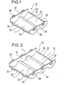
- an insulating module 2 with two cavities 1 in cylinder portion separated by an intermediate rib 21; its extreme edges 22 and 23 have complementary portions 24-25 which are capable of cooperating with the edge of another juxtaposed module; the module 2 comprises two bases 26 and 27 orthogonal to the generatrices of the cavities 1 and provided respectively with additional hooking means 28 and 29 of the lug-buttonhole type.
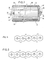
- FIG 2 we see an insulating module 3 with three cavities 1; the ribs 31 are similar to the rib 21 of the module 1.
- the end edges 32 and 33 have dovetail portions 24 and 25 and the bases 36 and 37 carry attachment means 28 and 29.
- An assembly is provided 28-29 opposite each cavity 1.
- the housing is closed at its ends by two insulating plates (not shown) cooperating with the assemblies 24 and 25 of the extreme edges of the modules 3 and 2.
- a metal terminal outlet from the housing or any other variant of the tab, cable or similar type can be provided for connection to consumers.
- Reference 50 is an electrochemical generator.
- the modules 2 and 3 make it possible to produce a box comprising any number of generators, and this, without it being necessary to implement accessories for complex and specific joining of this number of generators.
- FIG. 4 very schematically shows a box for five generators comprising an upper half-box consisting of a module 3 followed by a module 2 and a lower half-box consisting of a module 2 followed by a module 3.
- FIG. 5 shows a box for six generators comprising an upper half-box made up of two modules 3 and a lower half-box made up of three modules 2.
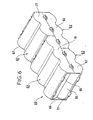
- FIG. 6 shows a box 60 making it possible to contain two rows 65 and 66 of juxtaposed generators.
- the upper half-casing comprises a module 63 with three elements followed by a module 62 with two elements, while the lower half-casing comprises a module 62 followed by a module 63.
- the modules 62 and 63 are identical in all respects to the modules 2 and 3 previously described, except at the level of their bases 67, 68, 77 and 78, the height of which is chosen as a function of the height of the stack of the rows 65 and 66
- the means of attachment of the modules are unchanged.
- the lug-buttonhole and dovetail assemblies can be replaced by any equivalent assembly method.
Description
- La présente invention concerne un boîtier pour batterie de générateurs électrochimiques primaires ou secondaires selon le préambule de la revendication 1. Un tel boîtier est connu, par exemple à partir du document US-A-4.123.598.
- Il est indispensable de maintenir entre deux générateurs voisins une distance d'isolement suffisante. Ainsi, on connaît par le brevet français n° 2 369 693 des boîtiers comportant un bac fermé par un couvercle et présentant des compartiments internes séparant les générateurs les uns des autres; il est clair qu'il faut prévoir un type de boîtier pour chaque batterie comportant un nombre donné de générateurs. A ce sujet, ledit document US-A propose d'interposer des cales entre deux générateurs, si la longueur d'un compartiment excède celle de l'ensemble des générateurs à y loger.
- La présente invention a pour but de réaliser un boîtier utilisable pour des générateurs munis ou non d'une gaine isolante et permettant de s'affranchir de nombreux outillages, ainsi que des accessoires de solidarisation du genre colle, lien, ruban, etc... et ceci, quel que soit le nombre de générateurs.
- Ce but est atteint selon l'invention par le boîtier tel qu'il est défini dans la revendication 1. En ce qui concerne des caractéristiques d'une mise en oeuvre préférée de l'invention, référence est faite aux revendications secondaires.
- L'invention sera décrite ci-après, à titre illustratif mais nullement limitatif, à l'aide de quelques exemples de réalisation dans lesquels on a choisi n = 2.
- Dans le dessin annexé:
- la figure 1 illustre en perspective un module à deux cavités,
- la figure 2 illustre en perspective un module à trois cavités,
- la figure 3 montre en coupe partielle transversale un boîtier selon l'invention,
- la figure 4 montre schématiquement d'en face un boîtier selon l'invention contenant cinq générateurs en une rangée,
- la figure 5 montre schématiquement d'en face un autre boîtier selon l'invention contenant six générateurs en une rangée,
- la figure 6 montre en perspective un boîtier selon l'invention susceptible de contenir deux rangées de générateurs.
- On voit sur la figure 1 un module isolant 2 à deux cavités 1 en portion de cylindre séparées par une nervure intermédiaire 21; ses bords extrêmes 22 et 23 présentent des portions complémentaires 24-25 qui sont susceptibles de coopérer avec le bord d'un autre module juxtaposé; le module 2 comporte deux bases 26 et 27 orthogonales aux génératrices des cavités 1 et munis respectivement de moyens d'accrochage complémentaires 28 et 29 de type ergot-boutonnière.
- Sur la figure 2, on voit un module isolant 3 à trois cavités 1; les nervures 31 sont analogues à la nervure 21 du module 1. Les bords extrêmes 32 et 33 présentent des portions en queue d'aronde 24 et 25 et les bases 36 et 37 portent des moyens d'accrochage 28 et 29. On prévoit un ensemble 28-29 en regard de chaque cavité 1.
- Le boîtier est fermé à ses extrémités par deux plaquettes isolantes (non représentées) coopérant avec les assemblages 24 et 25 des bords extrêmes des modules 3 et 2. Une cosse métallique de sortie du boîtier ou toute autre variante de type languette, câble ou analogue peut être prévue pour la connexion à des consommateurs.
- On voit de façon plus précise sur la figure 3 comment les modules 2 ou 3 constituant le demi-boîtier supérieur sont accrochés aux modules 2 ou 3 constituant le demi-boîtier inférieur 3. On a référencé 50 un générateur électrochimique.
- Les modules 2 et 3 permettent de réaliser un boîtier comportant un nombre quelconque de générateurs, et ceci, sans qu'il soit nécessaire de mettré en oeuvre des accessoires de solidarisation complexes et spécifiques de ce nombre de générateurs.
- La figure 4 montre très schématiquement un boîtier pour cinq générateurs comportant un demi-boîtier supérieur constitué d'un module 3 suivi d'un module 2 et un demi-boîtier inférieur constitué d'un module 2 suivi d'un module 3.
- La figure 5 montre un boîtier pour six générateurs comportant un demi-boîtier supérieur constitué de deux modules 3 et un demi-boîtier inférieur constitué de trois modules 2.
- Une pluralité d'autres combinaisons est possible bien entendu en choisissant n > 2.
- On a représenté sur la figure 6 un boîtier 60 permettant de contenir deux rangées 65 et 66 de générateurs juxtaposés.
- Le demi-boîtier supérieur comporte un module 63 à trois éléments suivi d'un module 62 à deux éléments, tandis que le demi-boîtier inférieur comporte un module 62 suivi d'un module 63.
- Les modules 62 et 63 sont en tous points identiques aux modules 2 et 3 précédemment décrits, sauf au niveau de leurs bases 67, 68, 77 et 78 dont la hauteur est choisie en fonction de la hauteur de l'empilement des rangées 65 et 66. Les moyens d'accrochage des modules sont inchangés.
- Les assemblages ergot-boutonnière et queue- d'aronde peuvent être remplacés par tout mode d'assemblage équivalent.
Claims (6)
Priority Applications (1)
| Application Number | Priority Date | Filing Date | Title |
|---|---|---|---|
| AT83100161T ATE54387T1 (de) | 1982-01-14 | 1983-01-11 | Behaelter fuer elektrochemische batterien. |
Applications Claiming Priority (2)
| Application Number | Priority Date | Filing Date | Title |
|---|---|---|---|
| FR8200528A FR2519804A1 (fr) | 1982-01-14 | 1982-01-14 | Boitier pour batterie de generateurs electrochimiques |
| FR8200528 | 1982-01-14 |
Publications (2)
| Publication Number | Publication Date |
|---|---|
| EP0084338A1 EP0084338A1 (fr) | 1983-07-27 |
| EP0084338B1 true EP0084338B1 (fr) | 1990-07-04 |
Family
ID=9269988
Family Applications (1)
| Application Number | Title | Priority Date | Filing Date |
|---|---|---|---|
| EP83100161A Expired - Lifetime EP0084338B1 (fr) | 1982-01-14 | 1983-01-11 | Boîtier pour batterie de générateurs électrochimiques |
Country Status (8)
| Country | Link |
|---|---|
| US (1) | US4510215A (fr) |
| EP (1) | EP0084338B1 (fr) |
| AT (1) | ATE54387T1 (fr) |
| CA (1) | CA1189567A (fr) |
| DE (1) | DE3381697D1 (fr) |
| ES (1) | ES277375Y (fr) |
| FR (1) | FR2519804A1 (fr) |
| YU (1) | YU44215B (fr) |
Families Citing this family (41)
| Publication number | Priority date | Publication date | Assignee | Title |
|---|---|---|---|---|
| US4806440A (en) * | 1987-02-05 | 1989-02-21 | Cni | Lantern battery substitute |
| US5308717A (en) * | 1992-02-12 | 1994-05-03 | S & K Racing Products, Inc. | Battery jig |
| US5431575A (en) * | 1994-02-18 | 1995-07-11 | Cardiac Evaluation Center, Inc. | Bi-directional battery holder |
| US5536595A (en) * | 1994-09-30 | 1996-07-16 | Globe-Union Inc. | Split shell battery enclosure |
| EP0907973B1 (fr) * | 1997-02-21 | 2002-05-08 | Volvo Aero Corporation | Convertisseur thermoelectrique |
| JP3863693B2 (ja) | 1999-02-01 | 2006-12-27 | 松下電器産業株式会社 | パック電池 |
| US6410185B1 (en) * | 1999-02-15 | 2002-06-25 | Sony Corporation | Battery device for loading on moving body |
| US6196755B1 (en) | 1999-05-06 | 2001-03-06 | Corning Incorporated | Locking device for projection television lens assembly |
| US6285416B1 (en) | 1999-05-06 | 2001-09-04 | Corning Precision Lens | Apparatus and method for a focus position lock device for a projection television lens assembly |
| ES2179734B1 (es) * | 2000-06-13 | 2004-04-01 | SOCIEDAD ESPAñOLA DEL ACUMULADOR TUDOR, S.A. | Baterias de acumuladores electricos. |
| US6600612B2 (en) | 2001-05-15 | 2003-07-29 | 3M Innovative Properties Company | Lens system having resilient members to axially position optics |
| US6441976B1 (en) | 2001-05-15 | 2002-08-27 | Corning Precision Lens, Inc. | Lens system having compliant optic mounting structure |
| JP4351407B2 (ja) * | 2001-09-18 | 2009-10-28 | 富士通株式会社 | 携帯型情報処理装置 |
| US7332243B2 (en) * | 2003-01-09 | 2008-02-19 | Johnson Controls Technology Company | Battery and battery container |
| US20060110657A1 (en) * | 2004-11-15 | 2006-05-25 | William Stanton | Battery assembly for use in an uninterruptible power supply system and method |
| WO2007030154A1 (fr) * | 2005-09-02 | 2007-03-15 | Tools Aviation, Llc | Conteneur-distributeur de piles eclaire |
| US7287648B2 (en) * | 2005-09-02 | 2007-10-30 | Tools Aviation, Llc | Battery holder and dispenser |
| KR100930474B1 (ko) * | 2005-12-08 | 2009-12-09 | 주식회사 엘지화학 | 전지모듈 제조용 조립식 스페이서 |
| JP4767009B2 (ja) * | 2005-12-14 | 2011-09-07 | 日立ビークルエナジー株式会社 | 組電池 |
| CN101820053B (zh) * | 2005-12-27 | 2012-12-19 | 株式会社Lg化学 | 电池组间隔件 |
| KR100874055B1 (ko) | 2007-01-25 | 2008-12-12 | 삼성에스디아이 주식회사 | 단위 전지간 인터커넥터 및 이를 구비한 직렬 전지 |
| KR100949333B1 (ko) | 2007-11-12 | 2010-03-26 | 삼성에스디아이 주식회사 | 전지 모듈 |
| US9077056B2 (en) * | 2007-12-11 | 2015-07-07 | Battery Patent Trust | Device for housing electrochemical cells |
| US9184425B2 (en) * | 2009-01-13 | 2015-11-10 | Samsung Sdi Co., Ltd. | Battery pack |
| US8293392B2 (en) * | 2009-03-26 | 2012-10-23 | Sanyo Energy (Usa) Corporation | Battery holder for a battery array, and battery array |
| JP5063646B2 (ja) * | 2009-07-31 | 2012-10-31 | パナソニック株式会社 | 電池パック用ケース、その製造方法、電池パック及びその製造方法 |
| US8609274B2 (en) * | 2010-03-24 | 2013-12-17 | Bren-Tronics Batteries International, L.L.C. | Nested heatsink housing for lithium ion cells |
| US8291567B1 (en) | 2010-08-25 | 2012-10-23 | The United States Of America As Represented By The Secretary Of The Navy | Method for maximizing packing density with cylindrical objects in cylindrical cavities |
| USD660790S1 (en) | 2011-10-25 | 2012-05-29 | Johnson Controls Technology Company | Battery |
| USD660232S1 (en) | 2011-10-25 | 2012-05-22 | Johnson Controls Technology Company | Battery |
| USD660226S1 (en) | 2011-10-25 | 2012-05-22 | Johnson Controls Technology Company | Battery |
| USD668604S1 (en) | 2011-10-25 | 2012-10-09 | Johnson Controls Technology Company | Battery |
| USD668217S1 (en) * | 2012-02-23 | 2012-10-02 | Hewlett-Packard Development Company, L.P. | Battery pack |
| US8927137B2 (en) | 2012-05-01 | 2015-01-06 | Microsun Technologies Llc | Fail safe damage resistant battery matrix |
| US20140017536A1 (en) * | 2012-07-11 | 2014-01-16 | Cheng-Ji Lu | Battery assembly device |
| CN107732305B (zh) * | 2016-08-11 | 2020-07-24 | 神讯电脑(昆山)有限公司 | 活动电木托盘治具 |
| CN113675516B (zh) * | 2016-11-16 | 2024-02-13 | 奥动新能源汽车科技有限公司 | 导电片、动力电池模块及动力电池箱 |
| USD830965S1 (en) | 2017-01-27 | 2018-10-16 | Johnson Controls Technology Company | Battery case with cover |
| KR102059614B1 (ko) * | 2017-11-14 | 2019-12-26 | 주식회사 엘지화학 | 고정부를 포함하는 배터리 팩 |
| KR102120933B1 (ko) * | 2019-09-06 | 2020-06-09 | 주식회사 알멕 | 전기자동차용 배터리 모듈 케이스 |
| EP3799195A1 (fr) * | 2019-09-27 | 2021-03-31 | Proterra Inc. | Logement de batterie |
Family Cites Families (8)
| Publication number | Priority date | Publication date | Assignee | Title |
|---|---|---|---|---|
| US3181974A (en) * | 1962-05-16 | 1965-05-04 | Barb Inc | Releasable battery clip |
| FR1336265A (fr) * | 1962-07-20 | 1963-08-30 | Wonder Piles | Boîte de raccordement pour pile ronde |
| NL133412C (fr) * | 1964-06-16 | |||
| CA1029437A (fr) * | 1973-12-14 | 1978-04-11 | P.R. Mallory And Co. Inc. | Gaine d'accumulateur jetable |
| FR2369693A1 (fr) * | 1976-10-26 | 1978-05-26 | Accumulateurs Fixes | Boitier coupleur pour piles electriques |
| US4123598A (en) * | 1978-04-24 | 1978-10-31 | The Gates Rubber Company | Battery pack and container |
| US4383007A (en) * | 1980-06-23 | 1983-05-10 | General Electric Company | Battery compartment |
| US4407911A (en) * | 1980-10-01 | 1983-10-04 | General Electric Company | Rechargeable electrochemical cell pack having resistance to impact and vibration |
-
1982
- 1982-01-14 FR FR8200528A patent/FR2519804A1/fr active Granted
- 1982-12-10 US US06/448,628 patent/US4510215A/en not_active Expired - Fee Related
- 1982-12-20 YU YU2806/82A patent/YU44215B/xx unknown
-
1983
- 1983-01-11 AT AT83100161T patent/ATE54387T1/de not_active IP Right Cessation
- 1983-01-11 EP EP83100161A patent/EP0084338B1/fr not_active Expired - Lifetime
- 1983-01-11 DE DE8383100161T patent/DE3381697D1/de not_active Expired - Fee Related
- 1983-01-13 CA CA000419391A patent/CA1189567A/fr not_active Expired
- 1983-01-13 ES ES1983277375U patent/ES277375Y/es not_active Expired
Also Published As
| Publication number | Publication date |
|---|---|
| FR2519804A1 (fr) | 1983-07-18 |
| EP0084338A1 (fr) | 1983-07-27 |
| FR2519804B1 (fr) | 1984-03-09 |
| ES277375U (es) | 1984-10-16 |
| YU44215B (en) | 1990-04-30 |
| US4510215A (en) | 1985-04-09 |
| ATE54387T1 (de) | 1990-07-15 |
| DE3381697D1 (de) | 1990-08-09 |
| ES277375Y (es) | 1985-04-16 |
| CA1189567A (fr) | 1985-06-25 |
| YU280682A (en) | 1984-12-31 |
Similar Documents
| Publication | Publication Date | Title |
|---|---|---|
| EP0084338B1 (fr) | Boîtier pour batterie de générateurs électrochimiques | |
| EP2034539B1 (fr) | Batterie constituée d'une pluralité de cellules positionnées et reliées entre elles, sans soudure | |
| WO2010061063A1 (fr) | Systeme d'assemblage de modules d'energie electrique | |
| EP0059496B1 (fr) | Dispositif électrochimique comportant au moins 2 éléments réunis en série électrique | |
| FR2562722A1 (fr) | Procede et dispositif pour la fabrication d'un ensemble accumulateur electrique comprenant une pluralite d'elements accumulateurs rechargeables | |
| EP1047139A1 (fr) | Source d'alimentation en courant continu pour véhicule à moteur électrique | |
| JP6394964B2 (ja) | 蓄電モジュール | |
| EP1376638B1 (fr) | Ensemble de protection et de commande électromagnétique | |
| EP0498151B1 (fr) | Réglette de raccordement à protections semi-intégrées | |
| FR2703840A1 (fr) | Connecteur électrique pourvu d'une pluralité de modules de connexion disposés en lignes et colonnes. | |
| FR2970456A1 (fr) | Engin ferroviaire comprenant au moins un module extractible de batteries. | |
| EP2849295B1 (fr) | Ensemble de distribution électrique comportant un peigne multipolaire de répartition d une énergie électrique. | |
| EP0704874B1 (fr) | Interrupteur différentiel associé à un ou plusieurs éléments de protection de circuit tels des coupe-circuits à fusibles ou disjoncteurs | |
| EP3903363B1 (fr) | Module de batterie electrique et batterie comportant au moins un tel module | |
| FR2761545A1 (fr) | Motoventilateur pour vehicule automobile avec connecteur vers le vehicule | |
| EP1166376B1 (fr) | Coffre pour ensemble de batteries d'accumulateurs electriques | |
| FR3127637A1 (fr) | Dispositif de protection pour accumulateur électrochimique prismatique | |
| FR2499774A1 (fr) | Bloc de pile a combustible constitue d'un empilement d'elements creux portant des electrodes | |
| EP0635902A1 (fr) | Borne de contact et module connecteur électrique | |
| FR2748608A1 (fr) | Systeme electronique pour batterie bipolaire et carte pour ce systeme | |
| FR2791478A1 (fr) | Systeme de distribution d'energie electrique dans les etages d'un immeuble | |
| WO2023138971A1 (fr) | Dispositif de connexion pour la connexion électrique de deux terminaux de deux cellules élémentaire d'un bloc batterie | |
| FR3075503B1 (fr) | Stator pour machine electrique tournante | |
| FR2513030A1 (fr) | Dispositif de distribution electrique | |
| WO2011134827A1 (fr) | Bloc accumulateur d'energie electrique. |
Legal Events
| Date | Code | Title | Description |
|---|---|---|---|
| PUAI | Public reference made under article 153(3) epc to a published international application that has entered the european phase |
Free format text: ORIGINAL CODE: 0009012 |
|
| AK | Designated contracting states |
Designated state(s): AT BE CH DE FR GB IT LI LU NL SE |
|
| 17P | Request for examination filed |
Effective date: 19840126 |
|
| 17Q | First examination report despatched |
Effective date: 19870413 |
|
| GRAA | (expected) grant |
Free format text: ORIGINAL CODE: 0009210 |
|
| AK | Designated contracting states |
Kind code of ref document: B1 Designated state(s): AT BE CH DE FR GB IT LI LU NL SE |
|
| PG25 | Lapsed in a contracting state [announced via postgrant information from national office to epo] |
Ref country code: SE Effective date: 19900704 Ref country code: NL Effective date: 19900704 Ref country code: IT Free format text: LAPSE BECAUSE OF FAILURE TO SUBMIT A TRANSLATION OF THE DESCRIPTION OR TO PAY THE FEE WITHIN THE PRESCRIBED TIME-LIMIT;WARNING: LAPSES OF ITALIAN PATENTS WITH EFFECTIVE DATE BEFORE 2007 MAY HAVE OCCURRED AT ANY TIME BEFORE 2007. THE CORRECT EFFECTIVE DATE MAY BE DIFFERENT FROM THE ONE RECORDED. Effective date: 19900704 Ref country code: GB Effective date: 19900704 Ref country code: AT Effective date: 19900704 |
|
| REF | Corresponds to: |
Ref document number: 54387 Country of ref document: AT Date of ref document: 19900715 Kind code of ref document: T |
|
| REF | Corresponds to: |
Ref document number: 3381697 Country of ref document: DE Date of ref document: 19900809 |
|
| NLV1 | Nl: lapsed or annulled due to failure to fulfill the requirements of art. 29p and 29m of the patents act | ||
| GBV | Gb: ep patent (uk) treated as always having been void in accordance with gb section 77(7)/1977 [no translation filed] | ||
| PG25 | Lapsed in a contracting state [announced via postgrant information from national office to epo] |
Ref country code: LU Free format text: LAPSE BECAUSE OF NON-PAYMENT OF DUE FEES Effective date: 19910131 Ref country code: LI Effective date: 19910131 Ref country code: CH Effective date: 19910131 Ref country code: BE Effective date: 19910131 |
|
| PGFP | Annual fee paid to national office [announced via postgrant information from national office to epo] |
Ref country code: FR Payment date: 19910131 Year of fee payment: 9 |
|
| PGFP | Annual fee paid to national office [announced via postgrant information from national office to epo] |
Ref country code: DE Payment date: 19910227 Year of fee payment: 9 |
|
| PLBE | No opposition filed within time limit |
Free format text: ORIGINAL CODE: 0009261 |
|
| STAA | Information on the status of an ep patent application or granted ep patent |
Free format text: STATUS: NO OPPOSITION FILED WITHIN TIME LIMIT |
|
| 26N | No opposition filed | ||
| REG | Reference to a national code |
Ref country code: CH Ref legal event code: PL |
|
| PG25 | Lapsed in a contracting state [announced via postgrant information from national office to epo] |
Ref country code: FR Effective date: 19920930 |
|
| PG25 | Lapsed in a contracting state [announced via postgrant information from national office to epo] |
Ref country code: DE Effective date: 19921001 |
|
| REG | Reference to a national code |
Ref country code: FR Ref legal event code: ST |