EP0907973B1 - Convertisseur thermoelectrique - Google Patents
Convertisseur thermoelectrique Download PDFInfo
- Publication number
- EP0907973B1 EP0907973B1 EP97916684A EP97916684A EP0907973B1 EP 0907973 B1 EP0907973 B1 EP 0907973B1 EP 97916684 A EP97916684 A EP 97916684A EP 97916684 A EP97916684 A EP 97916684A EP 0907973 B1 EP0907973 B1 EP 0907973B1
- Authority
- EP
- European Patent Office
- Prior art keywords
- plates
- elements
- housing
- connector
- element rows
- Prior art date
- Legal status (The legal status is an assumption and is not a legal conclusion. Google has not performed a legal analysis and makes no representation as to the accuracy of the status listed.)
- Expired - Lifetime
Links
- PXHVJJICTQNCMI-UHFFFAOYSA-N Nickel Chemical compound [Ni] PXHVJJICTQNCMI-UHFFFAOYSA-N 0.000 claims description 4
- 239000002184 metal Substances 0.000 claims description 4
- 229910052751 metal Inorganic materials 0.000 claims description 4
- 229910001220 stainless steel Inorganic materials 0.000 claims description 4
- 239000010935 stainless steel Substances 0.000 claims description 4
- 238000004804 winding Methods 0.000 claims description 3
- RYGMFSIKBFXOCR-UHFFFAOYSA-N Copper Chemical compound [Cu] RYGMFSIKBFXOCR-UHFFFAOYSA-N 0.000 claims description 2
- ATJFFYVFTNAWJD-UHFFFAOYSA-N Tin Chemical compound [Sn] ATJFFYVFTNAWJD-UHFFFAOYSA-N 0.000 claims description 2
- 239000002826 coolant Substances 0.000 claims description 2
- 229910052802 copper Inorganic materials 0.000 claims description 2
- 239000010949 copper Substances 0.000 claims description 2
- 239000012528 membrane Substances 0.000 claims description 2
- 229910052759 nickel Inorganic materials 0.000 claims description 2
- 238000002485 combustion reaction Methods 0.000 description 6
- 238000004519 manufacturing process Methods 0.000 description 4
- 239000012809 cooling fluid Substances 0.000 description 3
- 239000000463 material Substances 0.000 description 3
- XLYOFNOQVPJJNP-UHFFFAOYSA-N water Substances O XLYOFNOQVPJJNP-UHFFFAOYSA-N 0.000 description 3
- 238000010276 construction Methods 0.000 description 2
- 230000001419 dependent effect Effects 0.000 description 2
- MYMOFIZGZYHOMD-UHFFFAOYSA-N Dioxygen Chemical compound O=O MYMOFIZGZYHOMD-UHFFFAOYSA-N 0.000 description 1
- 239000004642 Polyimide Substances 0.000 description 1
- 229910010293 ceramic material Inorganic materials 0.000 description 1
- 239000000567 combustion gas Substances 0.000 description 1
- 239000002019 doping agent Substances 0.000 description 1
- 230000000694 effects Effects 0.000 description 1
- 239000000446 fuel Substances 0.000 description 1
- 230000020169 heat generation Effects 0.000 description 1
- 238000010438 heat treatment Methods 0.000 description 1
- 239000011261 inert gas Substances 0.000 description 1
- 239000010445 mica Substances 0.000 description 1
- 229910052618 mica group Inorganic materials 0.000 description 1
- 230000003647 oxidation Effects 0.000 description 1
- 238000007254 oxidation reaction Methods 0.000 description 1
- 239000010451 perlite Substances 0.000 description 1
- 235000019362 perlite Nutrition 0.000 description 1
- 239000004033 plastic Substances 0.000 description 1
- 229920001721 polyimide Polymers 0.000 description 1
- 238000007789 sealing Methods 0.000 description 1
- 229910052714 tellurium Inorganic materials 0.000 description 1
- PORWMNRCUJJQNO-UHFFFAOYSA-N tellurium atom Chemical compound [Te] PORWMNRCUJJQNO-UHFFFAOYSA-N 0.000 description 1
Images


Classifications
-
- H—ELECTRICITY
- H10—SEMICONDUCTOR DEVICES; ELECTRIC SOLID-STATE DEVICES NOT OTHERWISE PROVIDED FOR
- H10N—ELECTRIC SOLID-STATE DEVICES NOT OTHERWISE PROVIDED FOR
- H10N10/00—Thermoelectric devices comprising a junction of dissimilar materials, i.e. devices exhibiting Seebeck or Peltier effects
- H10N10/10—Thermoelectric devices comprising a junction of dissimilar materials, i.e. devices exhibiting Seebeck or Peltier effects operating with only the Peltier or Seebeck effects
- H10N10/13—Thermoelectric devices comprising a junction of dissimilar materials, i.e. devices exhibiting Seebeck or Peltier effects operating with only the Peltier or Seebeck effects characterised by the heat-exchanging means at the junction
-
- H—ELECTRICITY
- H10—SEMICONDUCTOR DEVICES; ELECTRIC SOLID-STATE DEVICES NOT OTHERWISE PROVIDED FOR
- H10N—ELECTRIC SOLID-STATE DEVICES NOT OTHERWISE PROVIDED FOR
- H10N10/00—Thermoelectric devices comprising a junction of dissimilar materials, i.e. devices exhibiting Seebeck or Peltier effects
- H10N10/10—Thermoelectric devices comprising a junction of dissimilar materials, i.e. devices exhibiting Seebeck or Peltier effects operating with only the Peltier or Seebeck effects
- H10N10/17—Thermoelectric devices comprising a junction of dissimilar materials, i.e. devices exhibiting Seebeck or Peltier effects operating with only the Peltier or Seebeck effects characterised by the structure or configuration of the cell or thermocouple forming the device
-
- B—PERFORMING OPERATIONS; TRANSPORTING
- B60—VEHICLES IN GENERAL
- B60H—ARRANGEMENTS OF HEATING, COOLING, VENTILATING OR OTHER AIR-TREATING DEVICES SPECIALLY ADAPTED FOR PASSENGER OR GOODS SPACES OF VEHICLES
- B60H1/00—Heating, cooling or ventilating [HVAC] devices
- B60H1/22—Heating, cooling or ventilating [HVAC] devices the heat being derived otherwise than from the propulsion plant
- B60H2001/2268—Constructional features
- B60H2001/2275—Thermoelectric converters for generating electrical energy
Definitions
- thermoelectric generator unit comprising a plurality of thermoelectric elements of alternately p and n character and electrically series connected by means of metal connector members, the elements having essentially cylindrical shape.
- Thermoelectric elements are known since long and various attempts have been made to provide by means of such elements an electric current in connection with heat generation in combustion devices of various kinds. As one of the most recent examples it can be mentioned the US-A 5 450 869 to the Applicant. Since it is in the interface area between elements of p and n character that the current is generated dependent on the temperature difference between the two sides of the elements, it is aimed at providing a great number of very small elements which are to be kept electrically connected with each other in a reliable manner. Previously this has implied the dealing with a very large number of small details which makes it very time-consuming to put together such thermoelectric generators. The invention according to the above-mentioned publication had for primary object to allow a substantial reduction of the number of parts involved in the thermoelectric generator without risk for excessive interface resistances between the elements or interruptions.
- thermoelectric generators in a way quite different from previous ideas it is now suggested according to the present invention as claimed in claim 1 to form the connector members as plates, on one side of which are made two substantially semi-cylindrical and parallel seats for thermoelectric elements, which connector members are adapted to be placed with said seats facing each other to either side of a row of elements with opposed plates mutually offset one seat width longitudinally of the row so as to form a continuous winding serial path for the generated current, the plates on one side of the element row being adapted to face a heat source while the plates on the opposite side are facing a heat sink.
- thermoelectric generators compiled of generator units of cassette type which easily can be adapted to various uses, not only in connection with combustion chambers in parking heaters for vehicles but also in almost all occasions in which a hot surface is available on which the inventive generator unit can be located.
- Fig. 1 illustrates the basic cassette-like construction of a unit according to the invention in an exploded perspective view
- Fig. 2 is a longitudinal section through a parking heater in which a plurality of cassette-like generator units are used
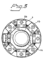
- Fig. 3 is a cross section of the same heater.
- thermoelectric elements 1 of alternately p and n character are arranged in rows and electrically connected in series by means of connector members 2.
- thermoelectric elements 1 which are made of e.g. lead and tellurium and a doping agent have a cylindrical shape and a length approximately corresponding to their diameter.
- Dependent on the intended use and the temperature interval other materials with known thermoelectric character may be chosen.
- said cylindrical elements 1 are not to be mounted standing between connector members but according to the present invention the latter have the shape of a plate on one side of which are made two essentially half-cylindrical parallel seats 3 for thermoelectric elements 1.
- Said plates 2 are intended to be mounted with said seats 3 facing each other on either side of a row of elements 1, opposed plates 2 being mutually off-set one seat width so as to form a continuous winding serial path for the generated current.
- the plates 2 are made planar on their side opposite to the seats 3 or otherwise adapted for lying against an intended hot surface.
- the opposed plates 2 are facing or engaging a suitable cooled surface.
- thermoelectric elements 1 are made similar to each other.
- thermoelectric generator unit As is further evident from Fig. 1, it is suggested according to the invention that two such rows of elements 1 with associated connector plates 2 are located in parallel and electrically connected to each other at one end of said pair of rows such that the two connection conduits to the thermoelectric generator unit will be situated adjacent each other at the opposite end of said pair of rows.
- said pair of element rows is arranged in one trough-like half-part 4a of a surrounding and sealingly closable housing 4.
- This half-part 4a is intended to face or engage with its bottom surface a hot surface such as a combustion tube of a parking heater while the other half-part 4b of the housing is made as a chamber for a suitable cooling fluid such as water.
- the housing 4 is made of stainless steel and in such case it is suitable that the same be welded all around the periferal edge between the half-parts 4a, 4b.
- an isolating layer 8 of mica or a ceramic material Between the rows of elements 1 with the associated connector plates 2 and the upper half-part 4b are arranged in order an electrically isolating layer 5 of plastic such as polyimide, a membrane metal plate 6 preferably of stainless steel and a pressure spring device 7 which here consists of two parallel pressure spring profiles 7a, 7b which are urged against the other half-part 4b of the housing.
- Said other or second half-part 4b of the housing preferably is made, such as is evident from Fig. 1, as a hollow chamber for a suitable cooling fluid such as water.
- a suitable cooling fluid such as water.
- suitable connecting pieces 9a, 9b for a cooling fluid circuitry are also illustrated.
- the electric connecting cables for the cassette-like thermoelectric generator unit suitably are arranged to extend from tubular pieces 10 on one end surface of the lower half-part 4a of the housing together with suitable sealing rings.
- the electric connecting cables for the cassette-like thermoelectric generator unit suitably are arranged to extend from tubular pieces 10 on one end surface of the lower half-part 4a of the housing together with suitable sealing rings.
- At the opposite small-end of said lower half-part 4a of the housing there are preferably mounted two further tubular pieces 11 adapted to provide for a filling of the trough-shaped space within said half-part 4a with a suitable isolating material such as perlite.
- said cavity is to be filled finally with some inert gas, preferably of low-heat conduction capacity or be subjected to vacuum in order to prevent an oxidation of the surfaces between the thermoelectric elements 1 and the connector plates 2, should the thermoelectric material be sensible to oxygene.
- said connector plates 2 preferably are made of copper and coated with nickel and as far as the plates at the cooled side are concerned, also with tin, if desired.
- a particular advantage of the above-stated construction with so-to-speak "lying" cylindrical elements 1 is that the expansion movements which occur when heating them to operating temperature of the unit will imply that the pressure force on the respective elements is increased and hence also the good engagement between the elements and the plates.
- the design according to the invention also provides for manufacturing advantages by allowing an easy maintaining of exact measures of the dimensions of both the element diameter and the connector plates. Furthermore, it is easy to adapt the interface areas to the desired electric effect, burner size etc.
- Figs. 2 and 3 has been illustrated an example of the use of cassette-like thermoelectric generator units according to the invention in a vehicle parking heater.
- Said heater thus comprises in its portion to the right of the drawing a fuel supply device 12 of a kind known per se with an ignition device 13 and a combustion tube 14 in which the combustion essentially takes place. The combustion gases then are discharged to the left of said drawing figure.
- Around the combustion tube 14 are in this case arranged eight cassette-like generator units 4 according to the invention.
- the units are electrically connected as desired and as known per se while the respective second casing halves 4b with their connection pieces are connected to some suitable system for supply of coolant, particularly water.
Landscapes
- Air-Conditioning For Vehicles (AREA)
- Resistance Heating (AREA)
- Instantaneous Water Boilers, Portable Hot-Water Supply Apparatuses, And Control Of Portable Hot-Water Supply Apparatuses (AREA)
Claims (5)
- Unité formant générateur thermoélectrique comportant une pluralité d'éléments (1) thermoélectrique de signes p et n en alternance et connectés électriquement en série au moyen d'éléments (2) connecteurs métalliques, les éléments ayant une forme sensiblement cylindrique et les éléments connecteurs étant formés en tant que plaques (2), caractérisée en ce que sur un côté des éléments connecteurs sont réalises deux sièges (3) sensiblement semi-cylindriques et parallèles pour des éléments (1) thermoélectrique, éléments connecteurs qui sont conçus pour être placés, avec les sièges (3) qui se font face mutuellement, de part et d'autre dune rangée d'éléments (1), avec des plaques opposées mutuellement décalées longitudinalement dune largeur de siège de la rangée de manière à former un trajet en série d'enroulement continu pour le courant produit, les plaques (2) sur un côté de la rangée d'éléments étant conçues pour faire face à une source de chaleur, tandis que les plaques sur le côté opposé font face à un puits de chaleur.
- Unité suivant la revendication 1, caractérisée en ce que pour assurer un contact électrique complet et fiable à l'interface entre les plaques (2) connecteurs et les éléments (1), au moins les surfaces des sièges (3) sur les plaques (2) de cuivre sont revêtues de nickel et, en ce qui concerne les plaques du côté froid, sont en outre recouvertes d'étain.
- Unité suivant la revendication 1 ou 2, caractérisée en ce que les éléments (1) thermoélectriques avec des plaques (2) connecteurs associés sont disposés suivant deux rangées parallèles qui sont connectées mutuellement électriquement à une extrémité des rangées d'éléments tandis que les connexions électriques à un consommateur sont situées à l'extrémité opposée des rangées d'éléments, les rangées d'éléments avec les plaques connecteurs associées étant situées dans une moitié (4a) en forme de tranchée d'un boítier (4) environnant fermé de manière étanche, la moitié de boítier étant conçue pour coopérer avec une surface chaude tandis que l'autre moitié (4b) de boítier est constituée dune chambre pour fluide de refroidissement.
- Unité suivant la revendication 3, caractérisée en ce que le boítier (4) est réalisé en acier inoxydable et est soudé de préférence le long de son bord périphérique entre les moitiés (4a, 4b).
- Unité suivant la revendication 3 ou 4, caractérisée en ce que entre les rangées d'éléments avec des plaques (2) connecteurs associées et l'autre moitié (4b) du boitier (4) se trouvent dans cet ordre, en commençant à partir des rangées d'éléments, une couche (5) isolante vis-à-vis de l'électricité, une feuille (6) métallique en forme de membrane de préférence en acier inoxydable et un dispositif (7) à ressort sous pression qui est pressé contre l'intérieur de l'autre moitié (4b) du boítier.
Applications Claiming Priority (2)
| Application Number | Priority Date | Filing Date | Title |
|---|---|---|---|
| CA002252671A CA2252671A1 (fr) | 1997-02-21 | 1997-02-21 | Convertisseur thermoelectrique |
| PCT/SE1997/000296 WO1998037587A1 (fr) | 1997-02-21 | 1997-02-21 | Convertisseur thermoelectrique |
Publications (2)
| Publication Number | Publication Date |
|---|---|
| EP0907973A1 EP0907973A1 (fr) | 1999-04-14 |
| EP0907973B1 true EP0907973B1 (fr) | 2002-05-08 |
Family
ID=25680615
Family Applications (1)
| Application Number | Title | Priority Date | Filing Date |
|---|---|---|---|
| EP97916684A Expired - Lifetime EP0907973B1 (fr) | 1997-02-21 | 1997-02-21 | Convertisseur thermoelectrique |
Country Status (4)
| Country | Link |
|---|---|
| US (1) | US6034318A (fr) |
| EP (1) | EP0907973B1 (fr) |
| CA (1) | CA2252671A1 (fr) |
| WO (1) | WO1998037587A1 (fr) |
Cited By (1)
| Publication number | Priority date | Publication date | Assignee | Title |
|---|---|---|---|---|
| DE202010003196U1 (de) | 2009-04-21 | 2010-07-29 | TEC COM GmbH Gesellschaft für Technik, Technologie & Vermarktung | Thermoelektrischer Generator (TEG) |
Families Citing this family (19)
| Publication number | Priority date | Publication date | Assignee | Title |
|---|---|---|---|---|
| JP2946205B1 (ja) * | 1997-12-25 | 1999-09-06 | セイコーインスツルメンツ株式会社 | 熱発電ユニット並びに該ユニットを用いた携帯用電子機器 |
| US6312617B1 (en) | 1998-10-13 | 2001-11-06 | Board Of Trustees Operating Michigan State University | Conductive isostructural compounds |
| US6271459B1 (en) * | 2000-04-26 | 2001-08-07 | Wafermasters, Inc. | Heat management in wafer processing equipment using thermoelectric device |
| US6459036B1 (en) | 2000-11-10 | 2002-10-01 | The Boc Group, Inc. | Cascaded inert gas purging of distributed or remote electronic devices through interconnected electrical cabling |
| US6855882B2 (en) * | 2000-11-10 | 2005-02-15 | The Boc Group, Inc. | Cascaded inert gas purging system |
| US6580025B2 (en) | 2001-08-03 | 2003-06-17 | The Boeing Company | Apparatus and methods for thermoelectric heating and cooling |
| US7321591B2 (en) * | 2002-09-24 | 2008-01-22 | Efficient Networks, Inc. | Methods and systems for providing differentiated quality of service in a communications system |
| JP2004350479A (ja) * | 2003-05-26 | 2004-12-09 | Hitachi Powdered Metals Co Ltd | 熱電変換発電ユニットおよびこの熱電変換発電ユニットを備えるトンネル型炉 |
| US8481843B2 (en) * | 2003-09-12 | 2013-07-09 | Board Of Trustees Operating Michigan State University | Silver-containing p-type semiconductor |
| CN100452466C (zh) * | 2003-09-12 | 2009-01-14 | 密歇根州州立大学托管委员会 | 热电材料及其制备方法、热电元件以及从热能生成电流的方法 |
| JP4686171B2 (ja) * | 2004-10-29 | 2011-05-18 | 株式会社東芝 | 熱−電気直接変換装置 |
| EP2171778A1 (fr) * | 2007-06-26 | 2010-04-07 | The Coleman Company, Inc. | Appareil électrique qui utilise plusieurs sources d'alimentation |
| US8519254B2 (en) | 2008-04-08 | 2013-08-27 | The Boeing Company | Device and method for generating electrical power |
| US8230690B1 (en) * | 2008-05-20 | 2012-07-31 | Nader Salessi | Modular LED lamp |
| US10012375B1 (en) | 2008-05-20 | 2018-07-03 | Nader Salessi | Modular LED lamp |
| US9082928B2 (en) | 2010-12-09 | 2015-07-14 | Brian Isaac Ashkenazi | Next generation thermoelectric device designs and methods of using same |
| KR20140029437A (ko) * | 2011-04-19 | 2014-03-10 | 홋카이도 도쿠슈시료우 가부시키가이샤 | 연소장치 및 연소방법과, 그것을 이용한 발전장치 및 발전방법 |
| US20130327369A1 (en) * | 2012-06-07 | 2013-12-12 | Gentherm Incorporated | Thermoelectric system with mechanically compliant element |
| KR102398882B1 (ko) * | 2017-05-30 | 2022-05-18 | 현대자동차주식회사 | 차량용 에어컨시스템의 발전모듈 |
Family Cites Families (9)
| Publication number | Priority date | Publication date | Assignee | Title |
|---|---|---|---|---|
| US3197342A (en) * | 1961-09-26 | 1965-07-27 | Jr Alton Bayne Neild | Arrangement of thermoelectric elements for improved generator efficiency |
| US3481794A (en) * | 1965-03-11 | 1969-12-02 | Westinghouse Electric Corp | Thermoelectric device with plastic strain inducing means |
| FR2519804A1 (fr) * | 1982-01-14 | 1983-07-18 | Accumulateurs Fixes | Boitier pour batterie de generateurs electrochimiques |
| US4855810A (en) * | 1987-06-02 | 1989-08-08 | Gelb Allan S | Thermoelectric heat pump |
| US5015546A (en) * | 1989-06-12 | 1991-05-14 | Grid Systems Corporation | Battery compartment |
| US5228923A (en) * | 1991-12-13 | 1993-07-20 | Implemed, Inc. | Cylindrical thermoelectric cells |
| JP3263855B2 (ja) * | 1992-03-06 | 2002-03-11 | ソニー株式会社 | バッテリーパック |
| US5441576A (en) * | 1993-02-01 | 1995-08-15 | Bierschenk; James L. | Thermoelectric cooler |
| US5817188A (en) * | 1995-10-03 | 1998-10-06 | Melcor Corporation | Fabrication of thermoelectric modules and solder for such fabrication |
-
1997
- 1997-02-21 US US09/142,150 patent/US6034318A/en not_active Expired - Fee Related
- 1997-02-21 EP EP97916684A patent/EP0907973B1/fr not_active Expired - Lifetime
- 1997-02-21 WO PCT/SE1997/000296 patent/WO1998037587A1/fr active IP Right Grant
- 1997-02-21 CA CA002252671A patent/CA2252671A1/fr not_active Abandoned
Cited By (1)
| Publication number | Priority date | Publication date | Assignee | Title |
|---|---|---|---|---|
| DE202010003196U1 (de) | 2009-04-21 | 2010-07-29 | TEC COM GmbH Gesellschaft für Technik, Technologie & Vermarktung | Thermoelektrischer Generator (TEG) |
Also Published As
| Publication number | Publication date |
|---|---|
| EP0907973A1 (fr) | 1999-04-14 |
| CA2252671A1 (fr) | 1998-08-27 |
| US6034318A (en) | 2000-03-07 |
| WO1998037587A1 (fr) | 1998-08-27 |
Similar Documents
| Publication | Publication Date | Title |
|---|---|---|
| EP0907973B1 (fr) | Convertisseur thermoelectrique | |
| US11056735B2 (en) | Heat exchanger and battery unit structure for cooling thermally conductive batteries | |
| US6236810B1 (en) | Fluid temperature control device | |
| US6096966A (en) | Tubular thermoelectric module | |
| CN102369611B (zh) | 热电发电机单元 | |
| JP5785763B2 (ja) | 熱転送装置および製造方法 | |
| US4281516A (en) | Thermoelectric heat exchanger including a liquid flow circuit | |
| KR20070102603A (ko) | 전기 화학적 산소 발생 모듈 어셈블리 | |
| CN102686313B (zh) | 电加热式催化剂 | |
| KR20040083420A (ko) | 열처리로용 전기 히터 | |
| US20150224850A1 (en) | Heater module including thermal energy storage mataerial | |
| US20120251087A1 (en) | Heat storage devices | |
| JPH0143226B2 (fr) | ||
| US5727118A (en) | Electric boiler for heat-transfer liquid circulating in an open or closed circuit | |
| WO2003094249A1 (fr) | Vaporisateurs, generateurs d'electricite et climatiseurs thermoelectriques | |
| CA2613300A1 (fr) | Dispositif de chauffage a dispositif thermoelectrique | |
| US20180226557A1 (en) | Thermoelectric heat exchanger | |
| CN103628955B (zh) | 热传递单元 | |
| CN104919610A (zh) | 热电变换模块 | |
| US7865073B2 (en) | Heating module comprising a heating surface, flow heater, and method for the production thereof | |
| JPH11215867A (ja) | 熱電発電素子構造体及び熱電発電システム | |
| EP1352168A1 (fr) | Element de moteur-fusee et procede de fabrication d'un element de moteur-fusee | |
| JPH0412633Y2 (fr) | ||
| RU2794747C1 (ru) | Универсальная термоэлектрическая приставка | |
| JPH0412634Y2 (fr) |
Legal Events
| Date | Code | Title | Description |
|---|---|---|---|
| PUAI | Public reference made under article 153(3) epc to a published international application that has entered the european phase |
Free format text: ORIGINAL CODE: 0009012 |
|
| 17P | Request for examination filed |
Effective date: 19981005 |
|
| AK | Designated contracting states |
Kind code of ref document: A1 Designated state(s): AT BE CH DE DK FI FR GB IT LI NL SE |
|
| 17Q | First examination report despatched |
Effective date: 20010205 |
|
| GRAG | Despatch of communication of intention to grant |
Free format text: ORIGINAL CODE: EPIDOS AGRA |
|
| GRAG | Despatch of communication of intention to grant |
Free format text: ORIGINAL CODE: EPIDOS AGRA |
|
| GRAH | Despatch of communication of intention to grant a patent |
Free format text: ORIGINAL CODE: EPIDOS IGRA |
|
| REG | Reference to a national code |
Ref country code: GB Ref legal event code: IF02 |
|
| GRAH | Despatch of communication of intention to grant a patent |
Free format text: ORIGINAL CODE: EPIDOS IGRA |
|
| GRAA | (expected) grant |
Free format text: ORIGINAL CODE: 0009210 |
|
| AK | Designated contracting states |
Kind code of ref document: B1 Designated state(s): AT BE CH DE DK FI FR GB IT LI NL SE |
|
| PG25 | Lapsed in a contracting state [announced via postgrant information from national office to epo] |
Ref country code: NL Free format text: LAPSE BECAUSE OF FAILURE TO SUBMIT A TRANSLATION OF THE DESCRIPTION OR TO PAY THE FEE WITHIN THE PRESCRIBED TIME-LIMIT Effective date: 20020508 Ref country code: LI Free format text: LAPSE BECAUSE OF FAILURE TO SUBMIT A TRANSLATION OF THE DESCRIPTION OR TO PAY THE FEE WITHIN THE PRESCRIBED TIME-LIMIT Effective date: 20020508 Ref country code: IT Free format text: LAPSE BECAUSE OF FAILURE TO SUBMIT A TRANSLATION OF THE DESCRIPTION OR TO PAY THE FEE WITHIN THE PRESCRIBED TIME-LIMIT;WARNING: LAPSES OF ITALIAN PATENTS WITH EFFECTIVE DATE BEFORE 2007 MAY HAVE OCCURRED AT ANY TIME BEFORE 2007. THE CORRECT EFFECTIVE DATE MAY BE DIFFERENT FROM THE ONE RECORDED. Effective date: 20020508 Ref country code: FR Free format text: LAPSE BECAUSE OF FAILURE TO SUBMIT A TRANSLATION OF THE DESCRIPTION OR TO PAY THE FEE WITHIN THE PRESCRIBED TIME-LIMIT Effective date: 20020508 Ref country code: FI Free format text: LAPSE BECAUSE OF FAILURE TO SUBMIT A TRANSLATION OF THE DESCRIPTION OR TO PAY THE FEE WITHIN THE PRESCRIBED TIME-LIMIT Effective date: 20020508 Ref country code: CH Free format text: LAPSE BECAUSE OF FAILURE TO SUBMIT A TRANSLATION OF THE DESCRIPTION OR TO PAY THE FEE WITHIN THE PRESCRIBED TIME-LIMIT Effective date: 20020508 Ref country code: BE Free format text: LAPSE BECAUSE OF FAILURE TO SUBMIT A TRANSLATION OF THE DESCRIPTION OR TO PAY THE FEE WITHIN THE PRESCRIBED TIME-LIMIT Effective date: 20020508 Ref country code: AT Free format text: LAPSE BECAUSE OF FAILURE TO SUBMIT A TRANSLATION OF THE DESCRIPTION OR TO PAY THE FEE WITHIN THE PRESCRIBED TIME-LIMIT Effective date: 20020508 |
|
| REF | Corresponds to: |
Ref document number: 217449 Country of ref document: AT Date of ref document: 20020515 Kind code of ref document: T |
|
| REG | Reference to a national code |
Ref country code: CH Ref legal event code: EP |
|
| REF | Corresponds to: |
Ref document number: 69712482 Country of ref document: DE Date of ref document: 20020613 |
|
| PG25 | Lapsed in a contracting state [announced via postgrant information from national office to epo] |
Ref country code: DK Free format text: LAPSE BECAUSE OF FAILURE TO SUBMIT A TRANSLATION OF THE DESCRIPTION OR TO PAY THE FEE WITHIN THE PRESCRIBED TIME-LIMIT Effective date: 20020808 |
|
| NLV1 | Nl: lapsed or annulled due to failure to fulfill the requirements of art. 29p and 29m of the patents act | ||
| REG | Reference to a national code |
Ref country code: CH Ref legal event code: PL |
|
| EN | Fr: translation not filed | ||
| PG25 | Lapsed in a contracting state [announced via postgrant information from national office to epo] |
Ref country code: GB Free format text: LAPSE BECAUSE OF NON-PAYMENT OF DUE FEES Effective date: 20030221 |
|
| PG25 | Lapsed in a contracting state [announced via postgrant information from national office to epo] |
Ref country code: SE Free format text: LAPSE BECAUSE OF NON-PAYMENT OF DUE FEES Effective date: 20030222 |
|
| PLBE | No opposition filed within time limit |
Free format text: ORIGINAL CODE: 0009261 |
|
| STAA | Information on the status of an ep patent application or granted ep patent |
Free format text: STATUS: NO OPPOSITION FILED WITHIN TIME LIMIT |
|
| 26N | No opposition filed |
Effective date: 20030211 |
|
| PG25 | Lapsed in a contracting state [announced via postgrant information from national office to epo] |
Ref country code: DE Free format text: LAPSE BECAUSE OF NON-PAYMENT OF DUE FEES Effective date: 20030902 |
|
| EUG | Se: european patent has lapsed | ||
| GBPC | Gb: european patent ceased through non-payment of renewal fee |