EP0083898A2 - Process and apparatus for continuously casting hollow products employing a magnetic field - Google Patents
Process and apparatus for continuously casting hollow products employing a magnetic field Download PDFInfo
- Publication number
- EP0083898A2 EP0083898A2 EP82420179A EP82420179A EP0083898A2 EP 0083898 A2 EP0083898 A2 EP 0083898A2 EP 82420179 A EP82420179 A EP 82420179A EP 82420179 A EP82420179 A EP 82420179A EP 0083898 A2 EP0083898 A2 EP 0083898A2
- Authority
- EP
- European Patent Office
- Prior art keywords
- mandrel
- rotor
- mold
- rotation
- magnetic material
- Prior art date
- Legal status (The legal status is an assumption and is not a legal conclusion. Google has not performed a legal analysis and makes no representation as to the accuracy of the status listed.)
- Granted
Links
Images


Classifications
-
- B—PERFORMING OPERATIONS; TRANSPORTING
- B22—CASTING; POWDER METALLURGY
- B22D—CASTING OF METALS; CASTING OF OTHER SUBSTANCES BY THE SAME PROCESSES OR DEVICES
- B22D11/00—Continuous casting of metals, i.e. casting in indefinite lengths
- B22D11/10—Supplying or treating molten metal
- B22D11/11—Treating the molten metal
- B22D11/114—Treating the molten metal by using agitating or vibrating means
- B22D11/115—Treating the molten metal by using agitating or vibrating means by using magnetic fields
-
- B—PERFORMING OPERATIONS; TRANSPORTING
- B22—CASTING; POWDER METALLURGY
- B22D—CASTING OF METALS; CASTING OF OTHER SUBSTANCES BY THE SAME PROCESSES OR DEVICES
- B22D11/00—Continuous casting of metals, i.e. casting in indefinite lengths
- B22D11/006—Continuous casting of metals, i.e. casting in indefinite lengths of tubes
Definitions
- the subject of the present invention is a method for manufacturing hollow bodies by continuous casting with the use of a magnetic field which acts on the liquid metal in an annular zone adjacent to an internal mandrel, as well as the device for implementing said method. .
- the method according to the invention can be applied to all metals capable of being continuously cast by the conventional methods of casting solid bodies and among which mention may be made of aluminum, copper and steels.
- the method according to the invention will be applied with particularly great interest to the manufacture of hollow bodies of circular section and, in particular, by operating by rotary continuous casting, the hollow bodies obtained being able, for example, to serve as blanks having good qualities of inner and outer skins for the manufacture of seamless tubes.
- a metallic cylindrical or cylindrical-conical mandrel for example made of copper, is cooled internally with water and disposed co-axially inside the ingot mold or external casting mold. Arrangements are also made to cool the inner wall of the hollow product obtained, generally with water, after the formation of a solidified surface layer. As it is poured, the initially liquid metal solidifies on contact with the mandrel, the solidification front then progressing radially with respect to said mandrel.
- the inner skin of these products therefore has the same types of defects that are observed on the outer skin of solid bodies in conventional castings. These faults are further exacerbated by the limited space available which prevents the introduction of any mechanical device making it possible to eliminate them at least partially.
- the inductors used in this process are supplied by a single-phase alternating current and therefore create a stationary sinusoidal magnetic field, generally qualified as a pulsating field.
- This pulsating field mainly promotes the creation of pressure forces within the liquid metal, which move it away from the fixed walls in which the inductors are contained, without generating significant circulatory movements within the mass of liquid metal.
- Such a technique is probably usable for aluminum, which has a shallow solidification well and a relatively flat solidification front.
- This process has the disadvantage of disturbing heat exchange and delaying the progression of the solidification front from the mandrel.
- it is necessary to carry out a treatment of the internal surface of the product obtained before use to remove, among other things, the layer of slag deposited on the internal skin.
- a device has also been sought for implementing such a simple and economical process, and applicable to the casting of numerous metals or alloys.
- the object of the invention is a method of manufacturing metallic hollow bodies by vertical continuous casting, in which liquid metal is continuously introduced into an annular space comprised between an exterior metallic mold cooled by fluid circulation and an interior mandrel. also cooled by circulation of fluid, this metal gradually solidifying in contact with the walls of the mold and the mandrel with the formation of a hollow body which is extracted below the mold and in which, in an annular zone close to the external surface of the mandrel, the liquid metal is subjected to the action of a mobile magnetic field or sliding field which creates inside this metal forces, having a vertical component directed from bottom to top, which entrain this metal towards the free surface of the metal bath.
- the liquid metal located in the vicinity of the internal mandrel is entrained from bottom to top, in a direction opposite to the direction of extraction of the hollow product formed.
- This upward movement of the liquid metal in this annular zone accelerates the ascent towards the free surface of the metal bath, of inclusions or dross present in the liquid metal in the vicinity of the external surface of the mandrel.
- the radial displacement of the liquid metal eliminates the inclusions or floating slag particles.
- these various inclusions or particles no longer risk being trapped in the inner skin area of the hollow body obtained.
- the liquid metal is, in general, introduced continuously and controlled by a jet coming, for example, from a pouring nozzle which makes it possible to adjust the flow rate and the impact of the jet, both in angle and in position.
- the free surface of the metal bath can either be in contact with the atmosphere or be protected by any known means such as, for example, a protective neutral gas introduced in the liquid or gaseous state, or else a slag.
- the mobile magnetic field which plays an essential role, can be created by any suitable means consisting of inductor systems, fixed or mobile relative to the liquid metal, supplied with polyphase alternating current, or in mobile inductor systems constituted by powered windings by direct current or by a magnetic magnetic material.
- a particularly simple and effective embodiment of the mobile magnetic field consists in using a magnetic rotor constituted by a rotor of revolution on which a magnetized magnetic material is fixed, this magnetic rotor being contained in the mandrel inside, and animated by a rotational movement around its axis thanks to a drive means.
- said magnetic rotor is driven in rotation by the cooling fluid of the internal mandrel via a turbine or any other suitable direct or indirect drive means.
- a magnetic rotor it is arranged to favor the vertical component of the mobile magnetic field with respect to the horizontal component which tends to drive the liquid metal in rotation around the mandrel .
- the speed of rotation adopted for the rotor is such that the mobile magnetic field also called sliding field when one considers essentially its vertical component, has a sufficient frequency to have an effect of ascent of the metal along the notable mandrel, without however that this frequency is too high, the field then being absorbed, for the most part, by the metallic screen aue constitute the mandrel and also the layer of solidified metal along the outer wall of the mandrel.
- Rotational speeds from 1000 to 3000 rpm. corresponding to frequencies from 17 to 50 Hz, are generally adopted; higher or lower speeds may however be advantageous in some cases.
- the internal mandrel will be given the conicity necessary to allow good release of the products.
- Rotary continuous casting which is commonly practiced for the production of solid bodies of circular section, generally comprises a vertical ingot mold animated by a uniform rotational movement about its axis, the cast metal being extracted vertically under the ingot mold by a continuous downward rotation-translation helical movement.
- the molten metal is introduced into the annular space comprised between an outer mold with vertical axis, of circular section, cooled, rotating at a uniform angular speed around this axis and an internal vertical mandrel, the axis of which is, most often, coincident with the axis of the external mold, said mandrel being cooled by internal circulation of fluid and rotating on itself around its axis, in the same direction as the outer mold, the hollow shaped blank being extracted vertically by a downward helical movement, by extraction means.
- the liquid metal is subjected to a mobile magnetic field having its source inside the mandrel, so as to create forces such as to impart to the liquid metal a movement having a vertical component, D parallel to the axis of the mandrel, directed from the bottom up.
- the angular speed of the internal mandrel is generally substantially equal to that of the external mold, this movement being either controlled by a mechanical device, or the result of the friction drive of the hollow product being solidified on the mandrel.
- the hollow product in the course of solidification is subjected, along and close to the internal mandrel, not only in the vicinity of the surface, but over a height corresponding substantially to the entire height of the external mold, to the mobile magnetic field.
- directions of rotation are adopted such that the rotation of the liquid metal due to the horizontal component of the mobile magnetic field and the rotational movement of the external mold and of the mandrel are in opposite directions.
- the effect of the metal rising along the mandrel is then most marked despite the generally concave shape of the meniscus due to the rotation of the outer mold and the mandrel.
- the rotational speed of the outer mold is generally between 30 and 120 rpm.
- the invention also relates to a device for implementing the method described above.
- This device comprises a vertical exterior mold with a metallic interior wall cooled by internal circulation of fluid, an interior mandrel with metallic wall cooled by circulation of fluid, means of introduction of a liquid metal at the upper part of the annular space between the mandrel and the mold, means for extracting the hollow body downwards during solidification and means for creating a mobile magnetic field housed at inside the chuck.
- the mobile magnetic field can be created by inductive windings, supplied with polyphase current, fixed or mobile relative to the outer wall of the mandrel.
- the mobile magnetic field is created by means of an inductor system rotating relative to the external wall of the mandrel and comprising either windings supplied with direct current, or a magnetic material permanently magnetized.
- the device which is the subject of the invention further comprises means for driving the external mold in rotation as well as extraction means making it possible to extract vertically downwards, with a movement helical, the hollow body in the process of solidification.
- the inner mandrel is preferably arranged coaxially with the mold.
- the rotation of the rotor is ensured by the fluid of the cooling circuit via a turbine located inside the internal mandrel.
- the inner mandrel is imperatively made of a non-magnetic material advantageously having good heat conductivity and as low an electrical conductivity as possible.
- the internal part of the mandrel that is to say the part corresponding to the magnetic rotor, advantageously extends over a height substantially equal to that of the external mold, the rotor projecting above the free level of the metal bath.
- a preferred solution for creating the mobile magnetic field consists in using permanent magnets as magnetized magnetic material, in the form of parallelepipeds with rectangular faces, on the periphery of a rotor made up of a part of revolution made of magnetic material, according to a propeller having a north magnetization homogeneous south, preferably radial.
- the magnetized magnetic material is placed along two offset helices wound around the rotor like a screw. with two threads, each propeller having, in this case, a homogeneous radial magnetization, one of the propellers being magnetized so that at each point a north pole, is closer to the axis of the rotor, and the other propeller So that a south pole is closest to the axis of the rotor at each point
- a mobile polyphase magnetic field is obtained by means of permanent magnets, which is simpler to produce than by using a plurality of polyspire inductors offset in space and which would have to be supplied by polyphase currents.
- the magnetic material being magnetized by centrifugal force, it is important to secure it with the rotor by means of a hoop made of a material based on natural or synthetic fibers covering the material.
- magnetic magnetized and surrounding the magnetic rotor The connection between the hoop and the substrate is preferably ensured by a polymerized synthetic resin which impregnates the hoop.
- the magnetic material which constitutes the rotor is preferably a mild steel or a carbon steel such as a structural steel.
- the intervals between the successive turns of the propeller or propellers made of magnetized magnetic material are preferably filled with a filling material such as a polymerizable mastic reinforced with fiberglass.
- a felt made of non-woven fibrous material.
- fibers with high mechanical characteristics such as glass fibers or polyamides, are used to form the hoop.
- the connection between the felt and the hoop and the substrate is preferably ensured by a polymerized synthetic resin which impregnates both the hoop and the felt.
- a magnetic rubber for example in the form of ribbons or a cobalt-based alloy containing at least one rare earth metal, such as for example samarium, can be used as magnetized magnetic material.
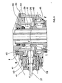
- FIG. 1 The device according to the invention, described here in the case of rotary continuous casting for obtaining hollow steel bars, is shown as a whole in FIG. 1, which has been cut in its lower part to facilitate representation.
- the device for the continuous rotary casting of solid steel bodies, of circular section is known per se, in particular from the publications whose references have been given above.
- FIG. 1 represents a device for rotary continuous casting of hollow bodies according to the invention, which comprises an external mold (1), or ingot mold, rotating about a vertical axis of tubular general shape and of circular section, cooled, an internal mandrel (2), a liquid metal supply system shown diagrammatically by the arrow (3) and a vertical helical extraction system for the cast products.
- the mold (1) or external mold is simply represented by its wall (4) limited by (5) and (6). This wall generally has a slight taper, with a reduction in section in the lower part, which ensures contact with the metal being solidified.
- Its cooling system and its rotary drive means known to those skilled in the art, have not been shown.
- the free surface of the metal is in (7) and the hollow body of circular section, partially solidified is in (8).
- the hollow inner mandrel (2) consists of two parts: the lower part, located at the level of the mold (1) immersed in the metal being solidified, which constitutes the active part of the mandrel, and the upper part, located at top of mold (1), bearing the control and support mechanisms of the lower part.
- the mandrel comprises a sleeve (9), of generally tubular shape, of circular section and of height-slightly greater than the height of the mold (1).
- the sleeve (9) advantageously has a taper with narrowing of the section downwards to allow the removal of the metal during solidification.
- the sleeve (9) is generally made of a non-magnetic material having good heat conductivity, for example, copper or copper alloy.
- the mandrel (2) is held in position in the mold by support means shown in Figure 2, so that the sleeve (9) is perfectly coaxial with the mold (1).
- the sleeve (9) is assembled, for example, by sleeving at (10) with a static seal (11) with a revolution support tube (12) which constitutes the upper part of the mandrel and the upper end of which penetrates in the mandrel head (13).
- a double lip seal (14) allows the free rotation of the mandrel relative to the head (13) while guaranteeing the tightness with respect to the pressurized fluid which circulates inside.
- the rotation of the sleeve (9) is controlled by a motor system shown in Figure 3, which ensures both the mechanization in rotation of the mandrel (2) and its general maintenance in vertical position and centered relative to the mold (1), the axis of the mandrel being coincident with that of the mold (1).
- This mechanical drive device is described below.
- the tube (17) is sealed in its lower part (19); it is secured to the support tube ⁇ (12) by means of radial plates (20-21), which do not obstruct the axial flow between (12) and (17) of the cooling fluid.
- the sleeve (9) and the tube (17) are tightly joined to the lower part by the annular bottom piece (22) with O-ring seals (23) and (24).
- the tube (17) is centered by an annular part (25) relative to which it is free to rotate thanks to a static O-ring (27) inside the head of the mandrel (13).
- a nut (28) screwed at (29) on the tube (17) ensures the blocking of the. bottom piece (22).
- the sleeve (9), the support (12), the tube (17) and the bottom piece (22) are perfectly integral and can rotate at the same speed of rotation.
- the magnetic rotor (18) consists of a free hollow cylinder rotating on the tube (17) and carries on its outer surface a magnetic material. Its particular structure will be described later.
- the length of the rotor is chosen so that its upper part clearly exceeds the level corresponding to the free surface of the liquid metal in the vicinity of the sleeve (9). It is arranged, in construction, so that the interval between rotor (18) and sleeve (9) is as small as possible, taking into account the need to keep a passage section sufficient for the coolant.
- the speed of the rotor (18) is not linked to the speed of the tube (17) and said rotor rotates on rings made of a suitable material, for example of resin-based material plus cereal fiber, (31) and (32 ) positioned on the tube (17).
- the rotor (18), the rotational speed of which must be high, of the order of 1000 to 3000 rpm, is rotated by the cooling fluid via a turbine (33) machined in the lower part of the rotor, and therefore integral with it.
- Figure 2 gives, in section, the profile of the turbine.
- the cooling fluid which is under a suitable pressure inside the tube (17), leaves it by radial holes such as (34) distributed in suitable number at the periphery of the tube (17).
- a set of orifices, such as (35), of suitable profile, are distributed around the periphery of the rotor (18) and oriented so as to cause the rotor drive to react.
- the cooling fluid generally water
- entering at (15), descending inside the tube (17) and rising in the interval (30) to exit at (16) ensures both the cooling of the sleeve (9), to allow the elimination of calories from the metal bath, and the cooling of the rotor and of the magnetized magnetic material.
- a suitable drawing of the parts allows, with a water pressure of 2 to 3 kg / cm 2 to reach a speed of approximately 3000 rpm, keeping the temperature of the magnetic rotor as a whole below 100 ° C, the circulation speeds adopted making it possible to avoid the presence of air in the cooling circuit.
- the rotational speed of the rotor that which allows a sufficiently high upward displacement speed of the liquid metal to be obtained.
- the ratio between the upward movement speed of the liquid metal and the speed of rotation of the rotor is a function of this speed of rotation. Beyond a critical speed of rotation, the speed of upward movement of the liquid metal no longer increases and, on the contrary, begins to decrease rapidly.
- This critical speed of rotation depends in particular on the nature of the material which constitutes the wall of the sleeve (9) and on the thickness of the latter.
- This mechanism essentially consists of a toothed crown (36) hooped on the part (12) moved by a drive shaft (37), at the end of which there is a bevel gear (38).
- the crown is supported in its rotation by two conical roller boxes (39) and (40), which keep the mandrel (2) in a fixed vertical position.
- the shaft (37) also rotates in a box with two conical rollers (41) and (42), a sealed and cooled casing (43-44) closing the whole.
- Seals (45-46) provide sealing during rotation of the mandrel.
- the head of the mandrel (13) is fixed to the motor shaft housing by the lugs (P) and (47) and the bolts (48).
- the mandrel (2) is positioned on the mold (1) by a non-figured system, of legs moored on the one hand, on the work floor which may be at the height of the mold (1), and on the other hand, on the casing (43-44) or on the head (13) of the mandrel. Thus, it maintains a well defined vertical position of the mandrel.
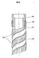
- the structure of the magnetic rotor (18), creating the mobile field is shown in elevation, Figure 4, the upper part of the figure being in section.
- This rotor consists of a hollow cylinder (49) of structural steel, the ends of which are profiled to allow the accommodation of the friction rings (31-32) allowing to center in rotation with a minimum of friction said rotor.
- the magnetized magnetic material consists of permanent magnets such as (50) positioned in housings such as (51), made side by side in a helix, on the surface of the cylinder. These magnets are fixed in their housing, for example by gluing. Is advantageously used cuboid magnets to face s rectangle, whose long sides are oriented parallel to the generatrices, the north-south axis perpendicular to the large faces, corresponding to the smallest distance between faces of the parallelepiped, and being radial, that is to say perpendicular to the axis of the rotor.
- the propellers are two in number, coaxial (52) and (53), arranged around the rotor in the manner of a double thread with a pitch to the right, each propeller being magnetically oriented so homogeneous, that is to say that the poles closest to the axis of the rotor of all the magnets of the same propeller are of the same name.
- the magnetic orientation of the two propellers is opposite.
- the poles of the propeller (52), closest to the axis of the rotor are south, while those of the propeller (53) closest to the axis of the rotor, are north.
- Any permanent magnet that is sufficiently stable can be used.
- the direction of winding of the propeller or propellers on the magnetic rotor must be the same as the direction of rotation of the rotor around its axis seen from above. Thus, if the rotor seen from above turns clockwise, the propeller or propellers must have a right pitch.
- This rotor structure creates by rotation, a mobile magnetic field also called sliding field whose direction of movement is at each point perpendicular to the threads of the propeller and contained in the plane tangent to the surface of the cylinder.
- the direction of movement of this sliding field therefore has, on the one hand, a vertical component which drives the liquid metal from bottom to top, on the other hand a horizontal component which will tend to drive the liquid metal in rotation.
- the pitch of the propeller or propellers is chosen so that the horizontal component of the magnetic field remains weak, while not bringing the poles of opposite names too close on the same generator of the rotor, so as to have field lines penetrating deep into the liquid metal.
- the distance on the same generator, between the ends closest to a north magnet and a south magnet, is preferably not taken less than the great length of the basic parallelepiped.
- the quality of the results obtained in the process according to the invention depends in particular, as will be seen below, on obtaining a sufficiently high speed of upward movement of the liquid metal along the sleeve. It is in fact this upward movement which causes dross and inclusions up to the free surface of the metal and which creates an annular relief around the sleeve which prevents dross floating on the surface of the metal bath from depositing on the interior surface. of the hollow body being solidified.
- the rotor is housed inside a mandrel of relatively large length, which is secured, by only one of its ends, to a fixing means.
- a relatively light magnetic rotor has been developed in the context of the present invention capable of rotating at high speed without the risk of the magnetized magnetic material being torn off.
- This magnetic rotor comprises a part of revolution made of magnetic material, capable of rotating around its axis, on the surface of which is arranged, along at least one helix, a magnetized magnetic material; this magnetized magnetic material is secured to the rotor by at least one hoop consisting of a material based on natural or synthetic fibers as well as by a synthetic resin, this hoop covering the magnetized magnetic material and surrounding the rotor.
- FIG. 5 represents a first embodiment of this magnetic rotor.
- This rotor comprises a magnetic metal part of revolution, consisting of a carbon steel cylinder (64) such as steel type XC 35 (AFNOR standard).
- This cylinder has at each of its two ends a housing (65- 66) intended to receive a friction ring or a ball bearing allowing it to rotate at high speed around its axis with the minimum of friction.
- a turbine machined in the lower part of the rotor, has orifices represented schematically at (67-68), oriented and dimensioned in such a way that the fluid which passes through them, as described above, causes the drive in rotor rotation at the desired speed.
- two parallel helical grooves (69-70) are machined.
- These grooves have a relatively shallow depth (e) and a large width (1 1 ).
- the distance (1 2 ) between two successive grooves is preferably close to (1 1 ).
- the magnetic material is partially engaged in these grooves.
- a magnetic rubber ribbon is used, the active material of which is most often a ferrite which is glued by a suitable means into the groove.
- several thicknesses of magnetic rubber are preferably glued.
- two magnetic helices are produced (71-72), each consisting of three layers of magnetic rubber (711-712-713) and (7 2 1 - 72 2 -72 3 ).
- the North-South magnetization axis is radial and in the same direction all along the propeller.
- the direction of magnetization changes from one propeller to another.
- the propeller (71) has on the outside a North pole (N) and the propeller (72), on the contrary, a South pole (S).
- the gap (73) between the helices is filled with a filling and bonding material such as a mixture of fibrous material and a resin. polymerizable with good wetting power with respect to the surface of the steel cylinder and also with regard to magnetic material. To improve adhesion, knurling can be carried out on the surface of the cylinder. After hardening of the resin, this bonding material makes it possible, in particular, to avoid any displacement of the magnetic helices relative to one another.
- a filling and bonding material such as a mixture of fibrous material and a resin. polymerizable with good wetting power with respect to the surface of the steel cylinder and also with regard to magnetic material.
- knurling can be carried out on the surface of the cylinder. After hardening of the resin, this bonding material makes it possible, in particular, to avoid any displacement of the magnetic helices relative to one another.
- the hooping of the magnetic material and the filling material on the carbon steel cylinder is carried out by means of a hoop (74) comprising a fabric based on fibers with high modulus of elasticity which completely covers the cylindrical surface formed by the two magnetic propellers and the filling material.
- This hoop (74) is shown in partial section in FIG. 5.
- a layer may be placed between the two. thin, not shown in FIG. 5, of a nonwoven felt based on glass fiber, the assembly then being impregnated with a liquid synthetic resin, which, after polymerization, ensures an excellent bond between the hoop, the felt and the substrate, i.e. the steel cylinder surrounded by magnetic helices and
- the thickness of the hoop is calculated so as to keep the magnetic propellers pressed against the cylinder despite the centrifugal force which is exerted on the magnetic material when the rotor turns at its speed of speed.
- the fibers with high mechanical characteristics which make it possible to produce the hoop, it is possible in particular to use glass fibers, polyamide fibers, or even carbon or boron fibers.
- fibers with a high modulus of elasticity are used.
- Certain natural fibers may also be suitable.
- the relative dimensions of the various elements constituting the magnetic rotor are chosen by a person skilled in the art as a function of the various parameters of the installation for continuous casting of hollow bodies which it is a question of producing and may vary within wide limits. It is thus possible to use for the continuous casting of hollow steel bodies an internal copper mandrel, in which is housed a magnetic rotor with an external diameter of 144 mm and a height of 600 mm. This rotor is driven in rotation about its axis at a speed of the order of 3000 rpm. by a turbine, as described above. This rotor has a cylindrical core of structural steel, 87 mm in diameter and 600 mm high.
- each of these grooves is housed three superimposed layers of a magnetic rubber band of about 9 mm thick and whose width corresponds to that of the groove.
- These ribbons are glued to the back of the throat and also glued together.
- the gap between the ribbons is filled with a polymerizable putty reinforced with fiberglass.
- the whole is then enveloped by a mined layer of about 1 mm thick with a glass felt itself covered with a fabric made of polyamide fibers with high mechanical resistance and high elastic modulus, of about 2 mm thickness which constitutes the hoop.
- the hoop and the felt are impregnated with a polymerizable liquid resin which, after hardening, ensures the connection between the hoop, the felt, and the substrate.
- the thickness of the hoop and that of the felt are adjusted so that the outside diameter of the magnetic rotor reaches approximately 144 mm. Thanks to this hoop, the magnetic tape forms a block with the rotor core and supports without displacement the centrifugal forces resulting from the rotation at 3000 rpm. of the magnetic rotor.
- the clearance between the outer surface of the magnetic rotor and the inner surface of the mandrel in which it is housed must be as small as possible, taking into account the need to leave sufficient passage for the circulation of the cooling fluid, most often of the water.
- the flow rate of this fluid must be determined taking into account not only the calories to be removed but also the need to drive the turbine at the desired speed.
- This distance also called air gap
- This distance corresponds to the sum of 3 terms: the thickness of metal solidified in contact with the external surface of the wall of the mandrel, the thickness of this wall of the mandrel and the distance between the internal surface of this wall of the mandrel and the outer surface of the magnetic propellers.
- a much stronger magnetic field than that which can be obtained by means of magnetic rubber.
- magnets based on cobalt-rare earths such as CORAMAG magnets (registered trademark of AIMANTS UGIMAG SA). These magnets, thanks to their very large coercive field of induction, of approximately 8000 Oe and their very high residual education of the order of 8300 G, make it possible to multiply by a factor of 4, at equal volume, the magnetic field produced.
- FIG. 6 represents in partial section a magnetic rotor comprising such magnets.
- a rotor which consists of a carbon steel cylinder (75), of the same design as the cylinder (64) of FIG. 5.
- the lower part of the cylinder which includes the drive turbine similar to that schematically described in Figure 5, is not shown.
- This rotor comprises, like that of FIG. 5, two parallel helical grooves (76) and (77), of shallow depth and relatively large width in which are housed parallel-pipedic plates of cobalt-rare earth magnetic alloy such as those sold under the CORAMAG brand.
- These alloys are based on cobalt and contain rare earths such as the samarium combined with cobalt at least partly in the form of intermetallic comnoses such as TR Co 5 or TR2Co17, TR being a rare earth metal.
- the propeller (81) comprises plates whose North pole (N) is on the side furthest from the axis of the rotor, while, for the propeller (82), c 'is on the contrary the South pole (S) which is furthest from the axis of the rotor.
- N North pole
- S South pole
- a filling and bonding material such as a polymerizable putty reinforced with glass fiber which fills the gap between the turns, and then it is arranged around the together a hoop (88) constituted by a layer of fabric based on fibers with high mechanical characteristics and, in particular, with high modulus of elasticity, which completely covers the cylinder.
- This hoop can, for example, be constituted by a ribbon wound helically around the cylinder or else have the shape of a sleeve which is threaded around the cylinder.
- a fabric based on glass fibers can be used for this.
- the hoop (88) is shown only partially in the area in axial section. It obviously covers the entire cylindrical surface of the rotor so as to strongly tighten the magnetic plates and keep them firmly in contact with the bottom of the grooves (76) and (77), even when the rotor is rotated at 3000 rpm. or more.
- the hoop (88) is preferably secured to the substrate by impregnating this hoop with a polymerizable liquid resin of known type.
- a nonwoven felt based on glass fibers can be placed between the two, for example, which makes it possible to achieve elastic tightening at all points.
- the connection between the fret, the felt and the underlying materials is preferably produced by impregnation using liquid polymerizable resin.
- magnetized magnetic material Numerous types of magnets can be used as magnetized magnetic material, the magnetic or dimensional characteristics of which can be extremely varied.
- the rotational drive of the magnetic rotor can be achieved by many different means. We can, in particular, perform this drive, not by means of a turbine driven by the coolant, but by means of an electric motor, which can be connected directly to the rotor, or, on the contrary, be connected to the latter by a mechanical drive means of suitable length.
- the hoop can also be produced in a large number of different ways using a very wide variety of synthetic or even natural fibers.
- the continuous casting device according to the invention can be further improved by planning to place, as shown in FIG. 1, under the rotary mandrel, a screen (54), the function of which is to reduce the radiation from the internal surface of the hollow bar, once out of the mandrel.
- a screen constituted by a hollow metal cylinder with a solid bottom, can be fixed by screwing at (55) on an extension of the central tube (17).
- This protective gas is brought to the head (13) at (60). In this way, the cooling water cannot escape from the mandrel (2) and there is no risk of untimely penetration of the water into the interior cavity of the bars being solidified.
- a seal (61) prevents the penetration of cooling water from the tube (17).
- a lubrication device using vegetable oil, rapeseed oil type can be provided in the sleeve (9) -metal skin interface during solidification, for example, by a drip dispenser.
- the device which has just been described, with regard to the magnetic rotor, has the advantage of being particularly simple and compact.
- the device described is its simplicity of implementation. Indeed, to the same support tube (12), it is possible to adapt different dimensions of sleeves (9) including the working diameter, that is to say the diameter of the part immersed in the metal being solidified, corresponding to the different internal diameters of the hollow bodies to be manufactured.
- the sleeve (9) instead of having the shape of a cylinder of revolution of constant section, as in FIG. 1, has over its entire part which is in contact with the cast metal, a shape of revolution corresponding to the inner section of the hollow bar to be manufactured and, in its upper zone, a section corresponding to the sleeve (10) of the support tube (12), the two parts of said sleeve (9) being connected, in this case, by a shoulder.
- the diameter of the rotor (18) is adapted to the inside diameter of the sleeve (9).
- the same rotor can be used for several dimensions of sleeves' (9), therefore of hollow bars.
- the disassembly of the assembly takes place very easily by unscrewing the nut (28), disengaging the bottom piece (22) and disengaging the sleeve (9), the rotor (18) then coming from itself and the tube (17) remaining integral with the support tube (12).
- the liquid metal is fed continuously through (3) into the mold (1), which is rotated at a constant speed.
- the internal mandrel (2) is also driven by a rotation movement at a constant speed substantially equal to that of the mold (1) and in the same direction.
- This rotation of the mandrel is ensured either by the mechanism described in FIG. 3, or simply by the friction of the metal being solidified on the internal mandrel, the mechanism described in FIG. 3 only serving in this case to keep it in the vertical position and centered the rotating mandrel. Due to the continuous mold rotation (1) and the mandrel (2), any localized overheating of the mold and the mandrel, in particular, is avoided by radiation at the place where the liquid metal is introduced by (3) into the mold. .
- the free metal surface (7) which may optionally be protected by a protective gas flow supplied to the gaseous state or li q ui- of, takes, due to the rotation of the mold, the concave general shape as seen in Figure 1, the outer edges rising in (62).
- a protective gas flow supplied to the gaseous state or li q ui- of takes, due to the rotation of the mold, the concave general shape as seen in Figure 1, the outer edges rising in (62).
- inclusions, dross or any non-metallic particles floating on the surface of the metal tend to move away from the periphery.
- the result is a particularly neat exterior surface that does not require surface preparation before further processing. This is well known and exposed, inter alia, in the article of the "Revue de Métallurgie-CIT", already quoted.
- the vertical component of the mobile magnetic field created by the rotating rotor (18) has the effect of totally modifying the normal solidification conditions in the vicinity of the outer surface of the sleeve (9).
- the ascending current of liquid metal which occurs along this sleeve, causes all the dross and inclusions that may be present, rapidly to the free surface of the metal, and, moreover, this current, which is then deflected radially towards the periphery, causes the level of the liquid metal to rise in the vicinity of the mandrel (2), the annular relief (63) thus formed preventing dross floating on the free surface of the metal bath (7) from being deposited on the inner surface of the hollow body being solidified.
- This mechanical barrier effect is added to the effect of entrainment by the surface current which keeps dross away from the mandrel, being on the bath.
- the liquid metal distribution jet is oriented in such a way that it keeps the updrafts and convection currents, in the vicinity of the mandrel, their maximum efficiency.
- the jet (3) is preferably oriented so that the movement of the metal poured into the mold has a radial centrifugal component, the tangential component, which tends to rotate the bath, being directed in the direction of rotation of the mold (1).
- the stirring carried out on the liquid metal being solidified, in the vicinity of the mandrel has the effect of refining the structure of the inner skin of the hollow body obtained.
- the process of rotary continuous casting of hollow bodies applies particularly well to the case of steel.
- the example which has just been given relates to the application of the method according to the invention, to rotary continuous casting, that is to say in the case where the cast hollow body is driven in rotation thus as the mold, the method according to the invention also applies more generally to the processes in which the mold is fixed.
- inductors comprising, for example, windings supplied with three-phase current is known for pumping liquid metals such as sodium and even aluminum.
- Their structure corresponds substantially to that of a portion of a polyphase alternating current motor stator whose curvature is canceled so as to obtain a sliding magnetic field whose translational movement is linear.
- an inductor constituted by a cylinder with a vertical axis made of magnetic material may be housed inside the mandrel, in place of a rotor, having notches protruding in its cylindrical outer wall. which are arranged in series of coils supplied with polyphase alternating current.
- the field translation speed "V" is equal to the product of the pitch of the winding "1” by the frequency "f” of the alternating current.
- the coils are connected to the three-phase current source so that the vertical sliding of the field occurs from bottom to top.
- the translation speed is adjusted by acting on the one hand on the winding pitch and on the other hand, possibly, on the frequency of the polyphase current used.
- the cylinder is fixed so as to vertically entrain the liquid metal in the region adjacent to the mandrel.
- the mobile magnetic field does not have a horizontal component tending to drive the liquid metal in rotation.
- the inductor preferably accompanies the mandrel in its rotational movement.
Landscapes
- Engineering & Computer Science (AREA)
- Mechanical Engineering (AREA)
- Continuous Casting (AREA)
Abstract
Le procedé et le dispositif suivant l'invention concernent la coulée continue de corps creux en métaux tels que l'aluminium, le cuivre, les aciers de tous types, ou autres métaux ou alliages. Le procédé consiste à introduire le métal liquide dans un espace annulaire compris entre un moule extérieur et un mandrin intérieur, le métal liquide étant soumis au voisinage du mandrin à l'action d'un champ magnétique mobile qui l'entraîne vers le haut. Ce champ est, de préférence, créé par un rotor magnétique logé dans le mandrin. Dans un mode de réalisation préférentiel, ce rotor comporte une matière magnétique aimantée maintenue en place par une frette. Le procédé s'applique, en particulier, à la réalisation d'ébauches destinées à la fabrication de tubes sans soudure.The method and the device according to the invention relate to the continuous casting of hollow bodies of metals such as aluminum, copper, steels of all types, or other metals or alloys. The method consists in introducing the liquid metal into an annular space between an external mold and an internal mandrel, the liquid metal being subjected in the vicinity of the mandrel to the action of a mobile magnetic field which drives it upwards. This field is preferably created by a magnetic rotor housed in the mandrel. In a preferred embodiment, this rotor comprises a magnetic magnetic material held in place by a hoop. The method applies, in particular, to the production of blanks intended for the manufacture of seamless tubes.
Description
La présente invention a pour objet un procédé de fabrication de corps creux par coulée continue avec utilisation d'un champ magnétique qui agit sur le métal liquide dans une zone annulaire voisine d'un mandrin intérieur, ainsi que le dispositif de mise en oeuvre dudit procédé.The subject of the present invention is a method for manufacturing hollow bodies by continuous casting with the use of a magnetic field which acts on the liquid metal in an annular zone adjacent to an internal mandrel, as well as the device for implementing said method. .
Le procédé suivant l'invention peut s'appliquer à tous les métaux susceptibles d'être coulés en continu par les méthodes classiques de coulée de corps pleins et parmi lesquels on peut citer l'aluminium, le cuivre et les aciers.The method according to the invention can be applied to all metals capable of being continuously cast by the conventional methods of casting solid bodies and among which mention may be made of aluminum, copper and steels.
Bien qu'il puisse être appliqué, d'une façon tout à fait générale, à la fabrication de corps creux présentant des sections de formes très diverses, le procédé suivant l'invention sera appliqué avec un intérêt particulièrement grand à la fabrication de corps creux de section circulaire et, en particulier, en opérant par coulée continue rotative, les corps creux obtenus pouvant, par exemple, servir d'ébauches présentant de bonnes qualités de peaux intérieure et extérieure pour la fabrication de tubes sans soudure.Although it can be applied, in a very general manner, to the manufacture of hollow bodies having sections of very different shapes, the method according to the invention will be applied with particularly great interest to the manufacture of hollow bodies of circular section and, in particular, by operating by rotary continuous casting, the hollow bodies obtained being able, for example, to serve as blanks having good qualities of inner and outer skins for the manufacture of seamless tubes.
La fabrication de corps creux de section circulaire, c'est-à-dire, présentant un creux intérieur généralement concentrique à la section extérieure, a fait l'objet de nombreuses et diverses descriptions techniques.The manufacture of hollow bodies of circular section, that is to say, having an internal hollow generally concentric with the external section, has been the subject of numerous and various technical descriptions.
D'une façon générale, on utilise dans ces procédés connus un mandrin cylindrique ou cylindro-conique métallique, par exemple en cuivre, refroidi intérieurement à l'eau et disposé co-axialement à l'intérieur de la lingotière ou moule extérieur de coulée. On s'arrange également pour refroidir la paroi intérieure du produit creux obtenu, généralement à l'eau, après formation d'une couche superficielle solidifiée. Au fur et à mesure de la coulée, le métal initialement liquide se solidifie au contact du mandrin, le front de solidification progressant ensuite radialement par rapport audit mandrin. Cette solidification commençant dès la surface libre du bain métallique, il en résulte un emprisonnement dans la couche superficielle solidifiée, qui constitue la peau intérieure du corps creux obtenu, de toutes les crasses constituées de laitiers, inclusions Qu'autres particules non métalliques, présentes à la surface du bain et, d'une façon générale, une peau intérieure présentant des défauts, types incrustations, laitiers, repliures, qui devront être éliminés au moyen de traitements de surface difficiles et coûteux avant utilisation ultérieure du corps creux obtenu.In general, in these known methods, a metallic cylindrical or cylindrical-conical mandrel, for example made of copper, is cooled internally with water and disposed co-axially inside the ingot mold or external casting mold. Arrangements are also made to cool the inner wall of the hollow product obtained, generally with water, after the formation of a solidified surface layer. As it is poured, the initially liquid metal solidifies on contact with the mandrel, the solidification front then progressing radially with respect to said mandrel. This solidification starting from the free surface of the metal bath, it results in an imprisonment in the solidified surface layer, which constitutes the inner skin of the hollow body obtained, of all the dross made up of slag, inclusions than other non-metallic particles, present at the surface of the bath and, in general, an inner skin having defects, such as incrustations, slag, folds, which must be removed by means of difficult and costly surface treatments before subsequent use of the hollow body obtained.
La peau intérieure de ces produits présente donc les mêmes types de défauts qu'on observe sur la peau extérieure des corps pleins dans les coulées classiques. Ces défauts sont encore aggravés par l'exi- guité de l'espace disponible qui empêche l'introduétion de tout dispositif mécanique permettant de les éliminer au moins partiellement.The inner skin of these products therefore has the same types of defects that are observed on the outer skin of solid bodies in conventional castings. These faults are further exacerbated by the limited space available which prevents the introduction of any mechanical device making it possible to eliminate them at least partially.
Certains procédés ont été développés pour essayer de résoudre ces difficultés. Tel est le cas de celui décrit dans le brevet suisse n°618.363 du 6/01/1977, qui utilise l'effet électromagnétique d'un inducteur monospire extérieur et d'un inducteur monospire intérieur pour réaliser la coulée continue de corps creux sans utilisation de lingotière extérieure ou de mandrin.Certain methods have been developed to try to solve these difficulties. This is the case of that described in Swiss Patent No. 618,363 of 6/01/1977, which uses the electromagnetic effect of an external single-coil inductor and an internal single-coil inductor to achieve continuous casting of hollow bodies without use external mold or mandrel.
Les inducteurs utilisés dans ce procédé sont alimentés par un courant alternatif monophasé et créent donc un champ magnétique sinu- soidal stationnaire, généralement qualifié de champ pulsant.The inductors used in this process are supplied by a single-phase alternating current and therefore create a stationary sinusoidal magnetic field, generally qualified as a pulsating field.
Ce champ pulsant favorise principalement la création de forces de pression, au sein du métal liquide, qui l'écartent des parois fixes dans lesquelles sont contenus les inducteurs, sans engendrer au sein de la masse de métal liquide des mouvements circulatoires importants.This pulsating field mainly promotes the creation of pressure forces within the liquid metal, which move it away from the fixed walls in which the inductors are contained, without generating significant circulatory movements within the mass of liquid metal.
Ainsi, selon cette technique, on maintient en équilibre une couronne de métal liquide par un champ magnétique, la surface libre de ce métal ayant une forme convexe, comme le montre la figure 1 du brevet cité.Thus, according to this technique, a ring of liquid metal is kept in equilibrium by a magnetic field, the free surface of this metal having a convex shape, as shown in FIG. 1 of the cited patent.
Etant donné le faible rayon d'action du champ magnétique, cela impose que la colonne de métal liquide soit de hauteur réduite.Given the small radius of action of the magnetic field, this requires that the liquid metal column be of reduced height.
Une telle technique est probablement utilisable pour l'aluminium, qui présente un puits de solidification peu profond et un front de solidification relativement plat.Such a technique is probably usable for aluminum, which has a shallow solidification well and a relatively flat solidification front.
Par contre, dans le cas de l'acier, métal de forte densité (du moins par rapport à l'aluminium), et beaucoup moins conducteur de la chaleur que l'aluminium, le puits de solidification, distance mesurée dans la barre en cours de solidification depuis la surface libre du bain métallique jusqu'à la zone de fin de solidification, est très profond et bien supérieur à celui de l'aluminium. Il en résulterait la nécessité de vitesses de coulée extrêmement lentes pour obtenir une peau solidifiée suffisamment résistante pour contenir le métal encore liquide, compte tenu des forces de pression développées par le champ magnétique pulsant,procédé, à supposer qu'il soit réalisable, dans le cas de l'acier, totalement inutilisable économiquement.On the other hand, in the case of steel, a metal of high density (at least compared to aluminum), and much less conductive of heat than aluminum, the solidification well, distance measured in the current bar solidification from the free surface of the metal bath to the end of solidification zone, is very deep and much higher than that of aluminum. This would result in the need for extremely slow casting speeds to obtain a solidified skin sufficiently resistant to contain the still liquid metal, taking into account the pressure forces developed by the pulsating magnetic field, a process, assuming that it is feasible, in the case of steel, totally unusable economically.
Une autre solution pour améliorer la qualité de la peau intérieure de corps creux coulés, décrite dans le brevet français n°2.180.494, consiste à faire appel à un procédé de coulée continue rotative, dans lequel on utilise un mandrin central en introduisant de façon continue un laitier entre la surface annulaire du métal en cours de solidification et la paroi extérieure du mandrin.Another solution for improving the quality of the inner skin of cast hollow bodies, described in French patent n ° 2,180,494, consists in using a continuous rotary casting process, in which a central mandrel is used by introducing in a way continues a slag between the annular surface of the metal being solidified and the outer wall of the mandrel.
Ce procédé a l'inconvénient de perturber les échanges thermiques et de retarder la progression du front de solidification à partir du mandrin. De plus, il est nécessaire d'effectuer un traitement de la surface intérieure du produit obtenu avant usage pour éliminer, entre autres, la couche de laitier déposée sur la peau intérieure.This process has the disadvantage of disturbing heat exchange and delaying the progression of the solidification front from the mandrel. In addition, it is necessary to carry out a treatment of the internal surface of the product obtained before use to remove, among other things, the layer of slag deposited on the internal skin.
On notera, par ailleurs, la difficulté générale du problème à résoudre, étant donné l'environnement hostile : exiguïté de l'espace disponible tant en hauteur qu'en diamètre, au niveau du moule, danger d'explosion par utilisation d'eau en cas de contact avec le métal liquide, particulièrement dans le cas de l'acier.Note, moreover, the general difficulty of the problem to be solved, given the hostile environment: small space available both in height and in diameter, at the mold, danger of explosion by using water in case of contact with liquid metal, particularly in the case of steel.
On a donc recherché un procédé de fabrication de corps creux par coulée continue, qui ne présente pas les inconvénients ci-dessus décrits et permette, en particulier, d'obtenir des corps creux dont la peau intérieure soit d'une qualité satisfaisante.We therefore sought a method of manufacturing hollow bodies by continuous casting, which does not have the drawbacks described above and allows, in particular, to obtain hollow bodies which the inner skin is of satisfactory quality.
On a recherché, en particulier, la possibilité d'obtenir une qualité de peau intérieure telle qu'elle permette la mise en oeuvre de corps creux sans préparation de surface particulière ou en réduisant cette préparation de surface au minimum.We have sought, in particular, the possibility of obtaining an inner skin quality such that it allows the use of hollow bodies without any particular surface preparation or by reducing this surface preparation to a minimum.
On a recherché également un dispositif de mise en oeuvre d'un tel procédé simple et économique, et applicable à la coulée de nombreux métaux ou alliages.A device has also been sought for implementing such a simple and economical process, and applicable to the casting of numerous metals or alloys.
L'objet de l'invention est un procédé de fabrication de corps creux métalliques par coulée continue verticale, dans lequel on introduit de façon continue un métal liquide dans un espace annulaire compris entre un moule métallique extérieur refroidi par circulation de fluide et un mandrin intérieur refroidi également par circulation de fluide, ce métal se solidifiant progressivement au contact des parois du moule et du mandrin avec formation d'un corps creux qui est extrait au-dessous du moule et dans lequel, dans une zone annulaire voisine de la surface extérieure du mandrin, on soumet le métal liquide à l'action d'un champ magnétique mobile ou champ glissant qui crée à l'intérieur de ce métal des forces, présentant une composante verticale dirigée de bas en haut, qui entraînent ce métal vers la surface libre du bain métallique.The object of the invention is a method of manufacturing metallic hollow bodies by vertical continuous casting, in which liquid metal is continuously introduced into an annular space comprised between an exterior metallic mold cooled by fluid circulation and an interior mandrel. also cooled by circulation of fluid, this metal gradually solidifying in contact with the walls of the mold and the mandrel with the formation of a hollow body which is extracted below the mold and in which, in an annular zone close to the external surface of the mandrel, the liquid metal is subjected to the action of a mobile magnetic field or sliding field which creates inside this metal forces, having a vertical component directed from bottom to top, which entrain this metal towards the free surface of the metal bath.
Ainsi, selon le procédé suivant l'invention, le métal liquide situé au voisinage du mandrin intérieur est entraîné de bas en haut, dans une direction opposée à la direction d'extraction du produit creux formé. Ce déplacement vers le haut du métal liquide dans cette zone annulaire, accélère la remontée vers la surface libre du bain métallique, des inclusions ou crasses présentes dans le métal liquide au voisinage de la surface extérieure du mandrin.Thus, according to the method according to the invention, the liquid metal located in the vicinity of the internal mandrel is entrained from bottom to top, in a direction opposite to the direction of extraction of the hollow product formed. This upward movement of the liquid metal in this annular zone accelerates the ascent towards the free surface of the metal bath, of inclusions or dross present in the liquid metal in the vicinity of the external surface of the mandrel.
Le mouvement cireulatoiredu métal liquide, qui se produit au voisinage du mandrin de bas en haut, est ensuite dévié dans une direction radiale en approchant de la surface libre du bain métallique.The circular movement of the liquid metal, which occurs in the vicinity of the mandrel from bottom to top, is then deflected in a radial direction as it approaches the free surface of the metal bath.
A la surface du bain métallique, dans la zone proche du mandrin, le déplacement radial du métal liquide écarte les inclusions ou particules de laitier flottantes. Ainsi, ces inclusions ou particules diverses ne risquent plus de se trouver emprisonnées dans la zone de peau intérieure du corps creux obtenu.On the surface of the metal bath, in the area close to the mandrel, the radial displacement of the liquid metal eliminates the inclusions or floating slag particles. Thus, these various inclusions or particles no longer risk being trapped in the inner skin area of the hollow body obtained.
De plus, le déplacement du métal liquide de bas en haut, au voisinage immédiat de la surface extérieure du mandrin intérieur, provoque la formation à la surface du bain métallique, d'une zone annulaire en relief. Ainsi, à l'effet du déplacement radial du métal liquide vers la périphérie s'ajoute l'effet de barrière de ce relief qui empêche les inclusions ou particules de laitier flottantes, de venir à proximité de la paroi du mandrin dans la zone de formation de la peau intérieure du corps creux.In addition, the displacement of the liquid metal from bottom to top, in the immediate vicinity of the external surface of the internal mandrel, causes the formation on the surface of the metal bath, of an annular zone in relief. Thus, to the effect of the radial displacement of the liquid metal towards the periphery is added the barrier effect of this relief which prevents inclusions or particles of floating slag from coming close to the wall of the mandrel in the formation zone. of the inner skin of the hollow body.
Il en résulte une qualité de peau nettement supérieure à celle que l'on obtient sans utilisation d'un champ magnétique ayant les effets cités.This results in a skin quality markedly superior to that which is obtained without the use of a magnetic field having the cited effects.
Le métal liquide est, en général, introduit de façon continue et contrôlée par un jet provenant, par exemple, d'une busette de coulée qui permet de régler le débit et l'impact du jet, tant en angle qu'en position.The liquid metal is, in general, introduced continuously and controlled by a jet coming, for example, from a pouring nozzle which makes it possible to adjust the flow rate and the impact of the jet, both in angle and in position.
La surface libre du bain métallique peut être, soit en contact avec l'atmosphère, soit protégée par tout moyen en soit connu tel que, par exemple, un gaz neutre protecteur introduit à l'état liquide ou gazeux, ou encore un laitier.The free surface of the metal bath can either be in contact with the atmosphere or be protected by any known means such as, for example, a protective neutral gas introduced in the liquid or gaseous state, or else a slag.
Le champ magnétique mobile, qui joue un rôle essentiel, peut être créé par tout moyen adéquat consistant en des systèmes inducteurs, fixes ou mobiles par rapport au métal liquide, alimentés en courant alternatif polyphasé, ou en des systèmes inducteurs mobiles constitués par des enroulements alimentés en courant continu ou par une matière magnétique aimantée.The mobile magnetic field, which plays an essential role, can be created by any suitable means consisting of inductor systems, fixed or mobile relative to the liquid metal, supplied with polyphase alternating current, or in mobile inductor systems constituted by powered windings by direct current or by a magnetic magnetic material.
Un mode de réalisation particulièrement simple et efficace du champ magnétique mobile consiste à utiliser un rotor magnétique constitué par un rotor de révolution sur lequel une matière magnétique aimantée est fixée, ce rotor magnétique étant contenu dans le mandrin intérieur, et animé d'un mouvement de rotation autour de son axe grâce à un moyen d'entraînement.A particularly simple and effective embodiment of the mobile magnetic field consists in using a magnetic rotor constituted by a rotor of revolution on which a magnetized magnetic material is fixed, this magnetic rotor being contained in the mandrel inside, and animated by a rotational movement around its axis thanks to a drive means.
Dans une solution préférentielle, ledit rotor magnétique est entraîné en rotation par le fluide de refroidissement du mandrin intérieur par l'intermédiaire d'une turbine ou de tout autre moyen convenable d'entraînement direct ou indirect.In a preferred solution, said magnetic rotor is driven in rotation by the cooling fluid of the internal mandrel via a turbine or any other suitable direct or indirect drive means.
D'une façon générale, dans le cas de l'utilisation d'un rotor magnétique, on s'arrange pour privilégier la composante verticale du champ magnétique mobile par rapport à la composante horizontale qui tend à entraîner le métal liquide en rotation autour du mandrin.Generally, in the case of the use of a magnetic rotor, it is arranged to favor the vertical component of the mobile magnetic field with respect to the horizontal component which tends to drive the liquid metal in rotation around the mandrel .
Un tel mouvement de rotation du métal liquide dans le moule n'étant pas utile au fonctionnement du procédé, on peut réduire ou bloquer ce mouvement par tout moyen adéquat. A cette fin, on peut en particulier orienter le jet de métal liquide qui pénètre dans le moule de façon que le sens de déplacement de ce métal présente une composante tangentielle de sens opposé au sens de rotation dû au champ magnétique.Since such a rotational movement of the liquid metal in the mold is not useful for the operation of the process, this movement can be reduced or blocked by any suitable means. To this end, it is possible in particular to orient the jet of liquid metal which penetrates into the mold so that the direction of movement of this metal has a tangential component of direction opposite to the direction of rotation due to the magnetic field.
La vitesse de rotation adoptée pour le rotor est telle que le champ magnétique mobile appelé aussi champ glissant quand on considère essentiellement sa composante verticale, ait une fréquence suffisante pour avoir un effet d'ascension du métal le long du mandrin notable, sans pour autant que cette fréquence soit trop importante, le champ étant alors absorbé, en majeure partie, par l'écran métallique aue constituent le mandrin et aussi la couche de métal solidifié le long de la paroi extérieure du mandrin.The speed of rotation adopted for the rotor is such that the mobile magnetic field also called sliding field when one considers essentially its vertical component, has a sufficient frequency to have an effect of ascent of the metal along the notable mandrel, without however that this frequency is too high, the field then being absorbed, for the most part, by the metallic screen aue constitute the mandrel and also the layer of solidified metal along the outer wall of the mandrel.
Des vitesses de rotation de 1000 à 3000 tr/min. correspondant à des fréquences de 17 à 50 Hz, sont généralement adoptées ; des vitesses plus élevées ou plus faibles peuvent cependant être avantageuses dans certains cas.Rotational speeds from 1000 to 3000 rpm. corresponding to frequencies from 17 to 50 Hz, are generally adopted; higher or lower speeds may however be advantageous in some cases.
Il peut être avantageux de procéder de façon continue, lors de la coulée, à une lubrification de la paroi externe du mandrin intérieur, en contact avec le métal, par une huile végétale, par exemple, une huile de colza, en soit connue pour cette application.It may be advantageous to continuously carry out, during casting, lubrication of the external wall of the internal mandrel, in contact with the metal, by a vegetable oil, for example, rapeseed oil, to be known for this. application.
On conférera au mandrin intérieur la conicité nécessaire pour permettre un bon démoulage des produits.The internal mandrel will be given the conicity necessary to allow good release of the products.
Le procédé suivant l'invention, qui vient d'être décrit, s'applique de la façon la plus générale à tout type de coulée continue et, en particulier, à la coulée continue rotative.The process according to the invention, which has just been described, applies most generally to any type of continuous casting and, in particular, to rotary continuous casting.
La coulée continue rotative qui est pratiquée couramment pour la réalisation de corps pleins de section-circulaire, comporte, en général, une lingotière verticale animée d'un mouvement de rotation uniforme autour de son axe, le métal coulé étant extrait verticalement sous la lingotière par un mouvement hélicoidal de rotation- translation continu vers le bas.Rotary continuous casting which is commonly practiced for the production of solid bodies of circular section, generally comprises a vertical ingot mold animated by a uniform rotational movement about its axis, the cast metal being extracted vertically under the ingot mold by a continuous downward rotation-translation helical movement.
Une telle technique est décrite dans de nombreuses publications telles que les FR 1.440.618, 2.119.874, et aussi dans la "Revue de Métallurgie" CIT février 1981 (pages 119 à 136).Such a technique is described in numerous publications such as FR 1,440,618, 2,119,874, and also in the "Revue de Métallurgie" CIT February 1981 (pages 119 to 136).
Dans le cas de l'application du procédé suivant l'invention à la coulée continue rotative, on introduit le métal liquide dans l'espace annulaire compris entre un moule extérieur à axe vertical, de section circulaire, refroidi, tournant à une vitesse angulaire uniforme autour de cet axe et un mandrin intérieur également vertical, dont l'axe est, le plus souvent, confondu avec l'axe du moule extérieur, ledit mandrin étant refroidi par circulation interne de fluide et tournant sur lui-même autour de son axe, dans le même sens que le moule extérieur, l'ébauche creuse formée étant extraite verticalement par un mouvement hélicoidal vers le bas, par des moyens d'extraction.In the case of the application of the method according to the invention to rotary continuous casting, the molten metal is introduced into the annular space comprised between an outer mold with vertical axis, of circular section, cooled, rotating at a uniform angular speed around this axis and an internal vertical mandrel, the axis of which is, most often, coincident with the axis of the external mold, said mandrel being cooled by internal circulation of fluid and rotating on itself around its axis, in the same direction as the outer mold, the hollow shaped blank being extracted vertically by a downward helical movement, by extraction means.
Comme cela a été dit plus haut, le métal liquide est soumis à un champ magnétique mobile ayant sa source à l'intérieur du mandrin, de façon à créer des forces telles qu'elles impriment au métal liquide un mouvement présentant une composante verticale, Darallèle à l'axe du mandrin, dirigée du bas vers le haut. Dans le cas de la coulée rotative, la vitesse angulaire du mandrin intérieur est en général, sensiblement égale à celle du moule extérieur, ce mouvement étant, soit commandé par un dispositif mécanique, soit le résultat de l'entraînement par frottement du produit creux en cours de solidification sur le mandrin.As has been said above, the liquid metal is subjected to a mobile magnetic field having its source inside the mandrel, so as to create forces such as to impart to the liquid metal a movement having a vertical component, D parallel to the axis of the mandrel, directed from the bottom up. In the case of rotary casting, the angular speed of the internal mandrel is generally substantially equal to that of the external mold, this movement being either controlled by a mechanical device, or the result of the friction drive of the hollow product being solidified on the mandrel.
Avantageusement, le produit creux en cours de solidification est soumis, le long du mandrin intérieur, et à proximité de celui-ci, non seulement au voisinage de la surface, mais sur une hauteur correspondant sensiblement à la totalité de la hauteur du moule extérieur, au champ magnétique mobile.Advantageously, the hollow product in the course of solidification is subjected, along and close to the internal mandrel, not only in the vicinity of the surface, but over a height corresponding substantially to the entire height of the external mold, to the mobile magnetic field.
Dans une solution préférentielle de coulée continue rotative, on adopte des sens de rotation tels que la rotation du métal liquide due à la composante horizontale du champ magnétique mobile et le mouvement de rotation du moule extérieur et du mandrin soient de sens opposés. L'effet de remontée du métal le long du mandrin est alors le plus marqué malgré la forme générale concave du ménisque due à la rotation du moule extérieur et du mandrin.In a preferred solution of rotary continuous casting, directions of rotation are adopted such that the rotation of the liquid metal due to the horizontal component of the mobile magnetic field and the rotational movement of the external mold and of the mandrel are in opposite directions. The effect of the metal rising along the mandrel is then most marked despite the generally concave shape of the meniscus due to the rotation of the outer mold and the mandrel.
La vitesse de rotation du moule extérieur est généralement comprise entre 30 et 120 tr/min.The rotational speed of the outer mold is generally between 30 and 120 rpm.
Les solutions avantageuses d'exploitation du procédé suivant l'invention dans le cas général, sont applicables, bien entendu, dans le cas de la coulée continue rotative et en constituent des solutions préférentielles de réalisation. On notera bien dans ce procédé que, du fait de la présence du mandrin intérieur étanche, on évite tout contact direct de la surface intérieure du produit creux en cours de formation avec le fluide de refroidissement, tel que de l'eau, ce refroidissement se faisant par mandrin interposé. Pour parfaire le refroidissement, on peut prévoir, en prolongement du mandrin intérieur, un écran anti-rayonnement avec adjonction ou pas d'un adjuvant gazeux de refroidissement permettant d'écouler plus facilement les calories.The advantageous solutions for operating the process according to the invention in the general case are applicable, of course, in the case of rotary continuous casting and constitute preferential solutions for making it. It will be noted in this process that, due to the presence of the sealed inner mandrel, any direct contact of the inner surface of the hollow product being formed with the cooling fluid, such as water, is avoided, this cooling takes place. making by interposed mandrel. To perfect the cooling, an anti-radiation screen can be provided, as an extension of the internal mandrel, with or without the addition of a gaseous cooling aid allowing the calories to be drained more easily.
L'invention a aussi pour objet un dispositif pour la mise en oeuvre du procédé précédemment décrit. Ce dispositif comprend un moule extérieur vertical à paroi intérieure métallique refroidie par circulation interne de fluide, un mandrin intérieur à paroi métallique refroidie par circulation de fluide, des moyens d'introduction d'un métal liquide à la partie supérieure de l'espace annulaire compris entre le mandrin et le moule, des moyens d'extraction vers le bas du corps creux en cours de solidification et des moyens de création d'un champ magnétique mobile logés à l'intérieur du mandrin.The invention also relates to a device for implementing the method described above. This device comprises a vertical exterior mold with a metallic interior wall cooled by internal circulation of fluid, an interior mandrel with metallic wall cooled by circulation of fluid, means of introduction of a liquid metal at the upper part of the annular space between the mandrel and the mold, means for extracting the hollow body downwards during solidification and means for creating a mobile magnetic field housed at inside the chuck.
Dans ce dispositif, le champ magnétique mobile peut être créé par des enroulements inducteurs, alimentés en courant polyphasé, fixes ou mobiles par rapport à la paroi extérieure du mandrin.In this device, the mobile magnetic field can be created by inductive windings, supplied with polyphase current, fixed or mobile relative to the outer wall of the mandrel.
De façon préférentielle, on crée le champ magnétique mobile au moyen d'un système inducteur tournant par rapport à la paroi extérieure du mandrin et comportant soit des enroulements alimentés en courant continu, soit une matière magnétique aimantée de façon permanente.Preferably, the mobile magnetic field is created by means of an inductor system rotating relative to the external wall of the mandrel and comprising either windings supplied with direct current, or a magnetic material permanently magnetized.
Dans le cas de la coulée rotative, le dispositif objet de l'invention comprend, de plus, des moyens d'entraînement en rotation du moule extérieur ainsi que des moyens d'extraction permettant d'extraire verticalement vers le bas, d'un mouvement hélicoïdal, le corps creux en cours de solidification. Le mandrin intérieur est, de préférence, disposé de façon coaxiale par rapport au moule.In the case of rotary casting, the device which is the subject of the invention further comprises means for driving the external mold in rotation as well as extraction means making it possible to extract vertically downwards, with a movement helical, the hollow body in the process of solidification. The inner mandrel is preferably arranged coaxially with the mold.
Selon une solution préférentielle, la rotation du rotor est assurée par le fluide du circuit de refroidissement par l'intermédiaire d'une turbine située à l'intérieur du mandrin intérieur.According to a preferred solution, the rotation of the rotor is ensured by the fluid of the cooling circuit via a turbine located inside the internal mandrel.
Le mandrin intérieur est réalisé impérativement en un matériau amagnétique présentant avantageusement une bonne conductivité calorifique et une conductivité électrique aussi faible que possible. La partie interne du mandrin, c'est-à-dire la partie correspondant au rotor magnétique, s'étend avantageusement sur une hauteur sensiblement égale à celle du moule extérieur, le rotor dépassant au-dessus du niveau libre du bain métallique.The inner mandrel is imperatively made of a non-magnetic material advantageously having good heat conductivity and as low an electrical conductivity as possible. The internal part of the mandrel, that is to say the part corresponding to the magnetic rotor, advantageously extends over a height substantially equal to that of the external mold, the rotor projecting above the free level of the metal bath.
Une solution préférentielle de création du champ magnétique mobile consiste à utiliser comme matière magnétique aimantée des aimants permanents, sous forme de parallélépipèdes à faces rectangles, à la périphérie d'un rotor constitué d'une pièce de révolution en matériau magnétique, selon une hélice présentant une aimantation nord-sud homogène, préférentiellement radiale.A preferred solution for creating the mobile magnetic field consists in using permanent magnets as magnetized magnetic material, in the form of parallelepipeds with rectangular faces, on the periphery of a rotor made up of a part of revolution made of magnetic material, according to a propeller having a north magnetization homogeneous south, preferably radial.
Pour accroître l'intensité du champ magnétique, on dispose la matière magnétique aimantée suivant deux hélices décalées enroulées autour du rotor à la façon d'une vis. à deux filets, chaque hélice présentant, dans ce cas, une aimantation homogène radiale, l'une des hélices étant aimantée de façon telle que en chaque point un pôle nord, soit plus proche de l'axe du rotor, et l'autre hélice de Façon que un pôle sud soit le plus proche de l'axe du rotor en chaque point On peut prévoir aussi plus de deux hélices décalées. Dans ce cas, on dispose un nombre pair d'hélices présentant chacune une aimantation homogène radiale, le sens de l'aimantation alternant d'une hélice à la suivante. De cette façon, on obtient, au moyen d'aimants permanents, un champ magnétique polyphasé mobile, qui est plus simple à réaliser que par utilisation d'une pluralité d'inducteurs polyspires décalés dans l'espace et qu'il faudrait alimenter par des courants polyphasés.To increase the intensity of the magnetic field, the magnetized magnetic material is placed along two offset helices wound around the rotor like a screw. with two threads, each propeller having, in this case, a homogeneous radial magnetization, one of the propellers being magnetized so that at each point a north pole, is closer to the axis of the rotor, and the other propeller So that a south pole is closest to the axis of the rotor at each point We can also provide more than two offset propellers. In this case, there is an even number of propellers each having a homogeneous radial magnetization, the direction of the magnetization alternating from one propeller to the next. In this way, a mobile polyphase magnetic field is obtained by means of permanent magnets, which is simpler to produce than by using a plurality of polyspire inductors offset in space and which would have to be supplied by polyphase currents.
Afin d'éviter les risques d'arrachement de la matière magnétique aimantée par la force centrifuge, il est important de solidariser celle-ci avec le rotor au moyen d'une frette constituée par une matière à base de fibres naturelles ou synthétiques recouvrant la matière magnétique aimantée et entourant le rotor magnétique. La liaison entre la frette et le substrat est de préférence assurée par une résine synthétique polymérisée qui imprègne la frette. Le matériau magnétique qui constitue le rotor est de préférence un acier doux ou un acier au carbone tel qu'un acier de construction. Les intervalles entre les spires successives de l'hélice ou des hélices en matière magnétique aimantée sont de préférence remplis par une matière de remplissage telle qu'un mastic polymérisable armé par de la fibre de verre.In order to avoid the risks of the magnetic material being magnetized by centrifugal force, it is important to secure it with the rotor by means of a hoop made of a material based on natural or synthetic fibers covering the material. magnetic magnetized and surrounding the magnetic rotor. The connection between the hoop and the substrate is preferably ensured by a polymerized synthetic resin which impregnates the hoop. The magnetic material which constitutes the rotor is preferably a mild steel or a carbon steel such as a structural steel. The intervals between the successive turns of the propeller or propellers made of magnetized magnetic material are preferably filled with a filling material such as a polymerizable mastic reinforced with fiberglass.
Entre la frette et la matière magnétique aimantée, on dispose de préférence un feutre en matière fibreuse non tissée. On utilise de préférence pour constituer la frette des fibres à hautes caractéristiques mécaniques telles que des fibres de verre ou de polyamides. La liaison entre le feutre et la frette et le substrat est de préférence assurée par une résine synthétique polymérisée qui imprègne à la fois la frette et le feutre.Between the hoop and the magnetized magnetic material, there is preferably a felt made of non-woven fibrous material. Preferably, fibers with high mechanical characteristics, such as glass fibers or polyamides, are used to form the hoop. The connection between the felt and the hoop and the substrate is preferably ensured by a polymerized synthetic resin which impregnates both the hoop and the felt.
Suivant une solution particulièrement avantageuse, on peut utiliser comme matière magnétique aimantée un caoutchouc magnétique par exemple sous forme de rubans ou encore un alliage à base de cobalt contenant au moins un métal des terres rares, tel que par exemple le samarium.According to a particularly advantageous solution, a magnetic rubber, for example in the form of ribbons or a cobalt-based alloy containing at least one rare earth metal, such as for example samarium, can be used as magnetized magnetic material.
De cette conception générale du dispositif suivant l'invention, il résulte une grande simplicité, tant du point de vue construction que mise en oeuvre et une grande compacité.From this general design of the device according to the invention, it results in great simplicity, both from the construction and implementation point of view and great compactness.
Ceci permet d'assurer une grande fiabilité et une sécurité d'exploitation, tout en obtenant un coût d'utilisation très favorable.
- Les figures et les exemples ci-après décrivent, de façon non limitative, des modes de réalisation du dispositif suivant l'invention, appliqués à la réalisation de corps creux de section circulaire par coulée continue rotative.
- La figure 1 est une vue d'ensemble, en coupe axiale verticale, du dispositif suivant l'invention.
- La figure 2 est une vue de la turbine d'entraînement du rotor magnétique en coupe, suivant C-C', comme montré figure 1.
- La figure 3 est une vue du système d'entraînement en rotation du mandrin de la figure 1, qui se place entre les plans de coupe D-D' et E-E' de la figure 1.
- La figure 4 est une vue de face en coupe axiale partielle, du rotor magnétique de la figure 1.
- La figure 5 est un rotor magnétique suivant un premier mode de réalisation de la présente invention, en coupe axiale partielle dans le haut de la figure, comportant deux hélices en caoutchouc magnétique.
- La figure 6 est un rotor magnétique suivant un deuxième mode de réalisation de la présente invention, en coupe axiale partielle dans le haut de la figure, comportant deux hélices en alliage magnétique cobalt-terres rares.
- The figures and examples below describe, without limitation, embodiments of the device according to the invention, applied to the production of hollow bodies of circular section by rotary continuous casting.
- Figure 1 is an overall view, in vertical axial section, of the device according to the invention.
- FIG. 2 is a view of the drive turbine of the magnetic rotor in section, along C-C ', as shown in FIG. 1.
- FIG. 3 is a view of the system for driving in rotation the mandrel of FIG. 1, which is placed between the cutting planes DD 'and EE' of FIG. 1.
- FIG. 4 is a front view in partial axial section of the magnetic rotor of FIG. 1.
- Figure 5 is a magnetic rotor according to a first embodiment of the present invention, in partial axial section at the top of the figure, comprising two magnetic rubber propellers.
- FIG. 6 is a magnetic rotor according to a second embodiment of the present invention, in partial axial section in the top of the figure, comprising two propellers made of cobalt-rare earth magnetic alloy.
Le dispositif suivant l'invention, décrit ici dans le cas d'une coulée continue rotative pour l'obtention de barres creuses en acier, est représenté dans son ensemble en figure 1, qui a été coupée dans sa partie inférieure pour faciliter la représentation.The device according to the invention, described here in the case of rotary continuous casting for obtaining hollow steel bars, is shown as a whole in FIG. 1, which has been cut in its lower part to facilitate representation.
Le dispositif permettant la coulée continue rotative de corps pleins en acier, de section circulaire, est en soi connu, en particulier par les publications dont les références ont été données plus haut.The device for the continuous rotary casting of solid steel bodies, of circular section, is known per se, in particular from the publications whose references have been given above.
La description ci-après portera donc essentiellement sur les moyens nouveaux utilisés pour la réalisation du procédé et du dispositif suivant l'invention.The description below will therefore relate essentially to the new means used for carrying out the method and the device according to the invention.
La figure 1 représente un dispositif de coulée continue rotative de corps creux suivant l'invention, qui comporte un moule extérieur (1), ou lingotière, tournant autour d'un axe vertical de forme génê- rale tubulaire et de section circulaire, refroidi, un mandrin intérieur (2), un système d'amenée de métal liquide schématisé par la flèche (3) et un système d'extraction hélicoïdale verticale des produits coulés. Ces deux derniers systèmes étant les mêmes que ceux utilisés pour la coulée continue rotative de barres rondes pleines, sont connus de l'homme de l'art et, donc, non représentés. La lingotière (1) ou moule extérieur, est figurée simplement par sa paroi (4) limitée en (5) et (6). Cette paroi présente en général une légère conicité, avec diminution de section dans la partie inférieure, qui assure le contact avec le métal en cours de solidification. Son système de refroidissement et ses moyens d'entraînement en rotation, connus de l'homme de l'art, n'ont pas été représentés. La surface libre du métal est en (7) et le corps creux de section circulaire, partiellement solidifié est en (8).FIG. 1 represents a device for rotary continuous casting of hollow bodies according to the invention, which comprises an external mold (1), or ingot mold, rotating about a vertical axis of tubular general shape and of circular section, cooled, an internal mandrel (2), a liquid metal supply system shown diagrammatically by the arrow (3) and a vertical helical extraction system for the cast products. These last two systems being the same as those used for the continuous rotary casting of solid round bars, are known to those skilled in the art and, therefore, not shown. The mold (1) or external mold, is simply represented by its wall (4) limited by (5) and (6). This wall generally has a slight taper, with a reduction in section in the lower part, which ensures contact with the metal being solidified. Its cooling system and its rotary drive means, known to those skilled in the art, have not been shown. The free surface of the metal is in (7) and the hollow body of circular section, partially solidified is in (8).
Le mandrin intérieur creux (2) est constitué de deux parties : la partie basse,située au niveau du moule (1) immergée dans le métal en cours de solidification, qui constitue la partie active du mandrin, et la partie haute, située au-dessus du moule (1), portant les mécanismes de commande et de support de la partie basse.The hollow inner mandrel (2) consists of two parts: the lower part, located at the level of the mold (1) immersed in the metal being solidified, which constitutes the active part of the mandrel, and the upper part, located at top of mold (1), bearing the control and support mechanisms of the lower part.
Dans sa partie basse, le mandrin comporte un manchon (9), de forme généralement tubulaire, de section circulaire et de hauteur-légèrement supérieure à la hauteur de la lingotière (1).In its lower part, the mandrel comprises a sleeve (9), of generally tubular shape, of circular section and of height-slightly greater than the height of the mold (1).
Le manchon (9) présente avantageusement une conicité avec rétrécissement de la section vers le bas pour permettre le retrait du métal en cours de solidification. Le manchon (9) est réalisé, de façon générale, en un matériau amagnétique présentant une bonne conductivité calorifique, par exemple, en cuivre ou alliage de cuivre.The sleeve (9) advantageously has a taper with narrowing of the section downwards to allow the removal of the metal during solidification. The sleeve (9) is generally made of a non-magnetic material having good heat conductivity, for example, copper or copper alloy.
Le mandrin (2) est maintenu en position dans le moule par des moyens de soutien représentés figure 2, de façon que le manchon (9) soit parfaitement coaxial avec le moule (1).The mandrel (2) is held in position in the mold by support means shown in Figure 2, so that the sleeve (9) is perfectly coaxial with the mold (1).
Le manchon (9) est assemblé, par exemple, par manchonnage en (10) avec un joint d'étanchéité statique (11) avec un tube support de révolution (12) qui constitue la partie supérieure du mandrin et dont l'extrémité supérieure pénètre dans la tête de mandrin (13). Un double joint à lèvre (14) permet la libre rotation du mandrin par rapport à la tête (13) tout en garantissant l'étanchéité vis-à-vis du fluide sous pression qui circule à l'intérieur.The sleeve (9) is assembled, for example, by sleeving at (10) with a static seal (11) with a revolution support tube (12) which constitutes the upper part of the mandrel and the upper end of which penetrates in the mandrel head (13). A double lip seal (14) allows the free rotation of the mandrel relative to the head (13) while guaranteeing the tightness with respect to the pressurized fluid which circulates inside.
La rotation du manchon (9) est commandée par un système moteur représenté figure 3, qui assure à la fois la mécanisation en rotation du mandrin (2) et son maintien général en position verticale et centrée par rapport au moule (1), l'axe du mandrin étant confondu avec celui du moule (1). Ce dispositif d'entraînement mécanique est décrit plus loin.The rotation of the sleeve (9) is controlled by a motor system shown in Figure 3, which ensures both the mechanization in rotation of the mandrel (2) and its general maintenance in vertical position and centered relative to the mold (1), the axis of the mandrel being coincident with that of the mold (1). This mechanical drive device is described below.
La tête (13), fixée sur le dispositif moteur de la figure 3 par une patte de fixation (P), porte les conduites d'amenée (15) et de départ (16) du fluide de refroidissement.The head (13), fixed to the motor device of FIG. 3 by a fixing lug (P), carries the supply (15) and departure (16) pipes for the cooling fluid.
A l'intérieur du mandrin creux (2), un tube central (17), de section circulaire et co-axial au manchon (9), supporte, dans sa partie basse, un rotor magnétique (18) qui l'entoure, et qui est monté libre en rotation par rapport au tube (17).Inside the hollow mandrel (2), a central tube (17), of circular section and co-axial with the sleeve (9), supports, in its lower part, a magnetic rotor (18) which surrounds it, and which is mounted free in rotation relative to the tube (17).
Le tube (17) est fermé de façon étanche à sa partie inférieure (19); il est solidarisé avec le tube support·(12) par l'intermédiaire de plaques radiales (20-21), qui ne font pas obstacle à l'écoulement axial entre (12) et (17) du fluide de refroidissement.The tube (17) is sealed in its lower part (19); it is secured to the support tube · (12) by means of radial plates (20-21), which do not obstruct the axial flow between (12) and (17) of the cooling fluid.
Le manchon (9) et le tube (17) sont solidarisés, de façon étanche, à la partie inférieure par la pièce de fond annulaire (22) avec joints statiques d'étanchéité toriques (23) et (24). A son extrémité supérieure, le tube (17) est centré par une pièce annulaire (25) par rapport à laquelle il est libre en rotation grâce à un joint torique statique (27) à l'intérieur de la tête du mandrin (13).The sleeve (9) and the tube (17) are tightly joined to the lower part by the annular bottom piece (22) with O-ring seals (23) and (24). At its upper end, the tube (17) is centered by an annular part (25) relative to which it is free to rotate thanks to a static O-ring (27) inside the head of the mandrel (13).
Un écrou (28) vissé en (29) sur le tube (17) assure le blocage de la. pièce de fond (22).A nut (28) screwed at (29) on the tube (17) ensures the blocking of the. bottom piece (22).
Ainsi, le manchon (9), le support (12), le tube (17) et la pièce de fond (22) sont parfaitement solidaires et peuvent tourner à la même vitesse de rotation.Thus, the sleeve (9), the support (12), the tube (17) and the bottom piece (22) are perfectly integral and can rotate at the same speed of rotation.
Le rotor magnétique (18) est constitué par un cylindre creux libre en rotation sur le tube (17) et porte sur sa surface extérieure une matière magnétique. Sa structure particulière sera décrite plus loin. La longueur du rotor est choisie de façon que sa partie supérieure dépasse nettement le niveau correspondant à la surface libre du métal liquide au voisinage du manchon (9). On s'arrange, dans la construction,pour que l'intervalle entre rotor (18) et manchon (9) soit le plus réduit possible, compte tenu de la nécessité de conserver une section de passage suffisante pour le fluide de refroidissement.The magnetic rotor (18) consists of a free hollow cylinder rotating on the tube (17) and carries on its outer surface a magnetic material. Its particular structure will be described later. The length of the rotor is chosen so that its upper part clearly exceeds the level corresponding to the free surface of the liquid metal in the vicinity of the sleeve (9). It is arranged, in construction, so that the interval between rotor (18) and sleeve (9) is as small as possible, taking into account the need to keep a passage section sufficient for the coolant.
La vitesse du rotor (18) n'est pas liée à la vitesse du tube (17) et ledit rotor tourne sur des bagues en matériau approprié, par exemple en matériau à base de résine plus fibre type cé1eron, (31) et (32) positionnées sur le tube (17). Le rotor (18), dont la vitesse de rotation doit être élevée,de l'ordre de 1000 à 3000 tr/min, est entraîné en rotation par le fluide de refroidissement par l'intermédiaire d'une turbine (33) usinée dans la partie inférieure du rotor, et, donc, solidaire de celui-ci.The speed of the rotor (18) is not linked to the speed of the tube (17) and said rotor rotates on rings made of a suitable material, for example of resin-based material plus cereal fiber, (31) and (32 ) positioned on the tube (17). The rotor (18), the rotational speed of which must be high, of the order of 1000 to 3000 rpm, is rotated by the cooling fluid via a turbine (33) machined in the lower part of the rotor, and therefore integral with it.
La figure 2 donne, en coupe, le profil de la turbine. Le fluide de refroidissement, qui se trouve sous une pression convenable à l'intérieur du tube (17), sort de celùi-ci par des trous radiaux tels que (34) répartis en nombre convenable à la périphérie du tube (17). Un ensemble d'orifices, tels que (35), de profil convenable, sont répartis à la périphérie du rotor (18) et orientés de façon à provoquer par réaction l'entraînement du rotor.Figure 2 gives, in section, the profile of the turbine. The cooling fluid, which is under a suitable pressure inside the tube (17), leaves it by radial holes such as (34) distributed in suitable number at the periphery of the tube (17). A set of orifices, such as (35), of suitable profile, are distributed around the periphery of the rotor (18) and oriented so as to cause the rotor drive to react.
Le profil des orifices (35), ainsi que le réglage de la pression du fluide de refroidissement utilisé, permettent de maîtriser la vitesse de rotation du rotor magnétique (18) dans la gamme de vitesses voulue.The profile of the orifices (35), as well as the adjustment of the pressure of the cooling fluid used, make it possible to control the speed of rotation of the magnetic rotor (18) in the desired range of speeds.
Ainsi, selon ce dispositif, le fluide de refroidissement, en général de l'eau, entrant en (15), descendant à l'intérieur du tube (17)et remontant dans l'intervalle (30) pour sortir en (16), assure à la fois le refroidissement du manchon (9), pour permettre l'élimination des calories du bain métallique, et le refroidissement du rotor et de la matière magnétique aimantée.Thus, according to this device, the cooling fluid, generally water, entering at (15), descending inside the tube (17) and rising in the interval (30) to exit at (16), ensures both the cooling of the sleeve (9), to allow the elimination of calories from the metal bath, and the cooling of the rotor and of the magnetized magnetic material.
Un dessin convenable des pièces permet, avec une pression d'eau de 2 à 3 kg/cm2 d'atteindre une vitesse d'environ 3000 tr/min, en maintenant la température du rotor magnétique dans son ensemble au-dessous de 100°C, les vitesses de circulation adoptées permettant d'éviter la présence d'air dans le circuit de refroidissement.A suitable drawing of the parts allows, with a water pressure of 2 to 3 kg / cm 2 to reach a speed of approximately 3000 rpm, keeping the temperature of the magnetic rotor as a whole below 100 ° C, the circulation speeds adopted making it possible to avoid the presence of air in the cooling circuit.
On choisit, de préférence, comme vitesse de rotation du rotor, celle qui permet d'obtenir une vitesse de déplacement ascendant du métal liquide suffisamment élevée. Le rapport-entre la vitesse de déplacement ascendant du métal liquide et la vitesse de rotation du rotor est fonction de cette vitesse de rotation. Au-delà d'une vitesse de rotation critique, la vitesse de déplacement ascendant du métal liquide ne s'accroît plus et, au contraire, se met à diminuer rapidement. Cette vitesse critique de rotation dépend en particulier de la nature du matériau qui constitue la paroi du manchon (9) et de l'épaisseur de celle-ci.Preferably, as the rotational speed of the rotor, that which allows a sufficiently high upward displacement speed of the liquid metal to be obtained. The ratio between the upward movement speed of the liquid metal and the speed of rotation of the rotor is a function of this speed of rotation. Beyond a critical speed of rotation, the speed of upward movement of the liquid metal no longer increases and, on the contrary, begins to decrease rapidly. This critical speed of rotation depends in particular on the nature of the material which constitutes the wall of the sleeve (9) and on the thickness of the latter.
Dans le cas d'un manchon en cuivre, cette vitesse critique de rotation du rotor "Nc" exprimée en tr/min. est déterminée approximativement par la formule :
La rotation du mandrin (2) est assurée par le mécanisme de la figure 3. Cet ensemble vient se placer entre les plans D-D' et E-E' de la figure 1. Ce mécanisme est essentiellement constitué d'une couronne dentée (36) frettée sur la pièce (12) mue par un arbre moteur (37), à l'extrémité duquel on trouve un pignon conique (38).The rotation of the mandrel (2) is ensured by the mechanism of FIG. 3. This assembly is placed between the planes DD 'and EE' of FIG. 1. This mechanism essentially consists of a toothed crown (36) hooped on the part (12) moved by a drive shaft (37), at the end of which there is a bevel gear (38).
La couronne est supportée dans sa rotation par deux boîtes à rouleaux coniques (39) et (40), qui permettent de maintenir en position verticale fixe et centrée le mandrin (2). L'arbre (37) tourne également dans une boîte à deux rouleaux coniques (41) et (42),un carter étanche et refroidi (43-44) venant fermer le tout.The crown is supported in its rotation by two conical roller boxes (39) and (40), which keep the mandrel (2) in a fixed vertical position. The shaft (37) also rotates in a box with two conical rollers (41) and (42), a sealed and cooled casing (43-44) closing the whole.
Des joints (45-46) assurent l'étanchéité lors de la rotation du mandrin.Seals (45-46) provide sealing during rotation of the mandrel.
La tête du mandrin (13) est fixée sur le boîtier porte-arbre moteur par les pattes (P) et (47) et les boulons (48).The head of the mandrel (13) is fixed to the motor shaft housing by the lugs (P) and (47) and the bolts (48).
Le mandrin (2) est positionné sur le moule (1) par un système non figuré, de pattes amarrées d'une part, sur le plancher de travail qui peut se trouver à hauteur du moule (1), et d'autre part, sur le carter (43-44) ou sur la tête (13) du mandrin. Ainsi, on assure un maintien en position verticale bien définie du mandrin.The mandrel (2) is positioned on the mold (1) by a non-figured system, of legs moored on the one hand, on the work floor which may be at the height of the mold (1), and on the other hand, on the casing (43-44) or on the head (13) of the mandrel. Thus, it maintains a well defined vertical position of the mandrel.
De nombreux modes de réalisation du rotor magnétique utilisé dans le procédé suivant l'invention sont possibles.Many embodiments of the magnetic rotor used in the method according to the invention are possible.
On décrit ci-après plusieurs modes avantageux de réalisation de ce rotor magnétique.Several advantageous embodiments of this magnetic rotor are described below.
Dans un premier mode de réalisation, la strucutre du rotor magnétique (18), créant le champ mobile, est représentée en élévation, figure 4, la partie haute de la figure étant en coupe.In a first embodiment, the structure of the magnetic rotor (18), creating the mobile field, is shown in elevation, Figure 4, the upper part of the figure being in section.
Ce rotor est constitué d'un cylindre creux (49) en acier de construction, dont les extrémités sont profilées pour permettre le logement des bagues de friction(31-32)permettant de centrer en rotation avec un minimum de frottement ledit rotor.This rotor consists of a hollow cylinder (49) of structural steel, the ends of which are profiled to allow the accommodation of the friction rings (31-32) allowing to center in rotation with a minimum of friction said rotor.
La matière magnétique aimantée est constituée par des aimants permanents tels que (50) positionnés dans des logements tels que (51), réalisés côte à côte en hélice, à la surface du cylindre. Ces aimants sont fixés dans leur logement, par exemple par collage. On utilise avantageusement des aimants de forme parallélépipédique à facesrectangle, dont les grands côtés sont orientés parallèlement aux génératrices, l'axe nord-sud, perpendiculaire aux grandes faces, correspondant à la plus faible distance entre faces du parallélépipède, et étant radial, c'est-à-dire perpendiculaire à l'axe du rotor.The magnetized magnetic material consists of permanent magnets such as (50) positioned in housings such as (51), made side by side in a helix, on the surface of the cylinder. These magnets are fixed in their housing, for example by gluing. Is advantageously used cuboid magnets to face s rectangle, whose long sides are oriented parallel to the generatrices, the north-south axis perpendicular to the large faces, corresponding to the smallest distance between faces of the parallelepiped, and being radial, that is to say perpendicular to the axis of the rotor.
Dans ce mode de réalisation, les hélices sont au nombre de deux, coaxiales (52) et (53), disposées autour du rotor à la façon d'un filetage à double filet présentant un pas à droite, chaque hélice étant orientée magnétiquement de façon homogène, c'est-à-dire que les pôles les plus proches de l'axe du rotor de l'ensemble des aimants d'une même hélice sont de même nom. Par contre, l'orientation magnétique des deux hélices est opposée. Ainsi, dans le cas de la figure 4, les pôles de l'hélice (52),les plus proches de l'axe du rotor, sont sud, tandis que ceux de l'hélice (53) les plus proches de l'axe du rotor, sont nord.In this embodiment, the propellers are two in number, coaxial (52) and (53), arranged around the rotor in the manner of a double thread with a pitch to the right, each propeller being magnetically oriented so homogeneous, that is to say that the poles closest to the axis of the rotor of all the magnets of the same propeller are of the same name. On the other hand, the magnetic orientation of the two propellers is opposite. Thus, in the case of FIG. 4, the poles of the propeller (52), closest to the axis of the rotor, are south, while those of the propeller (53) closest to the axis of the rotor, are north.
Tout aimant permanent suffisamment stable peut être utilisé.Any permanent magnet that is sufficiently stable can be used.
Le sens d'enroulement de l'hélice ou des hélices sur le rotor magnétique doit être le même que le sens de rotation du rotor autour de son axe vu de dessus. Ainsi, si le rotor vu de dessus tourne dans le sens des aiguilles d'une montre, l'hélice ou les hélices doivent avoir un pas à droite.The direction of winding of the propeller or propellers on the magnetic rotor must be the same as the direction of rotation of the rotor around its axis seen from above. Thus, if the rotor seen from above turns clockwise, the propeller or propellers must have a right pitch.
Cette structure de rotor crée par rotation, un champ magnétique mobile appelé aussi champ glissant dont la direction de déplacement est en chaque point perpendiculaire aux filets de l'hélice et contenue dans le plan tangent à la surface du cylindre. La direction de déplacement de ce champ glissant présente donc, d'une part, une composante verticale qui entraîne le métal liquide de bas en haut, d'autre part une composante horizontale qui tendra entraîner le métal liquide en rotation.This rotor structure creates by rotation, a mobile magnetic field also called sliding field whose direction of movement is at each point perpendicular to the threads of the propeller and contained in the plane tangent to the surface of the cylinder. The direction of movement of this sliding field therefore has, on the one hand, a vertical component which drives the liquid metal from bottom to top, on the other hand a horizontal component which will tend to drive the liquid metal in rotation.
Le pas de l'hélice ou des hélices, c'est-à-dire la distance entre deux spires d'une même hélice le long d'une génératrice, est choisi de façon à ce que la composante horizontale du champ magnétique reste faible, tout en ne rapprochant pas trop les pôles de noms contraires sur une même génératrice du rotor, de façon à avoir des lignes de champ pénétrant en profondeur dans le métal liquide. La distance sur une même génératrice, entre les extrémités les plus proches d'un aimant nord et d'un aimant sud, n'est pas, de préférence, prise inférieure à la grande longueur du parallélépipède de base.The pitch of the propeller or propellers, that is to say the distance between two turns of the same propeller along a generator, is chosen so that the horizontal component of the magnetic field remains weak, while not bringing the poles of opposite names too close on the same generator of the rotor, so as to have field lines penetrating deep into the liquid metal. The distance on the same generator, between the ends closest to a north magnet and a south magnet, is preferably not taken less than the great length of the basic parallelepiped.
La qualité des résultats obtenus dans le procédé suivant l'invention dépend en particulier, comme on le verra plus loin, de l'obtention d'une vitesse de déplacement ascendant du métal liquide le long du manchon, suffisamment élevée. C'est en effet ce déplacement ascendant qui entraîne les crasses et inclusions jusqu'à la surface libre du métal et qui crée un relief annulaire autour du manchon qui empêche les crasses surnageant à la surface du bain métallique de venir se déposer sur la surface intérieure du corps creux en cours de solidification.The quality of the results obtained in the process according to the invention depends in particular, as will be seen below, on obtaining a sufficiently high speed of upward movement of the liquid metal along the sleeve. It is in fact this upward movement which causes dross and inclusions up to the free surface of the metal and which creates an annular relief around the sleeve which prevents dross floating on the surface of the metal bath from depositing on the interior surface. of the hollow body being solidified.
On a vu que pour obtenir une vitesse de déplacement ascendant suffisamment grande, il est en général nécessaire de faire tourner le rotor magnétique à une vitesse optimale qui est souvent très proche de la vitesse critique calculée par la formule donnée plus haut. Dans bien des cas, cette vitesse optimale est telle que la couche aimantée qui recouvre le rotor est susceptible d'être arrachée par la force centrifuge. Ce risque est d'autant plus grand que, étant donné la faible perméabilité de l'entrefer constitué par l'intervalle entre le rotor et la paroi intérieure du mandrin, la paroi du mandrin et la couche de métal déjà solidifiée au contact de la paroi extérieure du mandrin, il est nécessaire de mettre en oeuvre un volume suffisant de matière magnétique de densité relativement élevée pour obtenir l'induction souhaitée, alors que la structure proprement dite du rotor doit demeurer aussi légère que possible et de volume réduit. En effet, le rotor est logé à l'intérieur d'un mandrin de longueur relativement grande, qui est solidaire, par l'une de ses extrémités seulement, d'un moyen de fixation.It has been seen that in order to obtain a sufficiently large upward displacement speed, it is generally necessary to rotate the magnetic rotor at an optimum speed which is often very close to the critical speed calculated by the formula given above. In many cases, this optimal speed is such that the magnetic layer which covers the rotor is liable to be torn off by centrifugal force. This risk is all the greater since, given the low permeability of the air gap formed by the gap between the rotor and the inner wall of the mandrel, the wall of the mandrel and the layer of metal already solidified in contact with the wall. outside of the mandrel, it is necessary to use a sufficient volume of magnetic material of relatively high density to obtain the desired induction, while the structure the rotor itself should be kept as light as possible and of reduced volume. In fact, the rotor is housed inside a mandrel of relatively large length, which is secured, by only one of its ends, to a fixing means.
On est donc obligé, dans bien des cas, de limiter la vitesse de rotation du rotor à une valeur inférieure à la vitesse optimale qui donnerait la plus grande vitesse de déplacement ascendant du métal liquide pour éviter les arrachements.It is therefore necessary, in many cases, to limit the speed of rotation of the rotor to a value less than the optimal speed which would give the greatest speed of upward movement of the liquid metal to avoid tearing.
Afin de permettre d'atteindre la vitesse de rotation optimale, on a développé dans le cadre de la présente invention, un rotor magnétique relativement léger capable de tourner à grande vitesse sans risque d'arrachement de la matière magnétique aimantée.In order to achieve the optimum speed of rotation, a relatively light magnetic rotor has been developed in the context of the present invention capable of rotating at high speed without the risk of the magnetized magnetic material being torn off.
Ce rotor magnétique comporte une pièce de révolution en matériau magnétique,capable de tourner autour de son axe,sur la surface de laquelle est disposée, suivant au moins une hélice, une matière magnétique aimantée ; cette matière magnétique aimantée est solidarisée avec le rotor par au moins une frette constituée par une matière à base de fibres naturelles ou synthétiques ainsi que par une résine synthétique, cette frette recouvrant la matière magnétique aimantée et entourant le rotor.This magnetic rotor comprises a part of revolution made of magnetic material, capable of rotating around its axis, on the surface of which is arranged, along at least one helix, a magnetized magnetic material; this magnetized magnetic material is secured to the rotor by at least one hoop consisting of a material based on natural or synthetic fibers as well as by a synthetic resin, this hoop covering the magnetized magnetic material and surrounding the rotor.
On décrit ci-après de façon non limitative 2 modes de réalisation de ce rotor magnétique perfectionné suivant l'invention.Two embodiments of this improved magnetic rotor according to the invention are described below without limitation.
La figure 5 représente un premier mode de réalisation de ce rotor magnétique.FIG. 5 represents a first embodiment of this magnetic rotor.
Ce rotor comporte une pièce de révolution en métal magnétique, constituée d'un cylindre (64) en acier au carbone tel qu'un acier type X C 35 (norme AFNOR).Ce cylindre comporte à chacune de ses deux extrémités un logement (65-66) destiné à recevoir une bague de friction ou un roulement à billes lui permettant de tourner à grande vitesse autour de son axe avec le minimum de frottement. Une turbine, usinée dans la partie inférieure du rotor, comporte des orifices représentés de façon schématique en (67-68), orientés et dimensionnés de façon telle que le fluide qui les traverse, comme cela est décrit plus haut, provoque l'entraînement en rotation du rotor à la vitesse désirée. A la surface de ce cylindre, sont usinées deux gorges parallèles en hélice (69-70). Ces gorges ont une relativement faible profondeur (e) et une grande largeur (11). La distance (12) entre deux gorges successives, est, de préférence, voisine de (11). La matière magnétique est engagée en partie dans ces gorges. On utilise par exemple un ruban de caoutchouc magnétique dont la matière active est le plus souvent une ferrite qu'on colle par un moyen convenable dans la gorge. Afin d'obtenir un volume suffisant de matière magnétique, on colle de préférence plusieurs épaisseurs de caoutchouc magnétique. Dans le cas de la figure 5, on réalise deux hélices magnétiques (71-72), constituées chacune de trois couches de caoutchouc magnétique (711-712-713) et (72 1-72 2-723). Au sein de chaque hélice, l'axe d'aimantation Nord-Sud est radial et de même sens tout le long de l'hélice. Par contre, le sens d'aimantation change d'une hélice à l'autre. Ainsi, dans le cas de la figure 5, l'hélice (71) présente à l'extérieur un pôle Nord (N) et l'hélice (72), au contraire, un pôle Sud (S).This rotor comprises a magnetic metal part of revolution, consisting of a carbon steel cylinder (64) such as steel type XC 35 (AFNOR standard). This cylinder has at each of its two ends a housing (65- 66) intended to receive a friction ring or a ball bearing allowing it to rotate at high speed around its axis with the minimum of friction. A turbine, machined in the lower part of the rotor, has orifices represented schematically at (67-68), oriented and dimensioned in such a way that the fluid which passes through them, as described above, causes the drive in rotor rotation at the desired speed. On the surface of this cylinder, two parallel helical grooves (69-70) are machined. These grooves have a relatively shallow depth (e) and a large width (1 1 ). The distance (1 2 ) between two successive grooves is preferably close to (1 1 ). The magnetic material is partially engaged in these grooves. For example, a magnetic rubber ribbon is used, the active material of which is most often a ferrite which is glued by a suitable means into the groove. In order to obtain a sufficient volume of magnetic material, several thicknesses of magnetic rubber are preferably glued. In the case of FIG. 5, two magnetic helices are produced (71-72), each consisting of three layers of magnetic rubber (711-712-713) and (7 2 1 - 72 2 -72 3 ). Within each propeller, the North-South magnetization axis is radial and in the same direction all along the propeller. On the other hand, the direction of magnetization changes from one propeller to another. Thus, in the case of FIG. 5, the propeller (71) has on the outside a North pole (N) and the propeller (72), on the contrary, a South pole (S).
Afin de solidariser efficacement les hélices magnétiques entre elles et avec le cylindre d'acier, on remplit l'intervalle (73) entre les hélices d'une matière de remplissage et de liaison telle qu'un mélange de matière fibreuse et d'une résine polymérisable ayant un bon pouvoir mouillant vis-à-vis de la surface du cylindre d'acier et vis-à-vis aussi delamatière magnétique. On peut, pour améliorer l'adhérence, effectuer sur la surface du cylindre un moletage. Après durcissement de la résine, cette matière de liaison permet, en particulier, d'éviter tout déplacement des hélices magnétiques l'une par rapport à l'autre.In order to effectively secure the magnetic helices to each other and to the steel cylinder, the gap (73) between the helices is filled with a filling and bonding material such as a mixture of fibrous material and a resin. polymerizable with good wetting power with respect to the surface of the steel cylinder and also with regard to magnetic material. To improve adhesion, knurling can be carried out on the surface of the cylinder. After hardening of the resin, this bonding material makes it possible, in particular, to avoid any displacement of the magnetic helices relative to one another.
Le frettage de la matière magnétique et de la matière de remplissage sur le cylindre en acier au carbone est réalisé au moyen d'une frette (74) comportant un tissu à base de fibres à haut module d'élasticité qui recouvre entièrement la surface cylindrique formée par les deux hélices magnétiques et la matière de remplissage. Cette frette (74) est représentée en coupe partielle sur la figure 5.The hooping of the magnetic material and the filling material on the carbon steel cylinder is carried out by means of a hoop (74) comprising a fabric based on fibers with high modulus of elasticity which completely covers the cylindrical surface formed by the two magnetic propellers and the filling material. This hoop (74) is shown in partial section in FIG. 5.
Pour améliorer la liaison entre le tissu de la frette (74) et les matériaux sous-jacents, on peut loger entre les deux une couche mince, non représentée sur la figure 5, d'un feutre non tissé à base de fibre de verre, l'ensemble étant ensuite imprégné d'une résine synthétique liquide, qui, après polymérisation, assure une excellente liaison entre la frette, le feutre et le substrat, c'est-à-dire le cylindre en acier entouré des hélices magnétiques et deTo improve the connection between the fabric of the hoop (74) and the underlying materials, a layer may be placed between the two. thin, not shown in FIG. 5, of a nonwoven felt based on glass fiber, the assembly then being impregnated with a liquid synthetic resin, which, after polymerization, ensures an excellent bond between the hoop, the felt and the substrate, i.e. the steel cylinder surrounded by magnetic helices and
la matière de remplissage. L'épaisseur de la frette est calculée de façon à maintenir les hélices magnétiques plaquées contre le cylindre malgré la force centrifuge qui s'exerce sur la matière magnétique lorsque le rotor tourne à sa vitesse de régime. Parmi les fibres à hautes caractéristiques mécaniques, qui permettent de réaliser la frette, on peut utiliser en particulier des fibres de verre, des fibres polyamides, ou encore des fibres de carbone ou de bore.the filling material. The thickness of the hoop is calculated so as to keep the magnetic propellers pressed against the cylinder despite the centrifugal force which is exerted on the magnetic material when the rotor turns at its speed of speed. Among the fibers with high mechanical characteristics, which make it possible to produce the hoop, it is possible in particular to use glass fibers, polyamide fibers, or even carbon or boron fibers.
On utilise, de préférence, des fibres à haut module d'élasticité. Certaines fibres naturelles peuvent également convenir.Preferably, fibers with a high modulus of elasticity are used. Certain natural fibers may also be suitable.
Les dimensions relatives des différents éléments constituant le rotor magnétique sont choisies par l'homme de l'art en fonction des différents paramètres de l'installation de coulée continue de corps creux qu'il s'agit de réaliser et peuvent varier dans d'assez larges limites. On peut ainsi utiliser pour la coulée continue de corps creux en acier un mandrin intérieur en cuivre, dans lequel est logé un rotor magnétique de 144 mm de diamètre extérieur et 600 mm de haut.Ce rotor est entraîné en rotation autour de son axe à une vitesse de l'ordre de 3000 tr/min. par une turbine, de la façon décrite plus haut. Ce rotor comporte un noyau cylindrique en acier de construction, de 87 mm de diamètre et 600 mm de haut.The relative dimensions of the various elements constituting the magnetic rotor are chosen by a person skilled in the art as a function of the various parameters of the installation for continuous casting of hollow bodies which it is a question of producing and may vary within wide limits. It is thus possible to use for the continuous casting of hollow steel bodies an internal copper mandrel, in which is housed a magnetic rotor with an external diameter of 144 mm and a height of 600 mm. This rotor is driven in rotation about its axis at a speed of the order of 3000 rpm. by a turbine, as described above. This rotor has a cylindrical core of structural steel, 87 mm in diameter and 600 mm high.
Sur ce noyau sont usinées deux gorges parallèles en hélice, à fond cylindrique de 1,5 mm de profondeur et 50 mm de largeur. Chacune de ces gorges en hélice est usinée autour du cylindre au pas de 200 mm de façon que la distance entre les bords les plus proches de deux gorges soit de 50 mm.On this core are machined two parallel helical grooves, with a cylindrical bottom 1.5 mm deep and 50 mm wide. Each of these helical grooves is machined around the cylinder in steps of 200 mm so that the distance between the edges closest to two grooves is 50 mm.
Dans chacune de ces gorges on loge trois couches superposées d'un ruban de caoutchouc magnétique d'environ 9 mm d'épaisseur et dont la largeur correspond à celle de la gorge.In each of these grooves is housed three superimposed layers of a magnetic rubber band of about 9 mm thick and whose width corresponds to that of the groove.
Ces rubans sont collés dans le fond de la gorge et également collés entre eux. L'intervalle entre les rubans est rempli par un mastic polymérisable armé de fibre de verre. L'ensemble est ensuite enveloppé par une couche minée d'environ 1 mm d'épaisseur d'un feutre de verre lui-même recouvert d'un tissu constitué de fibres de polyamides à haute résistance mécanique et haut module d'élasticité, d'environ 2 mm d'épaisseur qui constitue la frette.These ribbons are glued to the back of the throat and also glued together. The gap between the ribbons is filled with a polymerizable putty reinforced with fiberglass. The whole is then enveloped by a mined layer of about 1 mm thick with a glass felt itself covered with a fabric made of polyamide fibers with high mechanical resistance and high elastic modulus, of about 2 mm thickness which constitutes the hoop.
La frette et le feutre sont imprégnés d'une résine liquide polymérisable qui, après durcissement, assure la liaison entre la frette, le feutre, et le substrat.The hoop and the felt are impregnated with a polymerizable liquid resin which, after hardening, ensures the connection between the hoop, the felt, and the substrate.
L'épaisseur de la frette et celle du feutre sont ajustées de façon que le diamètre extérieur du rotor magnétique atteigne environ 144 mm. Grâce à cette frette, le ruban magnétique fait bloc avec le noyau du rotor et supporte sans déplacement les efforts centrifuges résultant de la rotation à 3000 tr/min. du rotor magnétique.The thickness of the hoop and that of the felt are adjusted so that the outside diameter of the magnetic rotor reaches approximately 144 mm. Thanks to this hoop, the magnetic tape forms a block with the rotor core and supports without displacement the centrifugal forces resulting from the rotation at 3000 rpm. of the magnetic rotor.
Le jeu entre la surface extérieure du rotor magnétique et la surface intérieure du mandrin dans lequel il est logé, doit être le plus réduit possible, compte tenu de la nécessité de laisser un passage suffisant pour la circulation du fluide de refroidissement, le plus souvent de l'eau. Dans le cas présent, le débit de ce fluide doit être déterminé en tenant compte non seulement des calories à évacuer mais aussi de la nécessité d'entraîner la turbine à la vitesse voulue.The clearance between the outer surface of the magnetic rotor and the inner surface of the mandrel in which it is housed must be as small as possible, taking into account the need to leave sufficient passage for the circulation of the cooling fluid, most often of the water. In the present case, the flow rate of this fluid must be determined taking into account not only the calories to be removed but also the need to drive the turbine at the desired speed.
Comme on l'a dit plus haut, il faut limiter au minimum la distance entre les surfaces polaires des hélices magnétiques et la surface du métal liquide en regard. Cette distance, appelée aussi entrefer, correspond à la somme de 3 termes: l'épaisseur de métal solidifié au contact de la surface extérieure de la paroi du mandrin, l'épaisseur de cette paroi du mandrin et la distance entre la surface intérieure de cette paroi du mandrin et la surface extérieure des hélices magnétiques. Chacun de ces termes doit donc être optimisé en appliquant les connaissances habituelles de l'homme de l'art en matière de résistance des matériaux, de thermique, et d'hydrodynamique.As mentioned above, the distance between the polar surfaces of the magnetic helices and the surface of the molten metal opposite must be kept to a minimum. This distance, also called air gap, corresponds to the sum of 3 terms: the thickness of metal solidified in contact with the external surface of the wall of the mandrel, the thickness of this wall of the mandrel and the distance between the internal surface of this wall of the mandrel and the outer surface of the magnetic propellers. Each of these terms must therefore be optimized by applying the usual knowledge of those skilled in the art in terms of resistance of materials, thermal, and hydrodynamics.
Dans un deuxième mode de réalisation du rotor magnétique perfectionné suivant l'invention, on se propose de mettre en oeuvre un champ magnétique beaucoup plus intense que celui qui peut être obtenu au moyen de caoutchouc aimanté. Pour cela, on fait appel en particulier à des aimants à base de cobalt-terres rares tels que les aimants CORAMAG (marque déposée de AIMANTS UGIMAG S.A.). Ces aimants, grâce a leur très grand champ coercitif d'induction, d'environ 8000 Oe et à leur très grande inducation rémanente de l'ordre de 8300 G, permettent de multiplier par un facteur 4, à volume égal, le champ magnétique produit.In a second embodiment of the improved magnetic rotor according to the invention, it is proposed to use a much stronger magnetic field than that which can be obtained by means of magnetic rubber. For this, use is made in particular of magnets based on cobalt-rare earths such as CORAMAG magnets (registered trademark of AIMANTS UGIMAG SA). These magnets, thanks to their very large coercive field of induction, of approximately 8000 Oe and their very high residual education of the order of 8300 G, make it possible to multiply by a factor of 4, at equal volume, the magnetic field produced.
Ceci veut dire que l'utilisation de ces aimants permet, grâce à une très grande énergie spécifique d'environ 17 MG.Oe, de réaliser des gains de poids et d'inertie très importants.This means that the use of these magnets allows, thanks to a very high specific energy of around 17 MG.Oe, to achieve very significant weight and inertia gains.
La figure 6 représente en coupe partielle un rotor magnétique comportant de tels aimants.FIG. 6 represents in partial section a magnetic rotor comprising such magnets.
La disposition générale est analogue à celle décrite figure 5. On utilise dans ce cas un rotor constitué d'un cylindre en acier au carbone (75), de même conception que le cylindre (64) de la figure 5. La partie inférieure du cylindre, qui comporte la turbine d'entraînement analogue à celle décrite de façon schématique figure 5, n'est pas représentée.The general arrangement is similar to that described in FIG. 5. In this case, a rotor is used which consists of a carbon steel cylinder (75), of the same design as the cylinder (64) of FIG. 5. The lower part of the cylinder , which includes the drive turbine similar to that schematically described in Figure 5, is not shown.
Ce rotor comporte, comme celui de la figure 5, deux gorges parallèles en hélice (76) et (77), de faible profondeur et de relativement grande largeur dans lesquelles sont logées des plaquettes parallèlé- pipédiques en alliage magnétique cobalt-terres rares telles que celles commercialisées sous la marque CORAMAG. Ces alliages sont à base de cobalt et contiennent des terres rares telles que le samarium combiné au cobalt au moins en partie sous forme de comnosés inter- métalliques tels que TR Co5 ou TR2Co17, TR étant un métal des terres rares.This rotor comprises, like that of FIG. 5, two parallel helical grooves (76) and (77), of shallow depth and relatively large width in which are housed parallel-pipedic plates of cobalt-rare earth magnetic alloy such as those sold under the CORAMAG brand. These alloys are based on cobalt and contain rare earths such as the samarium combined with cobalt at least partly in the form of intermetallic comnoses such as TR Co 5 or TR2Co17, TR being a rare earth metal.
Dans le cas, par exemple, d'un diamètre à fond de gorge d'environ 80 mm, on met en oeuvre des plaquettes parallélépipédiques de 18 x 19 x 10 mm aimantées dans le sens de l'épaisseur la plus faible (10 mm dans le cas présent). Afin d'obtenir un effet maximal, on superpose trois couches de plaquettes telles que (78), (79) et (80), la plus grande dimension des plaquettes étant parallèle aux génératrices du cylindre, et la plus courte, qui correspond à l'axe d'aimantation, étant orientée de façon radiale. De même que, dans le cas de l'exemple précédent, le sens d'aimantation est le même au sein d'une même hélice et change d'une hélice à l'autre.In the case, for example, of a diameter at the bottom of the groove of approximately 80 mm, parallelepipedic plates of 18 × 19 × 10 mm are magnetized in the direction of the smallest thickness (10 mm in the present case). In order to obtain maximum effect, three layers of platelets are superimposed such as (78), (79) and (80), the largest dimension of the platelets being parallel to the generatrices of the cylinder, and the shortest, which corresponds to the magnetization axis, being oriented radially. As in the case of the previous example, the direction of magnetization is the same within the same propeller and changes from one propeller to another.
Dans le cas de la figure 6, l'hélice (81) comporte des plaquettes dont le pôle Nord (N) se trouve du côté le plus éloigné de l'axe du rotor, tandis que, pour l'hélice (82), c'est au contraire le pôle Sud (S) qui est le plus éloigné de l'axe du rotor. On voit mieux, dans la moitié inférieure de la figure 6, la disposition en hélice côte à côte des plaquettes aimantées (telles que 83, 84, 85, 86) sur la périphérie du rotor. Ces plaquettes sont de préférence collées sur le rotor, et les unes sur les autres au moyen d'une colle synthétique. Cependant, étant donnée la densité élevée de ces alliages magnétiques (de l'ordre de 8,4), les risques d'arrachement sont très importants et il est nécessaire, suivant l'un des moyens essentiels de l'invention, de serrer avec force ces plaquettes aimantées sur le rotor au moyen d'une frette comportant des fibres à haute résistance mécanique. On fait appel, comme dans l'exemple précédent, à une matière de remplissage et de liaison (87) telle qu'un mastic polymérisable armé de fibre de verre qui remplit l'intervalle entre les spires, et on dispose ensuite autour de l'ensemble une frette (88) constituée par une couche de tissu à base de fibres à hautes caractéristiques mécaniques et, en particulier, à haut module d'élasticité, qui recouvre entièrement le cylindre. Cette frette peut, par exemple, être constituée par un ruban enroulé en hélice autour du cylindre ou bien avoir la forme d'un manchon qu'on enfile autour du cylindre. On peut utiliser pour cela par exemple un tissu à base de fibres de verre.In the case of FIG. 6, the propeller (81) comprises plates whose North pole (N) is on the side furthest from the axis of the rotor, while, for the propeller (82), c 'is on the contrary the South pole (S) which is furthest from the axis of the rotor. We can see better, in the lower half of Figure 6, the helical arrangement side by side of the magnetic plates (such as 83, 84, 85, 86) on the periphery of the rotor. These plates are preferably bonded to the rotor, and to each other by means of a synthetic adhesive. However, given the high density of these magnetic alloys (of the order of 8.4), the risks of tearing are very great and it is necessary, according to one of the essential means of the invention, to tighten with forces these magnetic plates on the rotor by means of a hoop comprising fibers with high mechanical resistance. As in the previous example, use is made of a filling and bonding material (87) such as a polymerizable putty reinforced with glass fiber which fills the gap between the turns, and then it is arranged around the together a hoop (88) constituted by a layer of fabric based on fibers with high mechanical characteristics and, in particular, with high modulus of elasticity, which completely covers the cylinder. This hoop can, for example, be constituted by a ribbon wound helically around the cylinder or else have the shape of a sleeve which is threaded around the cylinder. For example, a fabric based on glass fibers can be used for this.
Sur la figure 6, la frette (88) est figurée seulement de façon partielle dans la zone en coupe axiale. Elle recouvre bien évidemment l'ensemble de la surface cylindrique du rotor de façon à serrer fortement les plaquettes aimantées et à les maintenir solidement en contact avec le fond des gorges (76) et (77), même lorsque le rotor est entraîné en rotation à 3000 tr/min. ou davantage. On solidarise de préférence la frette (88) avec le substrat en imprégnant cette frette d'une résine liquide polymérisable de type connu.In FIG. 6, the hoop (88) is shown only partially in the area in axial section. It obviously covers the entire cylindrical surface of the rotor so as to strongly tighten the magnetic plates and keep them firmly in contact with the bottom of the grooves (76) and (77), even when the rotor is rotated at 3000 rpm. or more. The hoop (88) is preferably secured to the substrate by impregnating this hoop with a polymerizable liquid resin of known type.
Pour améliorer la liaison entre la frette et les matières sous-jacentes, on peut disposer entre les deux un feutre non tissé à base de fibres de verre par exemple, qui permet de réaliser en tous points un serrage élastique. La liaison entre la frette, le feutre et les matières sous-jacentes est réalisée de préférence par imprégnation au moyen de résine liquide polymérisable.To improve the connection between the hoop and the underlying materials, a nonwoven felt based on glass fibers can be placed between the two, for example, which makes it possible to achieve elastic tightening at all points. The connection between the fret, the felt and the underlying materials is preferably produced by impregnation using liquid polymerizable resin.
De nombreux modes de réalisation du rotor magnétique suivant l'invention peuvent être envisagés.Many embodiments of the magnetic rotor according to the invention can be envisaged.
On peut utiliser pour réaliser le rotor, différents métaux ou alliages magnétiques ; on préfère généralement utiliser des aciers de types courants.To make the rotor, different metals or magnetic alloys can be used; it is generally preferred to use steels of common types.
On peut utiliser, comme matière magnétique aimantée, de nombreux types d'aimants dont les caractéristiques magnétiques ou dimensionnelles peuvent être extrêmement variées.Numerous types of magnets can be used as magnetized magnetic material, the magnetic or dimensional characteristics of which can be extremely varied.
On peut envisager de disposer, non pas deux hélices magnétiques de polarités opposées, mais une seule de polarité unique. La variation du champ dans le métal liquide est alors au moins deux fois plus faible et l'efficacité réduite. On peut aussi disposer plus de deux hélices coaxiales en faisant alterner la polarité entre spires adjacentes. Une telle solution peut être intéressante pour des rotors de grands diamètres.One can consider having, not two magnetic helices of opposite polarities, but only one of single polarity. The variation of the field in the liquid metal is then at least half as small and the efficiency reduced. It is also possible to have more than two coaxial helices by alternating the polarity between adjacent turns. Such a solution may be advantageous for rotors of large diameters.
De même, l'entraînement en rotation du rotor magnétique peut être réalisé par de nombreux moyens différents. On peut, en particulier, réaliser cet entraînement, non pas au moyen d'une turbine entraînée par le fluide de refroidissement, mais au moyen d'un moteur électrique, lequel peut être lié directement au rotor, ou, au contraire, être relié à celui-ci par un moyen d'entraînement mécanique de longueur convenable. Enfin, la frette peut être également réalisée d'un grand nombre de façons différentes en faisant appel à une très grande variété de fibres synthétiques ou mêmes naturelles.Likewise, the rotational drive of the magnetic rotor can be achieved by many different means. We can, in particular, perform this drive, not by means of a turbine driven by the coolant, but by means of an electric motor, which can be connected directly to the rotor, or, on the contrary, be connected to the latter by a mechanical drive means of suitable length. Finally, the hoop can also be produced in a large number of different ways using a very wide variety of synthetic or even natural fibers.
Toutes ces variantes d'exécution, ne permettent pas de sortir du domaine de l'invention.All these alternative embodiments do not allow to depart from the field of the invention.
On peut perfectionner encore le dispositif de coulée continue suivant l'invention en prévoyant de placer, comme le montre la figure 1, sous le mandrin rotatif, un écran (54), dont la fonction est de réduire le rayonnement de la surface interne de la barre creuse, une fois sortie du mandrin. Un tel écran, constitué par un cvlin- dre creux de métal à fond plein, peut être fixé par vissage en (55) sur un prolongement du tube central (17).The continuous casting device according to the invention can be further improved by planning to place, as shown in FIG. 1, under the rotary mandrel, a screen (54), the function of which is to reduce the radiation from the internal surface of the hollow bar, once out of the mandrel. Such a screen, constituted by a hollow metal cylinder with a solid bottom, can be fixed by screwing at (55) on an extension of the central tube (17).
On peut également, qu'il yait ou non un écran (54) prévoir avantageusement un dispositif de refroidissement secondaire par gaz protecteur neutre. La distribution d'un tel gaz protecteur, comme le montre la figure 1, est assurée par un tube (56) fileté en (57) et vissé dans un trou axial (58) percé dans le fond (19) du tube (17). Des canaux radiaux tels que (59) mettent en communication le trou (58) avec l'extérieur. Le gaz, qui sort par ces trous, vient frapper la paroi intérieure en cours de solidification du corps creux et accélère donc cette solidification.It is also possible, whether or not there is a screen (54) to provide advantageously a secondary cooling device by neutral protective gas. The distribution of such a protective gas, as shown in Figure 1, is ensured by a tube (56) threaded at (57) and screwed into an axial hole (58) drilled in the bottom (19) of the tube (17) . Radial channels such as (59) put the hole (58) in communication with the outside. The gas, which leaves through these holes, strikes the inner wall during solidification of the hollow body and therefore accelerates this solidification.
Ce gaz protecteur est amené sur la tête (13) en (60). De cette façon, l'eau de refroidissement ne peut s'échapper du mandrin (2) et il n'y a pas risque de pénétration intempestive de l'eau dans la cavité intérieure des barres en cours de solidification. A l'extrémité supérieure du tube (56), un joint (61) empêche la pénétration de l'eau de refroidissement du tube (17).This protective gas is brought to the head (13) at (60). In this way, the cooling water cannot escape from the mandrel (2) and there is no risk of untimely penetration of the water into the interior cavity of the bars being solidified. At the upper end of the tube (56), a seal (61) prevents the penetration of cooling water from the tube (17).
On peut prévoir avantageusement un dispositif de lubrification par huile végétale, type huile de colza, dans l'interface manchon (9)-peau de métal en cours de solidification, par exemple, par un distributeur goutte à goutte.Advantageously, a lubrication device using vegetable oil, rapeseed oil type, can be provided in the sleeve (9) -metal skin interface during solidification, for example, by a drip dispenser.
Le dispositif qui vient d'être décrit, en ce qui concerne le rotor magnétique, a l'avantage d'être particulièrement simple et compact.The device which has just been described, with regard to the magnetic rotor, has the advantage of being particularly simple and compact.
Dans le cas des modes de réalisation de ce rotor qui ont été décrits il n'est pas nécessaire de faire appel à une source d'énergie électrique pour créer le champ magnétique, et pas davantage pour entraîner en rotation le rotor magnétique. Cette conception est particulièrement intéressante du fait de l'environnement qui règne au niveau du moule : température élevée, place disponible très réduite, danger des infiltrations d'eau sur le métal liquide.In the case of the embodiments of this rotor which have been described, it is not necessary to use an electric power source to create the magnetic field, and no more to drive the magnetic rotor in rotation. This design is particularly interesting because of the environment prevailing in the mold: high temperature, very limited space available, danger of water infiltration on the liquid metal.
Par ailleurs, un autre avantage du dispositif décrit est sa simplicité de mise en oeuvre. En effet, à un même tube support (12), on peut adapter des dimensions de manchons (9) différentes dont le diamètre de travail, c'est-à-dire le diamètre de la partie immergée dans le métal en cours de solidification, correspondant aux différents diamètres intérieurs des corps creux à fabriquer. Pour cela, le manchon (9), au lieu d'avoir la forme d'un cylindre de révolution de section constante, comme sur la figure 1, a sur toute sa partie qui se trouve en contact avec le métal coulé, une forme de révolution correspondant à la section intérieure de la barre creuse à fabriquer et, dans sa zone supérieure, une section correspondant au manchonnage (10) du tube support (12), les deux parties dudit manchon (9) se raccordant, dans ce cas, par un épaulement.Furthermore, another advantage of the device described is its simplicity of implementation. Indeed, to the same support tube (12), it is possible to adapt different dimensions of sleeves (9) including the working diameter, that is to say the diameter of the part immersed in the metal being solidified, corresponding to the different internal diameters of the hollow bodies to be manufactured. For this, the sleeve (9), instead of having the shape of a cylinder of revolution of constant section, as in FIG. 1, has over its entire part which is in contact with the cast metal, a shape of revolution corresponding to the inner section of the hollow bar to be manufactured and, in its upper zone, a section corresponding to the sleeve (10) of the support tube (12), the two parts of said sleeve (9) being connected, in this case, by a shoulder.
On adapte, bien entendu, le diamètre du rotor (18) au diamètre intérieur du manchon (9). Un même rotor peut être utilisé pour plusieurs dimensions de manchons'(9), donc de barres creuses.Of course, the diameter of the rotor (18) is adapted to the inside diameter of the sleeve (9). The same rotor can be used for several dimensions of sleeves' (9), therefore of hollow bars.
Le démontage de l'ensemble s'opère très facilement par dévissage de l'écrou (28), dégagement de la pièce de fond (22) et dégagement du manchon (9), le rotor (18) venant alors de lui-même et le tube (17) restant solidaire du tube support (12).The disassembly of the assembly takes place very easily by unscrewing the nut (28), disengaging the bottom piece (22) and disengaging the sleeve (9), the rotor (18) then coming from itself and the tube (17) remaining integral with the support tube (12).
On décrit, maintenant le fonctionnement du procédé mis en oeuvre au moyen du dispositif ci-dessus.We now describe the operation of the method implemented by means of the above device.
Le métal liquide est amené de façon continue par (3) dans le moule (1), qui est animé d'un mouvement de rotation à vitesse constante. Le mandrin intérieur (2) est, lui aussi, animé d'un mouvement de rotation à vitesse constante sensiblement égale à celle du moule (1) et de même sens. Cette rotation du mandrin est assurée, soit par le mécanisme décrit figure 3, soit simplement par le frottement du métal en cours de solidification sur le mandrin intérieur, le mécanisme décrit figure 3 ne servant plus dans ce cas qu'à maintenir en position verticale et centrée le mandrin tournant. Du fait de la rotation continue démoule (1) et du mandrin (2), on évite toute surchauffe localisée du moule et du mandrin, en particulier, par rayonnement à l'endroit où le métal liquide est introduit par (3) dans le moule.The liquid metal is fed continuously through (3) into the mold (1), which is rotated at a constant speed. The internal mandrel (2) is also driven by a rotation movement at a constant speed substantially equal to that of the mold (1) and in the same direction. This rotation of the mandrel is ensured either by the mechanism described in FIG. 3, or simply by the friction of the metal being solidified on the internal mandrel, the mechanism described in FIG. 3 only serving in this case to keep it in the vertical position and centered the rotating mandrel. Due to the continuous mold rotation (1) and the mandrel (2), any localized overheating of the mold and the mandrel, in particular, is avoided by radiation at the place where the liquid metal is introduced by (3) into the mold. .
Be ce fait, le procédé a une grande symétrie, tant thermique que géométrique.Therefore, the process has great symmetry, both thermal and geometric.
Au contact de la paroi (4) refroidie du moule (1) et du manchon (9) également refroidi, une croûte solide (8) se forme et la solidification progresse au fur et à mesure de l'extraction de la barre creuse du moule par le bas.In contact with the wall (4) cooled from the mold (1) and the sleeve (9) also cooled, a solid crust (8) is formed and solidification progresses as the hollow bar is extracted from the mold from the bottom.
La surface libre du métal (7), qui peut éventuellement être protégée par un courant de gaz protecteur amené à l'état gazeux ou liqui- de, prend alors, du fait de la rotation du moule, la forme générale concave, comme on le voit figure 1, les bords extérieurs se relevant en (62). De ce fait, les inclusions, crasses ou toutes particules non métalliques surnageant à la surface du métal, ont tendance à s'écarter de la périphérie. Il en résulte une surface extérieure particulièrement soignée ne nécessitant pas de préparation de surface avant transformation ultérieure. Ceci est bien connu et exposé, entre autre, dans l'article de la "Revue de Métallurgie-CIT", déjà cité.The free metal surface (7), which may optionally be protected by a protective gas flow supplied to the gaseous state or li q ui- of, takes, due to the rotation of the mold, the concave general shape as seen in Figure 1, the outer edges rising in (62). As a result, inclusions, dross or any non-metallic particles floating on the surface of the metal, tend to move away from the periphery. The result is a particularly neat exterior surface that does not require surface preparation before further processing. This is well known and exposed, inter alia, in the article of the "Revue de Métallurgie-CIT", already quoted.
Du côté du mandrin, la composante verticale du champ magnétique mobile créé par le rotor tournant (18) a pour effet de modifier totalement les conditions normales de solidification au voisinage-de la surface extérieure du manchon (9). En effet, le courant ascendant de métal liquide, qui se produit le long de ce manchon, entraîne toutes les crasses et inclusions éventuellement présentes, de façon rapide jusqu'à la surface libre du métal, et, de plus, ce courant, qui est ensuite dévié radialement vers la périphérie, provoque la remontée du niveau du métal liquide au voisinage du mandrin (2), le relief annulaire (63) ainsi formé empêchant les crasses surnageant sur la surface libre du bain métallique (7) de venir se déposerlsur la surface intérieure du corps creux en cours de solidification. Cet effet mécanique de barrage vient s'ajouter à l'effet d'entraînement par le courant de surface qui maintient éloignées du mandrin, les crasses se trouvant sur le bain.On the side of the mandrel, the vertical component of the mobile magnetic field created by the rotating rotor (18) has the effect of totally modifying the normal solidification conditions in the vicinity of the outer surface of the sleeve (9). In fact, the ascending current of liquid metal, which occurs along this sleeve, causes all the dross and inclusions that may be present, rapidly to the free surface of the metal, and, moreover, this current, which is then deflected radially towards the periphery, causes the level of the liquid metal to rise in the vicinity of the mandrel (2), the annular relief (63) thus formed preventing dross floating on the free surface of the metal bath (7) from being deposited on the inner surface of the hollow body being solidified. This mechanical barrier effect is added to the effect of entrainment by the surface current which keeps dross away from the mandrel, being on the bath.
Afin d'obtenir en (63) un relief d'amplitude maximale, on fait en sorte que la rotation du métal, due à la composante horizontale du champ magnétique mobile soit contrecarrée par le mouvement général de sens opposé de la barre creuse en cours de solidification. Il faut donc que le sens de rotation de la barre creuse (8), et, par conséquent, celui de la paroi du moule (1) qui l'entraîne, et aussi celui du mandrin (2), soient opposés au sens de rotation du rotor magnétique (18).In order to obtain a relief of maximum amplitude in (63), the rotation of the metal, due to the horizontal component of the mobile magnetic field, is counteracted by the general opposite movement of the hollow bar during solidification. It is therefore necessary that the direction of rotation of the hollow bar (8), and, consequently, that of the wall of the mold (1) which drives it, and also that of the mandrel (2), are opposite to the direction of rotation of the magnetic rotor (18).
Le jet de distribution de métal liquide est orienté de façon telle qu'il conserve aux courants ascendants et de convection, au voisinage du mandrin, leur efficacité maximale. Pour cela, on oriente préférentiellement le jet (3) de façon à ce que le mouvement du métal versé dans le moule ait une composante radiale centrifuge, la composante tangentielle, qui tend à faire tourner le bain, étant dirigée dans le sens de rotation du moule (1). Par ailleurs, le brassage opéré sur le métal liquide en cours de solidification, au voisinage du mandrin, a pour effet d'affiner la structure de la peau intérieure du corps creux obtenu.The liquid metal distribution jet is oriented in such a way that it keeps the updrafts and convection currents, in the vicinity of the mandrel, their maximum efficiency. For this, the jet (3) is preferably oriented so that the movement of the metal poured into the mold has a radial centrifugal component, the tangential component, which tends to rotate the bath, being directed in the direction of rotation of the mold (1). Furthermore, the stirring carried out on the liquid metal being solidified, in the vicinity of the mandrel, has the effect of refining the structure of the inner skin of the hollow body obtained.
Il en résulte une très belle peau intérieure du corps creux, qui ne nécessite pas de traitement de surface prolongé pour continuer le cycle de fabrication.This results in a very beautiful inner skin of the hollow body, which does not require prolonged surface treatment to continue the manufacturing cycle.
Le procédé de coulée continue rotative de corps creux s'applique particulièrement bien au cas de l'acier. On peut, par exemple, fabriquer des barres en acier ayant un diamètre extérieur de 350 à 400 mm et un diamètre intérieur de 115 à 200 mm.The process of rotary continuous casting of hollow bodies applies particularly well to the case of steel. One can, for example, manufacture steel bars having an outside diameter of 350 to 400 mm and an inside diameter of 115 to 200 mm.
Pour un diamètre extérieur de 400 mm et un diamètre intérieur de 200 mm les paramètres de marche sont les suivants :
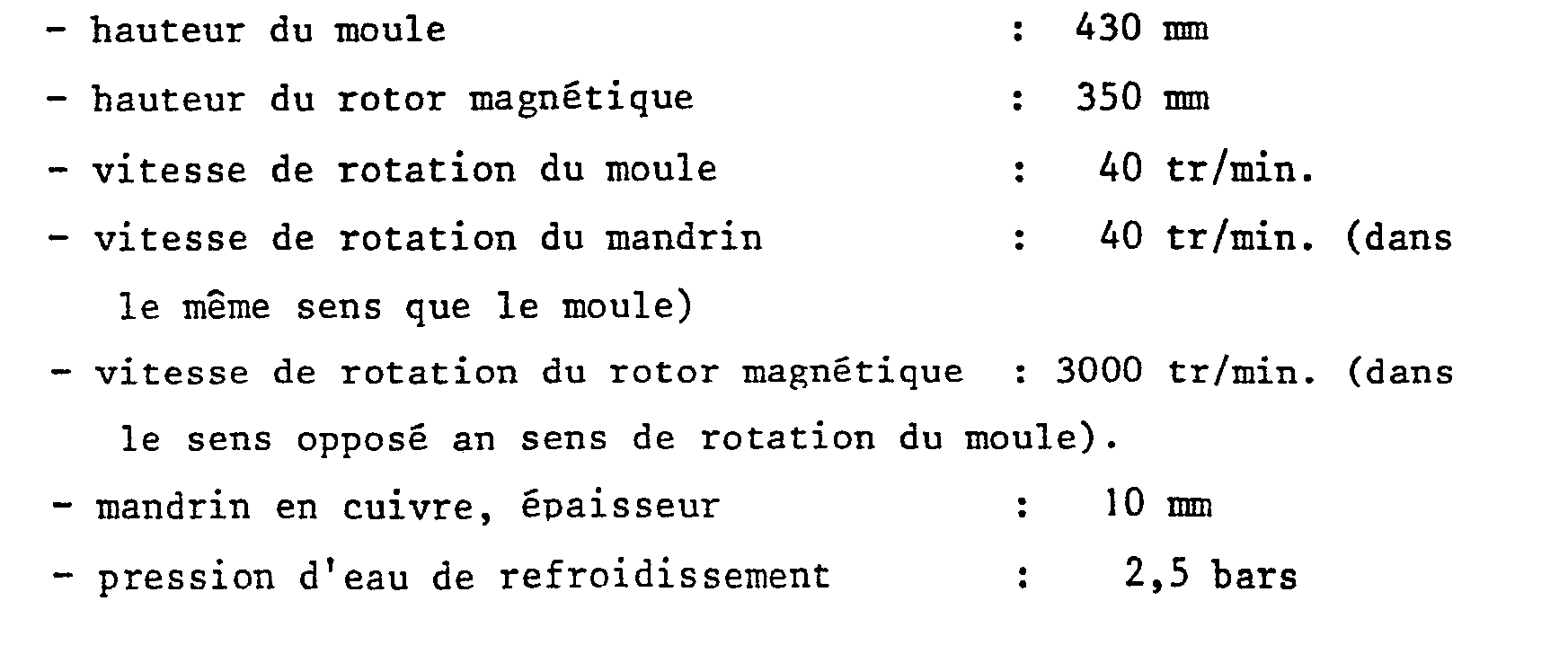
Bien que l'exemple qui vient d'être donné concerne l'application du procédé suivant l'invention, à la coulée continue rotative, c'est-à-dire au cas où le corps creux coulé est entraîné en rotation ainsi que le moule, le procédé suivant l'invention s'applique également de la façon la plus générale aux procédés dans lesquels le moule est fixe.Although the example which has just been given relates to the application of the method according to the invention, to rotary continuous casting, that is to say in the case where the cast hollow body is driven in rotation thus as the mold, the method according to the invention also applies more generally to the processes in which the mold is fixed.
Ainsi que cela a été décrit plus haut, il est également possible de réaliser le procédé suivant l'invention en faisant appel à un champ magnétique mobile obtenu non pas au moyen d'un rotor magnétique, mais au moyen d'un inducteur comportant des enroulements alimentés en courant alternatif polyphasé.As described above, it is also possible to carry out the method according to the invention by using a mobile magnetic field obtained not by means of a magnetic rotor, but by means of an inductor comprising windings supplied with polyphase alternating current.
L'utilisation de tels inducteurs comportant par exemple des enroulements alimentés en courant triphasé est connue pour le pompage de métaux liquides tels que le sodium et même l'aluminium.The use of such inductors comprising, for example, windings supplied with three-phase current is known for pumping liquid metals such as sodium and even aluminum.
Leur structure correspond sensiblement à celle d'une portion de stator de moteur à courant alternatif polyphasé dont la courbure est annulée de façon à obtenir un champ magnétique glissant dont le mouvement de translation est linéaire.Their structure corresponds substantially to that of a portion of a polyphase alternating current motor stator whose curvature is canceled so as to obtain a sliding magnetic field whose translational movement is linear.
Dans le cas du procédé suivant l'invention on peut loger à l'intérieur du mandrin, à la place d'un rotor,un inducteur constitué par un cylindre à axe vertical en matériau magnétique comportant sur sa paroi extérieure cylindrique des encoches en saillie dans lesquelles sont disposées des séries de bobines alimentées en courant alternatif polyphasé.In the case of the method according to the invention, an inductor constituted by a cylinder with a vertical axis made of magnetic material may be housed inside the mandrel, in place of a rotor, having notches protruding in its cylindrical outer wall. which are arranged in series of coils supplied with polyphase alternating current.
On peut en particulier, dans le cas d'une alimentation en courant triphasé, utiliser 3 séries de bobines qui sont disposées dans les encoches du cylindre magnétique de façon que, lorsqu'elles sont alimentées en courant alternatif, on obtienne un champ électromagnétique glissant qui se déplace parallèlement aux génératrices du cylindre. La vitesse "V" de translation du champ est égale au produit du pas de l'enroulement "1" par la fréquence "f" du courant alternatif. Les bobines sont connectées à la source de courant triphasé de façon que le glissement vertical du champ se produise de bas en haut.One can in particular, in the case of a three-phase current supply, use 3 series of coils which are arranged in the notches of the magnetic cylinder so that, when they are supplied with alternating current, one obtains a sliding electromagnetic field which moves parallel to the generatrices of the cylinder. The field translation speed "V" is equal to the product of the pitch of the winding "1" by the frequency "f" of the alternating current. The coils are connected to the three-phase current source so that the vertical sliding of the field occurs from bottom to top.
On ajuste la vitesse de translation en agissant d'une part sur le pas du bobinage et d'autre part, éventuellement, sur la fréquence du courant polyphasé utilisé.The translation speed is adjusted by acting on the one hand on the winding pitch and on the other hand, possibly, on the frequency of the polyphase current used.
De façon préférentielle, le cylindre est fixe de façon à entraîner verticalement le métal liquide dans la zone voisine du mandrin. Dans ce cas, le champ magnétique mobile ne comporte pas de composante horizontale tendant à entraîner le métal liquide en rotation. Lorsqu'on utilise un procédé de coulée continue rotative, l'inducteur accompagne de préférence le mandrin dans son mouvement de rotation.Preferably, the cylinder is fixed so as to vertically entrain the liquid metal in the region adjacent to the mandrel. In this case, the mobile magnetic field does not have a horizontal component tending to drive the liquid metal in rotation. When using a rotary continuous casting process, the inductor preferably accompanies the mandrel in its rotational movement.
De très nombreuses variantes d'exécution peuvent être apportées au procédé et au dispositif qui font l'objet de l'invention, sans sortir du domaine de celle-ci.Numerous variant embodiments can be made to the method and to the device which are the subject of the invention, without departing from the field of the latter.
Claims (31)
Priority Applications (1)
| Application Number | Priority Date | Filing Date | Title |
|---|---|---|---|
| AT82420179T ATE20645T1 (en) | 1982-01-13 | 1982-12-16 | PROCESS AND PLANT FOR CONTINUOUS CASTING OF HOLLOW BODIES USING MAGNETIC FIELDS. |
Applications Claiming Priority (2)
| Application Number | Priority Date | Filing Date | Title |
|---|---|---|---|
| FR8200763 | 1982-01-13 | ||
| FR8200763A FR2519567A1 (en) | 1982-01-13 | 1982-01-13 | METHOD FOR MANUFACTURING HOLLOW BODIES BY CONTINUOUS CASTING USING A MAGNETIC FIELD AND DEVICE FOR CARRYING OUT THE METHOD |
Publications (3)
| Publication Number | Publication Date |
|---|---|
| EP0083898A2 true EP0083898A2 (en) | 1983-07-20 |
| EP0083898A3 EP0083898A3 (en) | 1983-10-05 |
| EP0083898B1 EP0083898B1 (en) | 1986-07-09 |
Family
ID=9270112
Family Applications (1)
| Application Number | Title | Priority Date | Filing Date |
|---|---|---|---|
| EP82420179A Expired EP0083898B1 (en) | 1982-01-13 | 1982-12-16 | Process and apparatus for continuously casting hollow products employing a magnetic field |
Country Status (14)
| Country | Link |
|---|---|
| US (2) | US4729422A (en) |
| EP (1) | EP0083898B1 (en) |
| JP (1) | JPS58122161A (en) |
| AR (1) | AR229379A1 (en) |
| AT (1) | ATE20645T1 (en) |
| BR (1) | BR8300118A (en) |
| CA (1) | CA1195823A (en) |
| DE (1) | DE3271958D1 (en) |
| ES (1) | ES8400904A1 (en) |
| FR (1) | FR2519567A1 (en) |
| IN (1) | IN158299B (en) |
| MX (1) | MX159339A (en) |
| SU (1) | SU1591801A3 (en) |
| ZA (1) | ZA83230B (en) |
Cited By (1)
| Publication number | Priority date | Publication date | Assignee | Title |
|---|---|---|---|---|
| US4570698A (en) * | 1983-09-21 | 1986-02-18 | Asea Aktiebolag | Method of and apparatus for centrifugal casting |
Families Citing this family (14)
| Publication number | Priority date | Publication date | Assignee | Title |
|---|---|---|---|---|
| US6037167A (en) * | 1994-10-03 | 2000-03-14 | Ericomp | Magnetic polynucleotide separation and analysis |
| US6059015A (en) * | 1997-06-26 | 2000-05-09 | General Electric Company | Method for directional solidification of a molten material and apparatus therefor |
| US6845809B1 (en) | 1999-02-17 | 2005-01-25 | Aemp Corporation | Apparatus for and method of producing on-demand semi-solid material for castings |
| US6402367B1 (en) | 2000-06-01 | 2002-06-11 | Aemp Corporation | Method and apparatus for magnetically stirring a thixotropic metal slurry |
| US6796362B2 (en) | 2000-06-01 | 2004-09-28 | Brunswick Corporation | Apparatus for producing a metallic slurry material for use in semi-solid forming of shaped parts |
| US6432160B1 (en) * | 2000-06-01 | 2002-08-13 | Aemp Corporation | Method and apparatus for making a thixotropic metal slurry |
| US6399017B1 (en) * | 2000-06-01 | 2002-06-04 | Aemp Corporation | Method and apparatus for containing and ejecting a thixotropic metal slurry |
| US6742567B2 (en) * | 2001-08-17 | 2004-06-01 | Brunswick Corporation | Apparatus for and method of producing slurry material without stirring for application in semi-solid forming |
| LU91086B1 (en) * | 2004-06-25 | 2005-12-27 | Sms Demag Ag | Continous casting mould wit oscillation device. |
| EP2411170B1 (en) * | 2009-03-27 | 2015-09-30 | Titanium Metals Corporation | Method and apparatus for semi-continuous casting of hollow ingots and products resulting therefrom |
| AT509495B1 (en) * | 2010-03-02 | 2012-01-15 | Inteco Special Melting Technologies Gmbh | METHOD AND APPENDIX FOR PRODUCING HOLLOWING TRANSPARENCIES |
| KR101042295B1 (en) * | 2010-08-12 | 2011-06-17 | 동신산업(주) | Cavity and core changing type foam-forming mold |
| RU2517094C1 (en) * | 2013-01-30 | 2014-05-27 | Открытое акционерное общество Акционерная холдинговая компания "Всероссийский научно-исследовательский и проектно-конструкторский институт металлургического машиностроения имени академика Целикова" (ОАО АХК "ВНИИМЕТМАШ") | Hollow blank continuous casting machine mould mandrel |
| RU2516414C1 (en) * | 2013-01-30 | 2014-05-20 | Открытое акционерное общество Акционерная холдинговая компания "Всероссийский научно-исследовательский и проектно-конструкторский институт металлургического машиностроения имени академика Целикова" (ОАО АХК "ВНИИМЕТМАШ") | Mandrel with variable taper of working surface for crystalliser of machine for continuous casting of hollow billets |
Citations (10)
| Publication number | Priority date | Publication date | Assignee | Title |
|---|---|---|---|---|
| FR1064849A (en) * | 1952-10-16 | 1954-05-18 | Improvements to continuous casting molds for metals and in particular steel | |
| FR1140200A (en) * | 1955-01-15 | 1957-07-16 | Boehler & Co Ag Geb | Process for moving molten metal in continuous casting plants |
| FR1181997A (en) * | 1957-09-04 | 1959-06-19 | Ile D Etudes De Centrifugation | Continuous demolding centrifugal casting process and equipment for implementing this process |
| FR1254431A (en) * | 1960-01-09 | 1961-02-24 | Ile D Etudes De Centrifugation | Method for the rotary casting of metals with continuous demoulding and device for carrying out this method |
| FR1385730A (en) * | 1964-01-02 | 1965-01-15 | North American Aviation Inc | Electromagnetic pump |
| FR2358222A1 (en) * | 1976-07-13 | 1978-02-10 | Siderurgie Fse Inst Rech | NEW PROCESS AND DEVICE FOR THE ELECTROMAGNETIC BREWING OF CONTINUOUS FLOWING METAL PRODUCTS |
| FR2373729A1 (en) * | 1976-12-13 | 1978-07-07 | Autoclave Eng Inc | MAGNETIC TRANSMISSION |
| FR2457031A1 (en) * | 1979-05-15 | 1980-12-12 | Lucas Industries Ltd | METHOD FOR ASSEMBLING A PERMANENT MAGNET ROTOR |
| EP0022711A1 (en) * | 1979-07-12 | 1981-01-21 | Cem Compagnie Electro-Mecanique | Process and agitating means for ameliorating the quality of continuous cast metals |
| US4296544A (en) * | 1978-12-26 | 1981-10-27 | The Garrett Corporation | Method of making rotor assembly with magnet cushions |
Family Cites Families (13)
| Publication number | Priority date | Publication date | Assignee | Title |
|---|---|---|---|---|
| US3416591A (en) * | 1963-03-27 | 1968-12-17 | Civile Soc Civile D Etudes De | Process for effecting the continuous rotary casting of hollow steel blanks |
| AT286521B (en) * | 1968-05-22 | 1970-12-10 | Mannesmann Ag | Device for internal cooling of hollow strands |
| US3844332A (en) * | 1971-11-05 | 1974-10-29 | R Bucci | Making seamless tubing by continuous process |
| FR2180494A1 (en) * | 1972-04-18 | 1973-11-30 | Etudes De Centrifugation | Continuous rotative casting - produces hollow blanks with good internal and external surface qualities |
| US4042007A (en) * | 1975-04-22 | 1977-08-16 | Republic Steel Corporation | Continuous casting of metal using electromagnetic stirring |
| JPS5326731A (en) * | 1976-08-26 | 1978-03-13 | Fuji Kogyosho Kk | Method of manufacturing metal pipe |
| CH618363A5 (en) * | 1977-01-06 | 1980-07-31 | Getselev Zinovy N | Electromagnetic mould for the continuous and semi-continuous casting of hollow strands |
| JPS5425222A (en) * | 1977-07-29 | 1979-02-26 | Fuji Kogyosho Kk | Method of making metal pipes |
| FR2415501A1 (en) * | 1978-01-27 | 1979-08-24 | Pont A Mousson | PROCESS AND PLANT FOR CONTINUOUS CASTING OF TUBULAR PRODUCTS |
| JPS55106664A (en) * | 1979-02-05 | 1980-08-15 | Nippon Kokan Kk <Nkk> | Continuous casting method of steel by electromagnetic agitation |
| JPS5842780B2 (en) * | 1980-03-28 | 1983-09-21 | 住友金属工業株式会社 | Electromagnetic stirring method and device |
| GB2103131B (en) * | 1981-07-28 | 1986-03-12 | Sumitomo Metal Ind | Magnetic stirring of molten metal in a mould utilizing permanent magnets |
| US4614225A (en) * | 1982-12-10 | 1986-09-30 | Vallourec | Magnetic rotor for the continuous casting of hollow bodies |
-
1982
- 1982-01-13 FR FR8200763A patent/FR2519567A1/en active Granted
- 1982-12-16 AT AT82420179T patent/ATE20645T1/en not_active IP Right Cessation
- 1982-12-16 DE DE8282420179T patent/DE3271958D1/en not_active Expired
- 1982-12-16 EP EP82420179A patent/EP0083898B1/en not_active Expired
-
1983
- 1983-01-10 AR AR291826A patent/AR229379A1/en active
- 1983-01-10 JP JP58002759A patent/JPS58122161A/en active Granted
- 1983-01-11 MX MX195890A patent/MX159339A/en unknown
- 1983-01-11 SU SU833532551A patent/SU1591801A3/en active
- 1983-01-12 ES ES518919A patent/ES8400904A1/en not_active Expired
- 1983-01-12 CA CA000419288A patent/CA1195823A/en not_active Expired
- 1983-01-12 BR BR8300118A patent/BR8300118A/en not_active IP Right Cessation
- 1983-01-13 IN IN56/CAL/83A patent/IN158299B/en unknown
- 1983-01-13 ZA ZA83230A patent/ZA83230B/en unknown
-
1985
- 1985-11-08 US US06/797,773 patent/US4729422A/en not_active Expired - Fee Related
-
1989
- 1989-05-01 US US07/346,267 patent/US4974660A/en not_active Expired - Fee Related
Patent Citations (10)
| Publication number | Priority date | Publication date | Assignee | Title |
|---|---|---|---|---|
| FR1064849A (en) * | 1952-10-16 | 1954-05-18 | Improvements to continuous casting molds for metals and in particular steel | |
| FR1140200A (en) * | 1955-01-15 | 1957-07-16 | Boehler & Co Ag Geb | Process for moving molten metal in continuous casting plants |
| FR1181997A (en) * | 1957-09-04 | 1959-06-19 | Ile D Etudes De Centrifugation | Continuous demolding centrifugal casting process and equipment for implementing this process |
| FR1254431A (en) * | 1960-01-09 | 1961-02-24 | Ile D Etudes De Centrifugation | Method for the rotary casting of metals with continuous demoulding and device for carrying out this method |
| FR1385730A (en) * | 1964-01-02 | 1965-01-15 | North American Aviation Inc | Electromagnetic pump |
| FR2358222A1 (en) * | 1976-07-13 | 1978-02-10 | Siderurgie Fse Inst Rech | NEW PROCESS AND DEVICE FOR THE ELECTROMAGNETIC BREWING OF CONTINUOUS FLOWING METAL PRODUCTS |
| FR2373729A1 (en) * | 1976-12-13 | 1978-07-07 | Autoclave Eng Inc | MAGNETIC TRANSMISSION |
| US4296544A (en) * | 1978-12-26 | 1981-10-27 | The Garrett Corporation | Method of making rotor assembly with magnet cushions |
| FR2457031A1 (en) * | 1979-05-15 | 1980-12-12 | Lucas Industries Ltd | METHOD FOR ASSEMBLING A PERMANENT MAGNET ROTOR |
| EP0022711A1 (en) * | 1979-07-12 | 1981-01-21 | Cem Compagnie Electro-Mecanique | Process and agitating means for ameliorating the quality of continuous cast metals |
Cited By (1)
| Publication number | Priority date | Publication date | Assignee | Title |
|---|---|---|---|---|
| US4570698A (en) * | 1983-09-21 | 1986-02-18 | Asea Aktiebolag | Method of and apparatus for centrifugal casting |
Also Published As
| Publication number | Publication date |
|---|---|
| ZA83230B (en) | 1983-10-26 |
| CA1195823A (en) | 1985-10-29 |
| IN158299B (en) | 1986-10-11 |
| SU1591801A3 (en) | 1990-09-07 |
| US4729422A (en) | 1988-03-08 |
| US4974660A (en) | 1990-12-04 |
| DE3271958D1 (en) | 1986-08-14 |
| JPS6352981B2 (en) | 1988-10-20 |
| AR229379A1 (en) | 1983-07-29 |
| EP0083898A3 (en) | 1983-10-05 |
| BR8300118A (en) | 1983-10-04 |
| FR2519567B1 (en) | 1984-10-19 |
| MX159339A (en) | 1989-05-17 |
| EP0083898B1 (en) | 1986-07-09 |
| ES518919A0 (en) | 1983-11-16 |
| ES8400904A1 (en) | 1983-11-16 |
| JPS58122161A (en) | 1983-07-20 |
| ATE20645T1 (en) | 1986-07-15 |
| FR2519567A1 (en) | 1983-07-18 |
Similar Documents
| Publication | Publication Date | Title |
|---|---|---|
| EP0083898B1 (en) | Process and apparatus for continuously casting hollow products employing a magnetic field | |
| EP0439981B1 (en) | Process and device for manufacturing metallic thixotropic products by continuous casting and electromagnetic stirring | |
| CA1231510A (en) | Magnetic rotor for continuous molding of hollow objects | |
| CA2059081C (en) | Static elctromagnetic inductor making process | |
| CA2391235C (en) | Method for vertical continuous casting of metals using electromagnetic fields and casting installation therefor | |
| FR2624419A1 (en) | ELECTROMAGNETIC COUPLING DISC AND MANUFACTURING METHOD THEREOF | |
| EP0351327A1 (en) | Method for fabrication of thixotrope metallic products by continuous casting | |
| CA1293845C (en) | Method and device for grooving the face of a cylindrical object | |
| EP3706934B1 (en) | Device and method for manufacturing a metal alloy blank by centrifugal casting | |
| FR2856321A1 (en) | CONTINUOUS CASTING INSTALLATION FOR ELECTRO-MAGNETIC ROTATION OF LIQUID METAL IN TRANSIT IN THE CASTING BUSH | |
| LU88034A1 (en) | Electromagnetic stirring process in continuous casting | |
| FR2537470A2 (en) | Magnetic rotor for continuous casting of hollow bodies | |
| EP0187609A1 (en) | Apparatus for the rotating feeding of a cast to a vertical continuous-casting plant for spheroidal graphite cast iron tubes | |
| EP0022711B1 (en) | Process and agitating means for ameliorating the quality of continuous cast metals | |
| CA2398724C (en) | Equipment for supplying molten metal to a continuous casting ingot mould and method for using same | |
| EP0241387B1 (en) | Casting mould for the regulation of the free surface level of the molten metal contacting the mould during vertical casting | |
| FR2614222A1 (en) | IMPROVEMENT TO THE PROCESS OF SOLIDIFYING LIQUID METAL IN A CASTING WHEEL. | |
| CN208758612U (en) | Aluminium slag filter device | |
| FR2581687A1 (en) | Machine for producing shrinkage joints in compacted concrete slabs | |
| FR2593417A1 (en) | ROLLER OF OBLIQUE CYLINDERS TUBES | |
| FR2769424A1 (en) | Electric vehicle synchronous traction motor with permanent magnet rotor. | |
| EP0290423B1 (en) | Device for continuously manufacturing a thin metal strip | |
| FR2626904A1 (en) | PROCESS FOR MANUFACTURING COMBINED METALLIC ARTICLES SUCH AS ELECTRIC CABLES, HANDLING CABLES AND MULTIFILAR METAL ROPES | |
| BE886897A (en) | METHOD AND APPARATUS FOR COATING DAIRY PARTS | |
| CN107697437A (en) | Rotatable drawing type target storage cabin |
Legal Events
| Date | Code | Title | Description |
|---|---|---|---|
| PUAI | Public reference made under article 153(3) epc to a published international application that has entered the european phase |
Free format text: ORIGINAL CODE: 0009012 |
|
| AK | Designated contracting states |
Designated state(s): AT BE CH DE GB IT LI LU NL SE |
|
| PUAL | Search report despatched |
Free format text: ORIGINAL CODE: 0009013 |
|
| AK | Designated contracting states |
Designated state(s): AT BE CH DE GB IT LI LU NL SE |
|
| 17P | Request for examination filed |
Effective date: 19831108 |
|
| GRAA | (expected) grant |
Free format text: ORIGINAL CODE: 0009210 |
|
| AK | Designated contracting states |
Kind code of ref document: B1 Designated state(s): AT BE CH DE GB IT LI LU NL SE |
|
| REF | Corresponds to: |
Ref document number: 20645 Country of ref document: AT Date of ref document: 19860715 Kind code of ref document: T |
|
| REF | Corresponds to: |
Ref document number: 3271958 Country of ref document: DE Date of ref document: 19860814 |
|
| ITF | It: translation for a ep patent filed |
Owner name: ING. A. GIAMBROCONO & C. S.R.L. |
|
| PLBE | No opposition filed within time limit |
Free format text: ORIGINAL CODE: 0009261 |
|
| STAA | Information on the status of an ep patent application or granted ep patent |
Free format text: STATUS: NO OPPOSITION FILED WITHIN TIME LIMIT |
|
| 26N | No opposition filed | ||
| PGFP | Annual fee paid to national office [announced via postgrant information from national office to epo] |
Ref country code: GB Payment date: 19921111 Year of fee payment: 11 |
|
| PGFP | Annual fee paid to national office [announced via postgrant information from national office to epo] |
Ref country code: DE Payment date: 19921112 Year of fee payment: 11 |
|
| PGFP | Annual fee paid to national office [announced via postgrant information from national office to epo] |
Ref country code: CH Payment date: 19921113 Year of fee payment: 11 |
|
| PGFP | Annual fee paid to national office [announced via postgrant information from national office to epo] |
Ref country code: SE Payment date: 19921116 Year of fee payment: 11 Ref country code: AT Payment date: 19921116 Year of fee payment: 11 |
|
| PGFP | Annual fee paid to national office [announced via postgrant information from national office to epo] |
Ref country code: LU Payment date: 19921202 Year of fee payment: 11 |
|
| PGFP | Annual fee paid to national office [announced via postgrant information from national office to epo] |
Ref country code: BE Payment date: 19921204 Year of fee payment: 11 |
|
| PGFP | Annual fee paid to national office [announced via postgrant information from national office to epo] |
Ref country code: NL Payment date: 19921231 Year of fee payment: 11 |
|
| EPTA | Lu: last paid annual fee | ||
| PG25 | Lapsed in a contracting state [announced via postgrant information from national office to epo] |
Ref country code: LU Free format text: LAPSE BECAUSE OF NON-PAYMENT OF DUE FEES Effective date: 19931216 Ref country code: GB Effective date: 19931216 Ref country code: AT Effective date: 19931216 |
|
| PG25 | Lapsed in a contracting state [announced via postgrant information from national office to epo] |
Ref country code: SE Effective date: 19931217 |
|
| ITTA | It: last paid annual fee | ||
| PG25 | Lapsed in a contracting state [announced via postgrant information from national office to epo] |
Ref country code: LI Effective date: 19931231 Ref country code: CH Effective date: 19931231 Ref country code: BE Effective date: 19931231 |
|
| BERE | Be: lapsed |
Owner name: VALLOUREC Effective date: 19931231 |
|
| PG25 | Lapsed in a contracting state [announced via postgrant information from national office to epo] |
Ref country code: NL Effective date: 19940701 |
|
| GBPC | Gb: european patent ceased through non-payment of renewal fee |
Effective date: 19931216 |
|
| NLV4 | Nl: lapsed or anulled due to non-payment of the annual fee | ||
| REG | Reference to a national code |
Ref country code: CH Ref legal event code: PL |
|
| PG25 | Lapsed in a contracting state [announced via postgrant information from national office to epo] |
Ref country code: DE Effective date: 19940901 |
|
| EUG | Se: european patent has lapsed |
Ref document number: 82420179.2 Effective date: 19940710 |