EP0082007B1 - Vorrichtung zum Messen der Dicke eines Films - Google Patents
Vorrichtung zum Messen der Dicke eines Films Download PDFInfo
- Publication number
- EP0082007B1 EP0082007B1 EP82306642A EP82306642A EP0082007B1 EP 0082007 B1 EP0082007 B1 EP 0082007B1 EP 82306642 A EP82306642 A EP 82306642A EP 82306642 A EP82306642 A EP 82306642A EP 0082007 B1 EP0082007 B1 EP 0082007B1
- Authority
- EP
- European Patent Office
- Prior art keywords
- film
- light
- measuring
- measured
- thickness
- Prior art date
- Legal status (The legal status is an assumption and is not a legal conclusion. Google has not performed a legal analysis and makes no representation as to the accuracy of the status listed.)
- Expired
Links
- 230000003287 optical effect Effects 0.000 claims description 57
- 238000010438 heat treatment Methods 0.000 claims description 5
- 238000005192 partition Methods 0.000 claims description 5
- 238000002347 injection Methods 0.000 claims description 3
- 239000007924 injection Substances 0.000 claims description 3
- 238000005259 measurement Methods 0.000 description 33
- 238000000034 method Methods 0.000 description 22
- 229920006267 polyester film Polymers 0.000 description 16
- 238000004519 manufacturing process Methods 0.000 description 12
- 238000012545 processing Methods 0.000 description 11
- 238000010521 absorption reaction Methods 0.000 description 9
- 239000013307 optical fiber Substances 0.000 description 8
- 238000001514 detection method Methods 0.000 description 7
- 239000000463 material Substances 0.000 description 7
- 238000010586 diagram Methods 0.000 description 6
- 238000005070 sampling Methods 0.000 description 6
- 230000008859 change Effects 0.000 description 4
- 238000006243 chemical reaction Methods 0.000 description 4
- WPYVAWXEWQSOGY-UHFFFAOYSA-N indium antimonide Chemical compound [Sb]#[In] WPYVAWXEWQSOGY-UHFFFAOYSA-N 0.000 description 3
- 230000005855 radiation Effects 0.000 description 3
- 230000004044 response Effects 0.000 description 3
- 238000002834 transmittance Methods 0.000 description 3
- VYPSYNLAJGMNEJ-UHFFFAOYSA-N Silicium dioxide Chemical compound O=[Si]=O VYPSYNLAJGMNEJ-UHFFFAOYSA-N 0.000 description 2
- 230000002411 adverse Effects 0.000 description 2
- 238000005266 casting Methods 0.000 description 2
- 230000004048 modification Effects 0.000 description 2
- 238000012986 modification Methods 0.000 description 2
- 239000002120 nanofilm Substances 0.000 description 2
- 229910001120 nichrome Inorganic materials 0.000 description 2
- 239000004033 plastic Substances 0.000 description 2
- 230000008569 process Effects 0.000 description 2
- 239000004065 semiconductor Substances 0.000 description 2
- 230000000087 stabilizing effect Effects 0.000 description 2
- 230000001360 synchronised effect Effects 0.000 description 2
- 239000000919 ceramic Substances 0.000 description 1
- 238000010276 construction Methods 0.000 description 1
- 238000011109 contamination Methods 0.000 description 1
- 238000002474 experimental method Methods 0.000 description 1
- 238000001125 extrusion Methods 0.000 description 1
- 238000001914 filtration Methods 0.000 description 1
- 230000007246 mechanism Effects 0.000 description 1
- 229920002120 photoresistant polymer Polymers 0.000 description 1
- 239000002985 plastic film Substances 0.000 description 1
- 229920006255 plastic film Polymers 0.000 description 1
- 230000035945 sensitivity Effects 0.000 description 1
- 238000000926 separation method Methods 0.000 description 1
- 238000012883 sequential measurement Methods 0.000 description 1
- 235000012239 silicon dioxide Nutrition 0.000 description 1
- 239000000377 silicon dioxide Substances 0.000 description 1
- 238000002798 spectrophotometry method Methods 0.000 description 1
- WFKWXMTUELFFGS-UHFFFAOYSA-N tungsten Chemical compound [W] WFKWXMTUELFFGS-UHFFFAOYSA-N 0.000 description 1
Images


Classifications
-
- G—PHYSICS
- G01—MEASURING; TESTING
- G01B—MEASURING LENGTH, THICKNESS OR SIMILAR LINEAR DIMENSIONS; MEASURING ANGLES; MEASURING AREAS; MEASURING IRREGULARITIES OF SURFACES OR CONTOURS
- G01B11/00—Measuring arrangements characterised by the use of optical techniques
- G01B11/02—Measuring arrangements characterised by the use of optical techniques for measuring length, width or thickness
- G01B11/06—Measuring arrangements characterised by the use of optical techniques for measuring length, width or thickness for measuring thickness ; e.g. of sheet material
- G01B11/0691—Measuring arrangements characterised by the use of optical techniques for measuring length, width or thickness for measuring thickness ; e.g. of sheet material of objects while moving
-
- G—PHYSICS
- G01—MEASURING; TESTING
- G01B—MEASURING LENGTH, THICKNESS OR SIMILAR LINEAR DIMENSIONS; MEASURING ANGLES; MEASURING AREAS; MEASURING IRREGULARITIES OF SURFACES OR CONTOURS
- G01B11/00—Measuring arrangements characterised by the use of optical techniques
- G01B11/02—Measuring arrangements characterised by the use of optical techniques for measuring length, width or thickness
- G01B11/06—Measuring arrangements characterised by the use of optical techniques for measuring length, width or thickness for measuring thickness ; e.g. of sheet material
- G01B11/0616—Measuring arrangements characterised by the use of optical techniques for measuring length, width or thickness for measuring thickness ; e.g. of sheet material of coating
Definitions
- the present invention relates to apparatus for measuring the thickness of a film, more particularly to apparatus for in-process sequential measurement of the thickness of high molecular continuous film during the production of the high molecular film by utilization. of its optical characteristics.
- the present invention also relates to an apparatus containing an optical and electric arrangement to carry out the method.
- a typical method for in-line measurement of film thickness disclosed in Japanese Unexamined Patent Publication No. 53-31155, employs an infrared ray thickness measuring device which includes two alternatively switchable optical filters, one being used for transmitting an infrared ray of a peak-absorption wavelength that is strongly absorbed by the film to be measured and the other being used for transmitting an infrared ray of a non-absorption wavelength that is substantially not absorbed by the film.
- the two infrared rays are alternately passed through the same optical path.
- This known method is very effective for stable sequential thickness measurement of films, but suffers from some problem. Specifically, when a large change in the film thickness occurs or when the atmospheric temperature changes, the transmittance of the infrared rays of both the peak-absorption and non-absorption wavelengths does not change accordingly, thereby causing errors in measurement of the film thickness. Also, with small thicknesses of the measured film, the amount of infrared rays absorbed by the film is small, resulting in low sensitivity and accuracy of thickness measurement and making it difficult to detect change in the thickness of the continuous film. Further, the alternative use of the infrared rays of the peak-absorption wavelength and the non-absorption wavelength makes it impossible to continuously measure the film thickness and limit the response speed in the measurement. The latter problems are particularly serious since the recent production speed of the films is as high as several hundred meters per minute and since the response speed in the in-process measurement of films must be more than several dozen milliseconds.
- An object of the present invention is therefore to provide apparatus for in-process measurement of the thickness of high molecular continuous films during production thereof.
- Another object of the present invention is to provide apparatus for accurately measuring the thickness of the high molecular films varying in thickness from less than several pm (micrometer) to several hundred pm.
- the present invention provides apparatus for carrying out such measurements, as set out in the claims appended hereto.
- FR-A-2 435 696 discloses, inter alia, a method and apparatus for measuring the wall thickness of plastic articles such as bottles having rotational symmetry using radiation from a source within the article. The radiation is chopped by a rotating shutter so as to provide an AC output signal which can be amplified and filtered. The apparatus is calibrated by introducing a standard plastic plate when no article is being measured.
- GB-A-2 077 426 relates to the measurement of very thin plastic film using infrared radiation. IEEE Transactors on Electron Devices, Vol. ED-22 7th July 1975 pp 452-456 discloses a spectro photometric method suitable for measuring the changes in the thickness of silicon dioxide films or photoresist layers.
- a film P for example, polyester film
- a film P is measured for thickness while running through the extrusion stage, casting orfilm-forming stage, and stretching stage of the production line.
- a piece of film S made of the same material is used as a reference for the thickness measurement.
- the thickness of the reference film S is selected to correspond to the desired production thickness of the film P.
- the reference film S comprisss a piece of film cut out of the film P and inspected for accuracy.
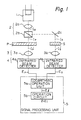
- a light source 1 is arranged for generating the beam of light for measurement of the thickness of the film P.
- a nichrome wire heater capable of generating an infrared beam lo having a wavelength of 5.8 pm is employed as the light source 1. This is because the absorption coefficient of polyester film against such an infrared beam is approximately 1.0.
- An optical projecting system 2 consisting of conventional optical elements, such as a convex lens 2a, a half mirror 2b, and a reflecting mirror 2c, splits the incident infrared beam lo into a measuring beam Ip incident upon the measured film P and a reference beam Is incident upon the reference film S.
- An optical receiving system 3 consisting of convex lenses 3a and 3b is provided for bringing a reference beam I's, transmitted through the reference film S, and a measuring beam I'p, transmitted through the measured film P, to a photoelectric converting unit 4 consists of infrared beam detectors 4a and 4b having a high sensibility to the infrared beam.
- the infrared beam detectors 4a and 4b can be commercially available InSb semiconductors, for example, InSb. detector No. IRS-311S manufactured by Fujitsu Limited, Japan.
- the infrared beam detectors 4a and 4b convert beams I'p and I's into electric signals Ep and Es, respectively.
- the magnitudes of electric signals Ep and Es are proportional to the amount of the infrared beam I'p and I's received by the detectors 4a and 4b.
- a signal processing unit 5 is provided for producing an electric signal Et, corresponding to the thickness t of the measured film P by electrically processing the electric signals Ep and Es.
- the signal processing unit 5 includes a logarithmic operation unit 5a consisting of a pair of logarithmic amplifiers, for example, those manufactured and sold by Intersil Inc., U.S.A., und Part No. ICL 8048, and a conventional differential amplifier.
- the logarithmic operation unit 5a is provided for generating a signal E1 corresponding to the value log EP/ES.
- the signal processing unit 5 also includes an operational circuit 5b consisting of a conventional operational amplifier.
- the operational circuit 5b is provided for adding the output signal E1 and a predetermined electric signal corresponding to the known thickness to of the reference film S to produce the electric signal Et.
- the a mount i'p of the measuring beam I'p received by the infrared beam detector 4a and the amount i' s of the reference beam Is received by the infrared beam detector 4b are given by the following known equations.
- Kp and Ks are proportional constants related to the reflection of the beams by the polyester films P and S, respectively.
- the infrared beam detectors 4a and 4b convert the amounts i'p and i' s into proportional electric signals Ep and Es, respectively. Therefore, if the conversion coefficients of both detectors 4a and 4b are assumed to be 1p and 1 5 , the electric signal E1 from the logarithmic operation unit 5a is given by the following equation.
- the reference film S and the measured film P are made of the same material and that the optical system for the reference film S is equivalent to that for the measured film P. That is, the above-mentioned proportional constants Ks and Kp can be considered to be approximately equal.
- the split ratio d of the beam of the half mirror 2b is set to 1/2 and if the conversion coefficients 1p and 1 s of the infrared beam detectors 4a and 4b are made equal, the item in equation (c) becomes approximately zero and therefore can be ignored. Accordingly, the equation (c) becomes
- any variation of the thickness t of the measured film P from the known thickness to of the reference film S can be detected by the measurement of the electric signal E1.
- This method of detection is very effective for stabilizing the electric processing operation of all signals by the electric elements and circuits used. Also, the detection can be very precise, since it is carried out through the electric measurement of the electric signal E1.
- the electrical processing operation to obtain the signal E1 is performed so as to detect the ratio of the amounts of the measuring beam Ip and the reference beam Is, changes in the performance of the light source 1, changes in the operating condition of the optical systems through which the measured and reference infrared beams Ip and Is pass, and changes in the performance of the infrared beam detectors 4a and 4b do not adversely affect the detection of the signal E1, as will be understood from equation (c).
- the electric signal E1 is processed in the operational circuit 5b for compensation of the value to related to the thickness to of the reference film S. As a result, the signal Et of the operational circuit 5b becomes
- the signal Et of the operational circuit 5b is an electric signal proportional to the thickness t of the measured film P.
- the light beam used for the measurement has to be selected so as to be one that has a wavelength most suited to the optical characteristic (absorption coefficient) of the film to be measured. That is to say, the beam of light used for embodying the method of the present invention may be selected from diverse kinds of beams, such as visible light, ultraviolet beam, and infrared and far infrared beams, in accordance with the optical characteristics of the measured film.
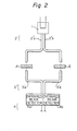
- the optical projecting and receiving systems 2 and 3 can also comprise optical fibers.
- Figure 2 illustrates an optical projecting system 2' consisting of a pair of optical fibers 2'a and 2'b and an optical receiving system 3' consisting of a pair of optical fibers 3'a and 3'b.
- the use of the optical fibers is very effective for eliminating possible errors caused by outside light or optical disturbances in the optical path.
- the use of the optical fibers is also effective for achieving ,compact arrangement of the photoelectric converting unit 4.
- the use of the optical fibers together with a pair of infrared beam detectors 4a and 4b having the same photoelectric characteristics is, particularly, very effective for simplifying the overall optical systems of the measuring arrangement of the present invention.
- the optical systems of the measuring arrangement may be formed by combination of an optical projecting system employing a lens and mirrors and an optical receiving system employing optical fibers. Further, a known beam splitter or a swingable mirror may be used for splitting the beam of light generated by the light source 1.
- the light source 1 may be formed by a laser if the overall measuring arrangement is appropriately designed, depending on where the measurement is carried out and what kind of high molecular material the measured film is made of.
- the operational circuit 5b may be deleted if it is not necessary to detect the electric signal E1 that is directly related to the absolute dimension of the thickness t of the measured film P.
- the output signal E1 of the logarithmic operation unit 5a may directly be impressed to a suitable electrical comparison circuit for comparing the signal E1 with predetermined upper and lower variation limits.
- the thickness to of the reference film S may be different from that aimed at by the production requirement of the measured film P, but should preferably be chosen so as to be equal to either the upper or lower limit thickness of the measured film P.
- the reference film S should be a piece of film taken out of the same production line as the film P to be actually measured.
- the arrangement of Fig. 1 may be provided so as to measure the thickness of either the as-cast film delivered from the casting stage of the film production process or the oriented film delivered from the stretching stage. Alternatively, the arrangement may be provided so as to measure the thickness of both the as-cast film and the oriented film. If an appropriate conventional transversing mechanism is additionally employed, the measuring method of the present invention is applicable to thickness measuring of the high molecular continuous film in the transverse direction across the width of the film in addition to the lengthwise direction.
- Figure 3 illustrates a modified beam-splitting and receiving means for use in apparatus according to the present invention. The following description will be made in reference to the case where the measured film is again a polyester film.
- a light source 101 consisting of a nichrome wire heater 101a generates an infrared beam lo having a wavelength of 5.8 pm, against which beam lo the absorption coefficient of the polyester film is approximately 1.
- An optical projecting system 102 consists of a light collecting lens 102a, a tuning-fork-controlled swinging mirror 102b, and a fixed reflector mirror 102c.
- the swinging mirror 102b is arranged for dividing the infrared beam lo into a measuring beam Ip and a reference beam Is in the time division manner.
- the swinging mirror 102b comes into the path of the infrared beam lo, the beam lo is deflected 90 degrees toward the reflector mirror 102c so as to form the measuring beam Ip.
- the measuring beam Ip is then brought by the reflector mirror 102c toward the measured film P.
- the swinging mirror 102b is away from the path of the infrared beam lo, the beam lo advances as the reference beam Is toward the reference film S.
- the motion of the swinging mirror 102b is controlled to a predetermined swinging frequency.
- the infrared beam lo as shown in (A) of Fig. 4 is divided into the beam Is, consisting of a train of optical pulses as shown in (B) of Fig.
- the measuring beam transmitted through the measured film P is identified by I'p, while the reference beam transmitted through the reference film S is identified by I's in Figs. 3 and 4.
- the reference beam I's and the measuring beam I'p are brought by an optical receiving system 103 toward a single common photoelectric converter 104.
- the optical receiving system 103 consists of a beam synthesizer 103a, for example, a half mirror, a reflector mirror 103b, and a beam collecting lens 103c.
- the beam synthesizer 103a generates a synthesized beam IM which consists of an alternate arrangement of optical pulses I'p and I's, as shown in (D) of Fig. 4.
- the photoelectric converter 104 converts the synthesized beam IM into an electric signal EM proportional to the amount of the beam IM.
- the photoelectric converter 104 may consist of an infrared beam detector, such as an InSb semiconductor as described previously with reference to Fig. 1.
- a signal processing unit 105 is provided for generating an electric signal Et corresponding to the thickness t of the measured film P.
- the unit 105 includes an electric amplifier 151 for amplifying the electric signal EM to the level suited for the electric processing thereof.
- the unit 105 also includes an electric dividing circuit 152 for dividing the amplified electric signal EM into an electric reference signal Es converted from the reference beam I's and an electric measuring signal Ep converted from the measuring beam I'p.
- the electric dividing circuit 152 includes two sample holding circuits 152a and 152b which operate in synchronization with the motion of the swinging mirror 102b.
- the unit 105 further includes a logarithmic operation circuit 153 for generating an electric signal E1 corresponding to the value of log Ep/Es and a sample holding circuit 154 for selectively issuing a part of the electric signal E1 which is synchronized with the signal Ep issued from the sample holding circuit 152b.
- the signal issued from the sample holding circuit 154 is processed by a compensation circuit 155 so that the signal E1 is added with a compensation signal Et o corresponding to the thickness to of the reference film S. That is, the compensation circuit consists of a conventional adder.
- a reference pulse generator 151 is arranged for generating reference pulses, such as clock pulses, to synchronize the operation of the electric dividing circuit 152 and the sample holding circuit 154 with the motion of the swinging mirror 102b.
- a delay circuit 157 is arranged for giving a 180 degree phase difference between the reference pulses to the sample holding circuit 152a and those to the other sample holding circuit 152b.
- a recorder 158 may be provided for recording the electric signal Et indicating the thickness t of the measured film P. All of the optical elements and the electric elements or circuits described above are conventional, therefore, a detailed description of the individual elements and circuits is omitted.
- the amount of the infrared beam lo is i o
- the transmittance of the reference and measured films S and P made of the same material is p
- the amount i'p of the pulsive measuring beam I'p transmitted through the measured film P and the amount i' s of the pulsive measuring beam I's transmitted through the reference film S are given by the following known equations.
- Kp and Ks are proportional constants related to the reflection of the beams by the films P and S, respectively, and n is the sampling time.
- the measuring beam I'p and reference beam I's are synthesized by the synthesizer 103a to the synthesized beam IM.
- the synthesized beam IM is converted by the photoelectric converter 104 into an electric signal E.
- the electric signal EM is then divided by the electric dividing circuit 152 into the electric measuring and reference signals Ep and Es.
- These electric signals Ep and Es are subsequently processed by the logarithmic operation circuit 153.
- the shapes of the two electric signals Es and Ep issued from the sample holding circuits 152a and 152b, respectively, are stepped as shown in (E) and (F) of Fig. 4.
- AT indicates the time delay for cancelling the influence of the delay of the photoelectric conversion.
- Equation (c) can be established if the sampling speed, i.e., the frequency of the motion of the swinging mirror 102b, is high enough to enable it to ignore variation in the operation of the light source 101 and the photoelectric converter 104.
- the frequency of the motion of the swinging mirror 102b should be less than several milliseconds.
- the signal E1 can be given by the following equation.
- any variation of the thickness t of the measured polyester film P from the known thickness to of the reference polyester film S can be detected by the measurement of the electric signal E1.
- This method of obtaining the signal E1 by the use of the logarithmic operation circuit 153 i.e., the method of detecting a variation of the thickness t from the known thickness to, is very effective for stabilizing the electrical processing of the signals by the electric elements and circuits used. As a result, the detection of the thickness variation per se can be made sensitive and stable.
- the method of detecting the ratio of the measuring beam I'p to the reference beam I's is effective for cancelling any variation in the operation of the light source 101, the optical condition of the optical paths through which these two beams I'p and I's pass, and the operation of the photoelectric converter 104.
- the detection of the above-mentioned ratio can be always stable.
- the sample holding circuit 154 connected to the above-mentioned logarithmic operation circuit 153 can operate so as to sample and hold the signal E1(n) coming from the circuit 153 only when the signal E1(n) is sufficiently stabilized before it enters into the circuit 154. Therefore, the intermittent output signal issuing from the sample holding circuit 154 can be considered the same as a continuous signal.
- the electric signal from the sample holding circuit 154 is supplied into the compensation circuit 155 in which a compensation operation is carried out to cancel the component to of the signal E1, which component corresponds to the known thickness to of the reference film S. As a result, a continuous signal Et given by the following equation is issued from the compensation circuit 155.
- the signal Et of equation (e) is recorded by the recorder 158.
- the signal Et may be used to control the production process of the measured polyester film P.
- the signal Et is proportional to the actual thickness of the measured film P.
- the high speed photoelectric converter 104 is employed, quick detection of the signal Et can be accomplished. Accordingly, the measuring method described above is suited for an inprocess measurement of the actual thickness of a film.
- the measuring beam is not limited to the infrared beam and may be chosen from diverse kinds of light having diverse wavelengths in accordance with the optical characteristics of the film to be measured. Therefore, the measuring beam may be an ultraviolet beam, visible light beams, infrared or far infared beams, etc.
- the arrangement of Fig. 3 may employ optical fibers, as described in connection with the arrangement of Fig. 1, for forming the optical path.
- the tuning-fork-controlled mirror 102b used in the arrangement of Fig. 3 may be replaced with a combination of a half mirror and an appropriate optical chopper device if it is possible to bring the measuring beam from the light source 101 to the photoelectric converter 104 via both the measured and reference films.
- the beam dividing operation by the swinging mirror 102b is performed so that the measuring beam lo from the light source 101 is always projected onto one of the measured and reference films P and S without any intermission.
- the sampling operation of the sample holding circuits 152a, 152b, and 154 is controlled by the reference pulse generator 156 so that the sampling timing is synchronized with the swinging motion of the swinging mirror 102b.
- the division of the measuring beam may be made in a manner that the measuring beam is intermittently brought to the measured and reference films P and S.
- the sampling operation of the sample holding circuits may be carried out in a different way if it is possible to ignore variations in the operation of the light source, the operation of the photoelectric converter, and the optical characteristics of the optical paths.
- the measuring beam transmitted through the reference film S may be sampled each time one scanning of the measuring beam is carried out.
- the dividing circuit 152 and the logarithmic operation circuit 153 may be replaced with a conventional microprocessor device. Further, as in the case of the arrangement of Fig. 1, the electric signal E1 from the logarithmic operation circuit 153 may be used for inspecting variation of the actual thickness of the measured film P from the known thickness of the reference film S.
- the thickness of the reference film S should be appropriately chosen depending on whether any change in the actual thickness of the film from the known reference thickness of the reference film or the actual thickness of the film per se should be measured. However, it is necessary that the reference film be made of the same material as the measured film so that both films have the same optical characteristics.
- the reference film S should be a piece of film cut out of the production line of the measured film P.
- Fig. 3 can be simpler than that of Fig. 1. This is because in the arrangement of Fig. 3, a single common photoelectric converter and a single amplifier are employed, while in the arrangement of Fig. 1, a pair of photoelectric converters as well as a pair of amplifiers are employed. In the latter arrangement, it is always necessary that the electric properties of the two converters and those of the two amplifiers be kept equal.
- Figure 5 illustrates a modification of the arrangement of Fig. 3.
- the tuning-fork-controlled swinging mirror 102b of Fig. 3 is replaced with a fixed half mirror 102'b.
- the synthesizer 103a of Fig. 3 is replaced with a tuning-fork-controlled swinging mirror 103'a similar to the mirror 102b of Fig. 3.
- the remaining portion of the arrangement of Fig. 5 is the same as that of Fig. 3.
- the measuring operation of the arrangement of Fig. 5 is substantially the same as that of the arrangement of Fig. 3. Therefore, the arrangement of Fig. 5 is also adapted to be used for an in-process measurement of the thickness of a high molecular film.
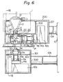
- FIGs. 6 and 7 schematically illustrate an example of apparatus according to the invention which substantially corresponds to the arrangement of Fig. 1.
- the apparatus of Figs. 6 and 7 has a rigid frame work 10 on which an upper measuring head 200 and a lower measuring head 300 are supported via cantilever arms 10a and 10b.
- the upper arm 10a and the lower arm 10b are vertically spaced apart from one another so as to give a predetermined space between the upper head 200 and the lower head 300.
- the upper and lower heads 200 and 300 are encased in upper and lower casings 201 and 301, respectively, so as to avoid contamination by dirt and foreign matter.
- the above-mentioned support of both heads 200 and 300 by the use of the cantilever arms 10a and 10b is effective for maintaining alignment of the optical axis of the upper head 200 with that of the lower head 300 even with vibration transmitted from a floor.
- a measured film P is conveyed through the space between the upper and lower heads 200 and 300. The film P is subjected to the continuous thickness measurement when it goes underneath the upper head 200.
- the upper head 200 is provided therein with a light source 1, an optical projecting system 2, a reference film S, a light collecting lens 3b, and a photoelectric converter 4b.
- the lower head 300 is provided with an optical receiving system 3, having a light collecting lens 3a, and a photoelectric converter 4a. That is to say, since the light source 1 and all the optical and electric elements related to the reference film S are compactly accommodated in the upper head 200, stable thickness measurement of the reference film S is ensured.
- the lower head 300 does not incoporate therein any optical or electrical elements related to the reference film S, no operation for adjusting the positional relationship between the upper and lower heads 200 and 300 is necessary, except for adjustment to accurately introduce a measuring beam Ip from the upper head 200 into the light collecting lens 3a of the lower head 300. As a result, the assembly operation of the entire apparatus is very easy.
- the light source 1 is provided with an upper covering 11; a conical body 12, and a heater 14.
- the upper covering 11 has therein a light reflecting wall in the shape of a partial sphere or a partial parabolic surface.
- the reflecting wall of the upper covering 11 is continuously interconnected with a conical light reflecting wall of the conical body 12.
- the upper covering 11 and the conical body 12 define therein a light generating chamber 13.
- the rod heater 14 laterally projects from the reflecting wall of the upper covering 11 into the chamber 13 so as to pass through the focus point of the spheric or parabolic reflecting wall of the covering 11.
- the heater 14 is a conventional sheathed tubular heater coated with ceramic.
- the heater 14 has therein a thermocouple, isolated from the heating wire thereof, to control the temperature of the heater 14.
- the heater 14 can generate, in the lower temperature range, a measuring infrared beam having an intermediate or long wavelength.
- the generated infrared beam is directed through an opening 15 toward the optical projecting unit 2.
- the diameter of the opening 15 is chosen to be 8 millimeters, the heater 14 heated up to 290°C could generate an infrared beam of 5.8 pm wavelength.
- the intensity of that infrared beam was as strong as that generated by a heater made of a tungsten wire and heated up to 1500°C.
- the light reflecting walls of the upper covering 11 and the conical body 12 are enveloped by an appropriate outer covering so that air heated to a predetermined temperature and predetermined humidity can be supplied under a predetermined pressure between the light reflecting walls and the outer covering.
- the infrared beam is generated at random by the heater 14 toward diverse directions and in different time phases. This is very effective for compensating for measuring error caused by the wave motion of the measuring film P conveyed between the upper and lower heads 200 and 300 during the thickness measuring process. Further, such a generated infrared beam is effective for preventing optical interference in the case of a thin measuring film. Still further, provision of the thermally controlled heater 14 is effective for stable generation of an infrared beam for a long period of time. Thus, such a heater is economical.
- the measuring beam lo is divided by a half mirror 2b held by a removable mirror holder 24 into a reference beam S and a measuring beam Ip after passing through the optical path of a cylindrical covering 21 having an inner mirror wall and a filtering element 22.
- the reference beam S is brought toward the reference film S held by an exchangeable film holder 31.
- the reference beam Is transmitted through the reference film S is brought by an optical path unit 23 toward the light collecting lens 3b.
- the reference beam S is brought by the guide of a cylindrical mirror tube 35b toward the photoelectric converter 4b, which converts the reference beam into the corresponding electric signal Es.
- a heat disperser 41 b is arranged adjacent to the photoelectric converter 4b.
- An auxiliary circuit 42b is arranged so as to be operatively interconnected with the photoelectric converter 4b.
- the measuring beam Ip is projected through an optical projecting port 25 onto the measured film P.
- the measuring beam Ip transmitted through the measured film P is then introduced into the light collecting lens 3a held by an optical receiving unit 33. Thereafter, the measuring beam Ip is brought toward the photoelectric converter 4a under the guidance of a cylindrical mirror tube 35a. Thus, it is converted by the photoelectric converter 4a into the corresponding electric signal Ep.
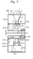
- An optical collecting unit 32 positioned above the light collecting lens 3a has an optical receiving port 32a, the diameter of which is 1.5 to 3 times larger than that of the optical projecting port 25.
- a light transmitting mask 34 having a central slit is arranged at the uppermost position of the optical receiving port 32a. The provision of the mask 34 having a central slit is effective for improving the resolution performance of the thickness measurement.
- the light transmitting mask 34 is made of, for example, a polyester film.
- a partition 202 is arranged for providing thermal separation between the light source 1 and the measuring unit of the reference film S.
- a partition 302 is arranged for thermally isolating the optical receiving unit 33 from the measuring unit of the measured film P.
- air having a predetermined temperature and predetermined humidity is supplied under a predetermined pressure by means of appropriate air conduit. Therefore, the insides of both the upper and lower heads 200 and 300 are always kept at a predetermined temperature and humidity level. As a result, stable thickness measurement is ensured.
- Air-curtain units 110a and 110b shown in Fig. 7 have air injection ports 111 through which controlled temperature and humidity air streams are injected toward the measured film P running in the direction of the arrow B. That is to say, the injected streams of air form air curtains extending in the direction of the width of the measured film P at the entrance of the film P from the outside into the apparatus. This air curtains are effective for interrupting the stream of air produced by the running of the measured film P before the measured film P reaches the measuring stage of the apparatus. Thus, only a limited amount of temperature and humidity controlled air follows the measured film P. This further ensures stable thickness measurement of the measured film P.
- Reference numerals 203, 303, and 304 designate mounting elements attached to reference surfaces 201a and 301a of the upper and lower heads 200 and 300. The provision of such mounting elements enables assembly of all optical and electric elements in such a manner that correct optical relationship among all systems and elements are established.
Landscapes
- Physics & Mathematics (AREA)
- General Physics & Mathematics (AREA)
- Length Measuring Devices By Optical Means (AREA)
Claims (8)
Applications Claiming Priority (2)
| Application Number | Priority Date | Filing Date | Title |
|---|---|---|---|
| JP56201506A JPS58103604A (ja) | 1981-12-16 | 1981-12-16 | フイルムの厚さ測定方法及び測定装置 |
| JP201506/81 | 1981-12-16 |
Publications (3)
| Publication Number | Publication Date |
|---|---|
| EP0082007A2 EP0082007A2 (de) | 1983-06-22 |
| EP0082007A3 EP0082007A3 (en) | 1985-12-18 |
| EP0082007B1 true EP0082007B1 (de) | 1989-07-19 |
Family
ID=16442174
Family Applications (1)
| Application Number | Title | Priority Date | Filing Date |
|---|---|---|---|
| EP82306642A Expired EP0082007B1 (de) | 1981-12-16 | 1982-12-13 | Vorrichtung zum Messen der Dicke eines Films |
Country Status (4)
| Country | Link |
|---|---|
| US (1) | US4623254A (de) |
| EP (1) | EP0082007B1 (de) |
| JP (1) | JPS58103604A (de) |
| DE (1) | DE3279825D1 (de) |
Families Citing this family (14)
| Publication number | Priority date | Publication date | Assignee | Title |
|---|---|---|---|---|
| DE3505810A1 (de) * | 1985-02-20 | 1986-08-21 | Licentia Patent-Verwaltungs-Gmbh, 6000 Frankfurt | Anordnung zur ermittlung der verstellung bzw. einstellung eines weges oder winkels |
| US4778251A (en) * | 1987-03-09 | 1988-10-18 | Rockwell International Corporation | Thickness error compensation for digital gradient-index optical coatings |
| JPS6428509A (en) * | 1987-07-23 | 1989-01-31 | Nippon Kokan Kk | Apparatus for measuring thickness of film |
| JPH01237404A (ja) * | 1987-11-05 | 1989-09-21 | Ryowa Denshi Kk | 膜厚測定方法および装置 |
| JPH0224502A (ja) * | 1988-07-12 | 1990-01-26 | Dainippon Screen Mfg Co Ltd | 膜厚測定方法 |
| US5115417A (en) * | 1989-02-28 | 1992-05-19 | Saunders Alan J | Tide calculating and display device |
| US5396332A (en) * | 1993-02-08 | 1995-03-07 | Ciszek; Theodoer F. | Apparatus and method for measuring the thickness of a semiconductor wafer |
| US5506407A (en) * | 1993-12-21 | 1996-04-09 | Minnesota Mining & Manufacturing Company | High resolution high speed film measuring apparatus and method |
| DE19847617C2 (de) * | 1998-10-15 | 2002-11-07 | Sensor Instr Gmbh | Verfahren und Vorrichtung zum Messen der Länge des Lichtleiters |
| US6762838B2 (en) * | 2001-07-02 | 2004-07-13 | Tevet Process Control Technologies Ltd. | Method and apparatus for production line screening |
| JP2003042967A (ja) * | 2001-07-27 | 2003-02-13 | Hitachi Ltd | パターン欠陥検査装置 |
| CN103175478B (zh) * | 2013-03-08 | 2016-01-20 | 华中科技大学 | 一种基于红外成像的薄膜测厚仪 |
| JP6368408B1 (ja) * | 2017-08-08 | 2018-08-01 | Ckd株式会社 | ブリスタ包装機 |
| JP6568245B2 (ja) * | 2018-01-24 | 2019-08-28 | Ckd株式会社 | 検査装置、ptp包装機、及び、検査装置の較正方法 |
Family Cites Families (16)
| Publication number | Priority date | Publication date | Assignee | Title |
|---|---|---|---|---|
| US2549402A (en) * | 1948-04-01 | 1951-04-17 | Jr Carl A Vossberg | X-ray measuring system |
| US2517330A (en) * | 1949-09-07 | 1950-08-01 | Johns Manville | Apparatus for measuring the thickness of semiopaque material |
| BE620045A (de) * | 1961-07-11 | |||
| US3347130A (en) * | 1962-05-02 | 1967-10-17 | Boeing Co | Optical measuring instruments |
| FR2082717A5 (de) * | 1970-03-25 | 1971-12-10 | Cellophane Sa | |
| DE2117990B2 (de) * | 1971-04-14 | 1973-05-30 | Wsesojusnij nautschno lssledowateP sky i projektno konstruktorskij insti tut metallurgitscheskowo maschinostro jenija, Moskau | Photoelektrisches messgeraet zur beruehrungslosen bestimmung der abmessungen von warmwalzgut |
| US3807876A (en) * | 1972-03-15 | 1974-04-30 | Mitsubishi Electric Corp | Gas densitometer |
| US3761724A (en) * | 1972-07-06 | 1973-09-25 | Resalab Inc | Double beam hydrocarbon gas detector |
| JPS5134754A (ja) * | 1974-09-18 | 1976-03-24 | Oki Electric Ind Co Ltd | Setsuchakuzainoatsusakenshutsusochi |
| JPS583073Y2 (ja) * | 1975-07-19 | 1983-01-19 | 株式会社島津製作所 | ブンコウコウドケイ |
| JPS52153468A (en) * | 1976-06-15 | 1977-12-20 | Fujitsu Ltd | Thickness measuring method of substrates |
| US4085326A (en) * | 1976-10-19 | 1978-04-18 | Industrial Nucleonics Corporation | Radiation reflection method and apparatus particularly for gauging materials exhibiting broadband absorption or scattering, or similar effects |
| DE2655261A1 (de) * | 1976-12-07 | 1978-06-15 | Lippke Gmbh Co Kg Paul | Verfahren und einrichtung zum erzielen einer vorbestimmten dicke extrudierter und anschliessend gereckter folien aus kunststoff, z.b. polypropylen |
| JPS5937767B2 (ja) * | 1977-04-20 | 1984-09-12 | オリンパス光学工業株式会社 | 測光装置 |
| FI782773A7 (fi) * | 1978-09-11 | 1980-03-12 | G W Sohlberg Oy | Foerfarande och anordning foer maetning av vaeggtjockleken hos ett plastfoeremaol |
| GB2077426B (en) * | 1980-05-30 | 1983-12-14 | Fuji Electric Co Ltd | Apparatus for measuring film thickness |
-
1981
- 1981-12-16 JP JP56201506A patent/JPS58103604A/ja active Pending
-
1982
- 1982-12-13 EP EP82306642A patent/EP0082007B1/de not_active Expired
- 1982-12-13 DE DE8282306642T patent/DE3279825D1/de not_active Expired
- 1982-12-14 US US06/449,580 patent/US4623254A/en not_active Expired - Lifetime
Also Published As
| Publication number | Publication date |
|---|---|
| US4623254A (en) | 1986-11-18 |
| EP0082007A3 (en) | 1985-12-18 |
| JPS58103604A (ja) | 1983-06-20 |
| DE3279825D1 (en) | 1989-08-24 |
| EP0082007A2 (de) | 1983-06-22 |
Similar Documents
| Publication | Publication Date | Title |
|---|---|---|
| EP0082007B1 (de) | Vorrichtung zum Messen der Dicke eines Films | |
| US4254337A (en) | Infrared interference type film thickness measuring method and instrument therefor | |
| US4999014A (en) | Method and apparatus for measuring thickness of thin films | |
| CA2136886C (en) | Apparatus, system and method for real-time wafer temperature measurement based on light scattering | |
| US5064280A (en) | Method of measuring the velocity and/or length of endless webs of textile material and apparatus for carrying out the method | |
| JP2004504590A (ja) | コンパクトな分光エリプソメータ | |
| US5642196A (en) | Method and apparatus for measuring the thickness of a film using low coherence reflectometry | |
| US3645623A (en) | Apparatus for monitoring film thickness by reflecting a light beam from the film surface | |
| JPS61189440A (ja) | プラズマ物性測定装置 | |
| CA1195858A (en) | Method of and apparatus for measuring the thickness and the refractive index of transparent materials | |
| US4750834A (en) | Interferometer including stationary, electrically alterable optical masking device | |
| US5646734A (en) | Method and apparatus for independently measuring the thickness and index of refraction of films using low coherence reflectometry | |
| JP2732849B2 (ja) | 干渉測長器 | |
| GB1404944A (en) | Apparatus for the production of a measurement signal or a measurement and control signal | |
| JPH0634318A (ja) | 干渉計測装置 | |
| EP0176826A2 (de) | Verfahren und Vorrichtung für spektrale Zweistrahldurchlässigkeitsmessungen | |
| EP1017995A1 (de) | Verfahren und vorrichtung zur messung der eigenschaften von papier | |
| JP2004138499A (ja) | ガス濃度検出センサ | |
| JPH0118371B2 (de) | ||
| US5659393A (en) | Method of and device for measuring the refractive index of wafers of vitreous material | |
| JPH0327854B2 (de) | ||
| US4577966A (en) | Spectrophotometer | |
| JPH05500853A (ja) | ガラス管壁の厚さを決定するための方法及び装置 | |
| EP0204090B1 (de) | Spektrophotometer | |
| US5170224A (en) | Laser wavelength measuring device |
Legal Events
| Date | Code | Title | Description |
|---|---|---|---|
| PUAI | Public reference made under article 153(3) epc to a published international application that has entered the european phase |
Free format text: ORIGINAL CODE: 0009012 |
|
| 17P | Request for examination filed |
Effective date: 19830202 |
|
| AK | Designated contracting states |
Kind code of ref document: A2 Designated state(s): DE FR GB |
|
| PUAL | Search report despatched |
Free format text: ORIGINAL CODE: 0009013 |
|
| AK | Designated contracting states |
Kind code of ref document: A3 Designated state(s): DE FR GB |
|
| 17Q | First examination report despatched |
Effective date: 19870513 |
|
| GRAA | (expected) grant |
Free format text: ORIGINAL CODE: 0009210 |
|
| AK | Designated contracting states |
Kind code of ref document: B1 Designated state(s): DE FR GB |
|
| REF | Corresponds to: |
Ref document number: 3279825 Country of ref document: DE Date of ref document: 19890824 |
|
| ET | Fr: translation filed | ||
| PLBE | No opposition filed within time limit |
Free format text: ORIGINAL CODE: 0009261 |
|
| STAA | Information on the status of an ep patent application or granted ep patent |
Free format text: STATUS: NO OPPOSITION FILED WITHIN TIME LIMIT |
|
| 26N | No opposition filed | ||
| PGFP | Annual fee paid to national office [announced via postgrant information from national office to epo] |
Ref country code: FR Payment date: 19970917 Year of fee payment: 16 |
|
| PGFP | Annual fee paid to national office [announced via postgrant information from national office to epo] |
Ref country code: GB Payment date: 19970925 Year of fee payment: 16 |
|
| PGFP | Annual fee paid to national office [announced via postgrant information from national office to epo] |
Ref country code: DE Payment date: 19971231 Year of fee payment: 16 |
|
| PG25 | Lapsed in a contracting state [announced via postgrant information from national office to epo] |
Ref country code: GB Free format text: LAPSE BECAUSE OF NON-PAYMENT OF DUE FEES Effective date: 19981213 |
|
| GBPC | Gb: european patent ceased through non-payment of renewal fee |
Effective date: 19981213 |
|
| PG25 | Lapsed in a contracting state [announced via postgrant information from national office to epo] |
Ref country code: FR Free format text: LAPSE BECAUSE OF NON-PAYMENT OF DUE FEES Effective date: 19990831 |
|
| REG | Reference to a national code |
Ref country code: FR Ref legal event code: ST |
|
| PG25 | Lapsed in a contracting state [announced via postgrant information from national office to epo] |
Ref country code: DE Free format text: LAPSE BECAUSE OF NON-PAYMENT OF DUE FEES Effective date: 19991001 |