EP0080568B1 - Support for a group of drawing rollers - Google Patents
Support for a group of drawing rollers Download PDFInfo
- Publication number
- EP0080568B1 EP0080568B1 EP82108294A EP82108294A EP0080568B1 EP 0080568 B1 EP0080568 B1 EP 0080568B1 EP 82108294 A EP82108294 A EP 82108294A EP 82108294 A EP82108294 A EP 82108294A EP 0080568 B1 EP0080568 B1 EP 0080568B1
- Authority
- EP
- European Patent Office
- Prior art keywords
- roll assembly
- draw roll
- counterweight
- draw
- pressure cylinder
- Prior art date
- Legal status (The legal status is an assumption and is not a legal conclusion. Google has not performed a legal analysis and makes no representation as to the accuracy of the status listed.)
- Expired
Links
Images


Classifications
-
- D—TEXTILES; PAPER
- D01—NATURAL OR MAN-MADE THREADS OR FIBRES; SPINNING
- D01D—MECHANICAL METHODS OR APPARATUS IN THE MANUFACTURE OF ARTIFICIAL FILAMENTS, THREADS, FIBRES, BRISTLES OR RIBBONS
- D01D13/00—Complete machines for producing artificial threads
- D01D13/02—Elements of machines in combination
-
- D—TEXTILES; PAPER
- D01—NATURAL OR MAN-MADE THREADS OR FIBRES; SPINNING
- D01H—SPINNING OR TWISTING
- D01H5/00—Drafting machines or arrangements ; Threading of roving into drafting machine
- D01H5/18—Drafting machines or arrangements without fallers or like pinned bars
- D01H5/56—Supports for drafting elements
Landscapes
- Engineering & Computer Science (AREA)
- Mechanical Engineering (AREA)
- Textile Engineering (AREA)
- Yarns And Mechanical Finishing Of Yarns Or Ropes (AREA)
- Spinning Methods And Devices For Manufacturing Artificial Fibers (AREA)
- Forwarding And Storing Of Filamentary Material (AREA)
- Guides For Winding Or Rewinding, Or Guides For Filamentary Materials (AREA)
- Spinning Or Twisting Of Yarns (AREA)
Description
Die Erfindung bezieht sich auf eine Vorrichtung zur Aufnahme eines Streckrollenaggregates in einer Streckspul- oder Spinnstreckspulmaschine.The invention relates to a device for receiving a draw roll assembly in a draw or spin-draw winder.
Um zu verstreckende Multifilamente auf dazu vorgesehene Streckrollenaggregate aufzulegen, respetive letztlich in eine Spuleneinheit einzubringen, werden die Filamente durch manuell geführte sogenannte Saugpistolen übernommen und durch die Bedienungsperson auf die Streckrollenaggregate, respektive in die Aufwindvorrichtung, gebracht. Das von der Saugpistole übernommene Multifilament kann entweder von einem Spinnschacht oder einer Vorlagespule her angeliefert werden. Unter Multifilament soll eine Anzahl zusammengefasster endloser Einzelfibrillen verstanden werden.In order to place multifilaments to be stretched on the intended stretch reel units, or to finally bring them into a spool unit, the filaments are taken over by manually operated so-called suction pistols and brought onto the stretch reel units or into the winding device by the operator. The multifilament taken over by the suction gun can be delivered either from a spinning shaft or a supply spool. Multifilament is to be understood as a number of summarized endless individual fibrils.
Sind die Streckrollenaggregate in Höhen über dem Boden angebracht, die ein Auflegen des Filamentes ohne ein diese Höhe überwindendes Hilfsmittel nicht erlauben, z. B. um die Verteilung mehrerer Multifilamente auf eine Aufwindvorrichtung mit kleinen Ablenkwinkeln oder um eine lange Streckzone zu ermöglichen, so ist es bekannt, dass hierzu mobile Treppen oder Hebebühnen der Bedienungsperson das Auflegen des Filamentes ermöglichen. (z. B. US-A-4 043 718)Are the stretching roller units mounted at heights above the ground that do not allow the filament to be placed without an aid to overcome this height, e.g. B. to allow the distribution of multiple multifilaments on a winding device with small deflection angles or to allow a long stretching zone, it is known that mobile stairs or lifting platforms allow the operator to put on the filament. (e.g. US-A-4 043 718)
Eine solche Arbeitsweise hat jedoch den Nachteil, dass das vorsichtige Führen der Saugpistole und das gleichzeitige Treppensteigen für die Bedienungsperson umständlich ist. Anderseits ist die Verwendung von Hebebühnen relativ teuer. Ausserdem kann bei unsorgfältiger Bedienung der Saugpistole, hauptsächlich beim Auflegen feiner Titer, ein Bruch des Filamentes enstehen, was z. B. eine Wickelbildung an der vorangehenden Galette eines Streckrollenaggregates und entsprechend ein Entfernen des Wickels zur Folge haben kann. Eine weitere Gefahr besteht in der Beschädigung der Streckrollen-Oberflächen durch Saugpistolen.However, such a mode of operation has the disadvantage that the careful operation of the suction gun and the simultaneous climbing of stairs are cumbersome for the operator. On the other hand, the use of lifts is relatively expensive. In addition, if the suction gun is operated improperly, mainly when placing fine titers, a breakage of the filament can occur. B. a winding formation on the preceding godet of a stretching roller unit and correspondingly can have a consequence of removing the winding. Another danger is damage to the surfaces of the stretching rollers by suction pistols.
Der Erfindung liegt deshalb die Aufgabe zugrunde, ein sicheres Auflegen zu ermöglichen, ohne dass die Bedienungsperson die erwähnten Hilfsmittel verwenden muss.The invention is therefore based on the object of making it possible to hang up safely without the operator having to use the aids mentioned.
Die Erfindung, wie sie in den Ansprüchen gekennzeichnet ist, löst die Aufgabe dadurch, dass das Streckrollenaggregat an Schienen geführt ist und diesen Schienen entlang ab einem eine Betriebsposition bestimmenden Anschlag in eine Filamentübernahmeposition verschiebbar ist.The invention, as characterized in the claims, achieves the object in that the stretching roller assembly is guided on rails and can be moved along these rails from a stop determining an operating position into a filament take-over position.
Die durch die Erfindung erreichten Vorteile sind im wesentlichen darin zu sehen, dass die Bedienungsperson ohne Standplatzveränderung alle Streckrollenaggregate und die sich in der Nähe der Aufwindvorrichtung befindlichen Aggregate für das Ansetzen des Filamentes bedienen kann.The advantages achieved by the invention are essentially to be seen in the fact that the operator can operate all of the stretching roller units and the units for attaching the filament in the vicinity of the winding device without changing the position.
Ein weiterer Vorteil besteht in der Möglichkeit, die Verschiebegeschwindigkeit des Streckrollenaggregates durch Mittel zu steuern, so dass Fadenbrüche vermieden werden können.Another advantage is the possibility of controlling the displacement speed of the stretching roller unit by means so that thread breaks can be avoided.
Im folgenden wird die Erfindung anhand von lediglich einen Ausführungsweg darstellenden Zeichnungen näher erläutert.The invention is explained in more detail below with the aid of drawings which illustrate only one embodiment.
Es zeigt:
- Fig. 1 eine Frontansicht der erfindungsgemässen Vorrichtung, halbschematisch dargestellt,
- Fig. 2 eine Seitenansicht der Vorrichtung von Fig. 1, halbschematisch dargestellt,
- Fig. 3 ein Grundriss der Vorrichtung von Fig. 1, halbschematisch dargestellt,
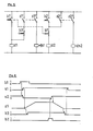
- Fig. 4 + je ein Schema der Steuerung zur Vorrrichtung von Fig. 1,
- Fig. 6 ein Funktionsdiagramm der Steuerung von Fig. 4 und 5.
- 1 is a front view of the device according to the invention, shown semi-schematically,
- 2 is a side view of the device of FIG. 1, shown semi-schematically,
- 3 is a plan view of the device of FIG. 1, shown semi-schematically,
- 4 + each a schematic of the control for the device of FIG. 1,
- 6 is a functional diagram of the controller of FIGS. 4 and 5.
In einer Streckspul- oder Spinnstreckspulmaschine 1 wird ein von einer Vorlagespule oder einem Spinnschacht (beides nicht gezeigt) herkommendes aus vier einzelnen Multifilamenten zusammengefasstes Multifilamentbündel 2 über ein erstes Streckrollenaggregat 3 und anschliessend über ein zweites Streckrollenaggregat 4 in eine Aufspuleinheit 5 geführt. Die Streckrollenaggregate 3 und 4 umfassen je eine an sich bekannte Galette 6, respektive 6', und dazu je eine an sich bekannte Umlenkrolle 7, respektive 7', an welcher jedes Multifilament einzeln in an sich bekannter Weise geführt ist.A
Das erste Streckrollenaggregat 3 ist an einem Tragrahmen 8 fest angeordnet, während das zweite Streckrollenaggregat 4 an zwei Führungsstangen 9 in im wesentlichen vertikaler Richtung verschiebbar geführt ist.The first
Die Führungsstangen 9 sind mit ihrem unteren Ende auf einer zum Tragrahmen 8 gehörenden Tragplatte 10 abgestützt, mit dieser verbunden und an ihrem oberen Ende durch eine Deckplatte 11 fixiert. Die Deckplatte 11 ist ihrerseits durch Träger 12, die ebenfalls auf der Tragplatte 10 abgestützt und mit ihr verbunden sind, abgestützt und fixiert.The lower end of the
Über Rollen 13 und 14 wird ein Seil 15 geführt, welches mit dem einen Ende am zweiten Streckrollenaggregat 4 und mit dem anderen Ende an einem Gegengewicht 16 befestigt ist. Die Rolle 13 ist mittels einem Lager 17, und die Rolle 14 mittels einem Lager 18 drehbar auf der Deckplatte 11 fest angeordnet.A
Das Gegengewicht 16 ist mittels daran befestigter Gleitelemente 19, die an Schienen 20 anliegen, durch diese geführt. Die Schienen 20 stützen sich mit ihrem unteren Ende auf der Tragplatte 10 ab und sind an dieser befestigt. An ihrem oberen Ende sind die Schienen 20 durch die Deckplatte 11 fixiert.The
An der unteren Stirnseite des Gegengewichtes 16 ist ausserdem ein daran befestigtes Joch 16' vorgesehen, welches über die Breite B des Gegengewichtes 16 hinausragt, und mit zwei Druckzylindern 21 verbunden ist. Die Druckzylinder ihrerseits sind mittels Stützen 22 mit der Deckplatte 11 verbunden.On the lower end face of the
Verstrebungen 23 und 24 (nur in Fig. 2 gezeigt), die am Tragrahmen 8, respektive an den Trägern 12 befestigt sind, fixieren die Spinnstreckspulmaschine 1 entweder an einer Wand (nicht gezeigt) oder an einer weiteren Tragkonstruktion (nicht gezeigt).
In der Betriebsposition liegt das zweite Streckrollenaggregat 4 an Anschlägen 25 an, die an der Unterseite der Deckplatte 11 befestigt sind.In the operating position, the second
Die Betätigung der Zylinder 21 ist mit den Schemata der Figuren 4 und 5 und mit dem Funktionsdiagramm der Fig. 6 dargestellt. Es werden dazu folgende Elemente benötigt:The actuation of the
Eine Druckluftquelle 26 speist via eine Druckluftleitung 27, in der ein Druckreduzierventil 28 eingebaut ist, eine Druckluftleitung 29, resp. 29', zur Speisung der Zylinder 21 für die Aufwärtsbewegung des Gegengewichtes 16 sowie eine Druckluftleitung 30, resp. 30', zur Speisung der Zylinder 21 für die Abwärtsbewegung des Gegengewichtes 16.A
In den Leitungen 29 und 30 ist je ein elektropneumatisch gesteuertes 3/2-Weg Pneumatikventil 31, resp. 32, mit sogenannter Sperr-Null-Stellung, sowie je ein verstellbares Drossel-Rückschlagventil 33, resp. 34, vorgesehen. Diese letztgenannten Ventile sind derart eingebaut, dass die Entlüftung der Leitungen 29', resp. 30', gedrosselt ist.In the
Im weiteren benötigt die Steuerung je einen elektrischen Impulsdruckknopfschalter b1 und b2 sowie einen Endschalter b3 der die untere Endlage des Gegengewichtes 16 signalisiert.Furthermore, the control system requires an electrical pulse pushbutton switch b1 and b2 and a limit switch b3 which signals the lower end position of the
Die Steuerung funktioniert folgendermassen:The control works as follows:
In Betriebsposition des Streckrollenaggregates 4, d.h. in der Ausgangslage der Steuerung, liegt das Streckrollenaggregat 4 in der oberen Endlage an den Anschlägen 25, d.h. das Gegengewicht 16 ist in der unteren, in den Figuren 1, 2 und 4 gezeigten Lage.In the operating position of the
In dieser Ausgangsstellung der Steuerung ist ein Relais d2 (Fig. 5) aktiviert, die dazugehörigen Relaiskontakte d2' und d2" geschlossen, und die Magnetspule s2 des Ventiles 32 aktiviert und dadurch das Ventil 32 in Durchlaßstellung, so dass die Zylinder 21 via Druckleitung 30' mit Druckluft beaufschlagt sind. Gleichzeitig ist die Druckleitung 29' via das sich in Durchlaßstellung (Fig. 4) befindliche Ventil 31 entlüftet, so dass die Zylinder 21 kolbenstangenseitig nicht mit Druckluft beaufschlagt sind.In this starting position of the control system, a relay d2 (FIG. 5) is activated, the associated relay contacts d2 'and d2 "are closed, and the solenoid coil s2 of the
Soll nun nach einem Fadenbruch oder beim Neuauflegen eines Multifilamentes, resp. Multifilamentbündels, das Streckrollenaggregat 4 in die untere Endlage, d.h. bis zur Auflage auf die Tragplatte 10, gebracht werden, so wird der Impulsschalter b1 (Fig. 4) manuell betätigt, so dass die Schaltkontakte b1' (Fig. 5) geschlossen und die Schaltkontakte b1" geöffnet werden. Dadurch wird einerseits das Relais d2 stromlos und die Relaiskontakte d2' und d2" geöffnet, die Magnetspule s2 stromlos, und dadurch das Ventil 32 in die Null-Sperrstellung gebracht, sowie anderseits ein Relais d1 aktiviert, und dadurch die Relaiskontakte d1' und dl" geschlossen, wodurch die Magnetspule s1 des Ventiles 31 aktiviert wird und dadurch das Ventil 31 aus der Sperrstellung in die Durchlaßstellung verschoben wird. Durch diese Massnahme wird einerseits die Druckleitung 30' entlüftet und anderseits die Druckleitung 29' und damit die Zylinder 21 kolbenstangenseitig mit Druckluft beaufschlagt. Die Zylinder 21 schieben nun das Gewicht mit einer mittels dem Ventil 34 gedrosselten Geschwindigkeit nach oben.Should now after a thread break or when re-laying a multifilament, resp. Multifilament bundle, the
Bei dieser Aufwärtsbewegung wurden die Schaltkontakte b3' geschlossen, so dass der geschlossene Relaiskontakt d1' die Selbsthaltefunktion für das Relais d1 erfüllen kann.During this upward movement, the switching contacts b3 'were closed, so that the closed relay contact d1' can perform the self-holding function for the relay d1.
Nach dem Auflegen des Multifilamentbündels auf die Galetten, respektive Umlenkrollen der Streckrollenaggregate 3 und 4, dem Einfädeln in einen am Streckrollenaggregat 4 fest angeordneten Fadenführer 35 (Fig. 1) sowie dem Einführen in die Aufspuleinheit 5, betätigt die Bedienungsperson den Impulsschalter b2. Dadurch wird das Relais d2 aktiviert und die Relaiskontakte d2' und d2" geschlossen, wodurch die Selbsthaltefunktion für das Relais d2 erfüllt ist und die Magnetspule s2 des Ventiles 32 aktiviert, d.h. das Ventil 32 aus der Sperr-Null-Stellung in die Durchlass-Stellung verschoben wird. Die Zylinder 21 werden dadurch via Leitung 30' mit Druckluft beaufschlagt.After placing the multifilament bundle on the godets or deflection rollers of the
Die Kolben 21' der Zylinder 21 sind nun beidseitig mit demselben Luftdruck beaufschlagt. Die Kolbenkraft ist kolbenstangenseitig jedoch entsprechend dem Kolbenstangenquerschnitt kleiner als auf der Gegenseite, so dass die für die Abwärtsbewegung des Gewichtes 16 zur Verfügung stehende Kraft Pabw der Differenz zwischen der Summe der Gewichtskraft PG und der abwärts gerichteten Kolbenkraft P2 und der aufwärtsgerichteten Kolbenkraft P1 entspricht (Pabw = P2 + PG - P1)' Die Abwärtsbewegung des Gewichtes 16 ist deshalb mittels Ventil 33 in ihrer Geschwindigkeit gedrosselt.The pistons 21 'of the
Hat das Streckrollenaggregat 4 die obere Endlage, d.h. die Anlage an den Anschlägen 25 erreicht, so wird vom Joch 16' der Endschalter b3 betätigt, wodurch das Relais d1 stromlos und damit einerseits die durch den Relaiskontakt d1' gegebene Selbsthaltefunktion für das Relais d1 unterbrochen, sowie durch das Öffnen des Relaiskontaktes d1" das Ventil 31 wieder zurück in die Sperr-Null-Stellung verschoben wird. In dieser Stellung dieses Ventiles ist die Druckleitung 29' entlüftet und die Kolbenstangenseite des Zylinders 21 entlastet.If the
Die Steuerung hat ihre Ausgangsstellung damit wieder erreicht.The control has now returned to its starting position.
Das Streckrollenaggregat 4 wird nun mit der Gewichtskraft PG plus der Kolbenkraft P2 gegen die Anschläge 25 gepresst.The stretching
Der erwähnte Steuerungsablauf ist im weiteren mit dem Funktionsdiagramm der Figur 6 dargestellt. Dabei bedeutet 1 = EIN und 0 = AUS. Im weiteren weisen die Bezeichnungen auf die bisher erwähnten Elemente der Steuerung hin.The control sequence mentioned is shown below with the functional diagram of FIG. 6. 1 = ON and 0 = OFF. In addition, the designations have the control elements mentioned so far.
Im weiteren ist das zweite Streckrollenaggregat 4 mit einem daran befestigten Wärmeschutzkasten 36 abgedeckt, der an seiner oberen, die Galette 6 überdeckenden Wand einen Anschlußschacht 37 aufweist, in den, in der Betriebsposition des Streckrollenaggregates 4 eine Dampfabsaugdüse 38 dicht hinein mündet.Furthermore, the second
Um diese Dichtigkeit zu erhalten, ist die Dampfabsaugdüse 38 derart mittels einer federnden Stütze 39 an der Deckplatte 11 befestigt, dass in der Betriebsposition des Streckrollenaggregates 4 die Dampfabsaugdüse 38 mit der Kraft der gespannten Stütze 39 an den inneren Schachträndern (nicht besonders gekennzeichnet) des Anschlußschachtes 37 dicht anliegt.In order to maintain this tightness, the
Die Dampfabsaugdüse ist ihrerseits an ein Dampfabsaugrohr 40 angeschlossen, welches in an sich bekannter Weise mit einem flexiblen Rohrteil (nicht gezeigt) versehen ist, damit die Dampfabsaugdüse der Bewegung der federnden Stütze 39 folgen kann.The steam suction nozzle is in turn connected to a
Claims (8)
Applications Claiming Priority (2)
| Application Number | Priority Date | Filing Date | Title |
|---|---|---|---|
| CH691381 | 1981-10-29 | ||
| CH6913/81 | 1981-10-29 |
Publications (3)
| Publication Number | Publication Date |
|---|---|
| EP0080568A2 EP0080568A2 (en) | 1983-06-08 |
| EP0080568A3 EP0080568A3 (en) | 1986-03-12 |
| EP0080568B1 true EP0080568B1 (en) | 1988-03-16 |
Family
ID=4317014
Family Applications (1)
| Application Number | Title | Priority Date | Filing Date |
|---|---|---|---|
| EP82108294A Expired EP0080568B1 (en) | 1981-10-29 | 1982-09-09 | Support for a group of drawing rollers |
Country Status (7)
| Country | Link |
|---|---|
| US (1) | US4535515A (en) |
| EP (1) | EP0080568B1 (en) |
| JP (1) | JPS5882952A (en) |
| DD (1) | DD208634A5 (en) |
| DE (1) | DE3278244D1 (en) |
| IE (1) | IE53964B1 (en) |
| IN (1) | IN156559B (en) |
Families Citing this family (5)
| Publication number | Priority date | Publication date | Assignee | Title |
|---|---|---|---|---|
| EP0080568B1 (en) * | 1981-10-29 | 1988-03-16 | Maschinenfabrik Rieter Ag | Support for a group of drawing rollers |
| JPH0475441A (en) * | 1990-07-17 | 1992-03-10 | Toshiba Corp | Rotor wedge of electric rotating machine |
| WO1996009425A1 (en) * | 1994-09-21 | 1996-03-28 | Maschinenfabrik Rieter Ag | Spinning winding frame |
| JP5864338B2 (en) * | 2012-03-30 | 2016-02-17 | Tmtマシナリー株式会社 | Spinning and winding device and spinning and winding equipment |
| CN103205820B (en) * | 2013-03-22 | 2015-08-05 | 桐昆集团股份有限公司 | The disc guiding device of lifting head is convenient in manufacture of PET fiber filament |
Family Cites Families (12)
| Publication number | Priority date | Publication date | Assignee | Title |
|---|---|---|---|---|
| CA640867A (en) * | 1962-05-08 | S. Goy Ronald | Hot stretching of fibres | |
| US2900220A (en) * | 1954-01-08 | 1959-08-18 | Shaw Gilbert | Process for melt spinning and orienting polystyrene filaments |
| NL285919A (en) * | 1961-11-24 | |||
| CH463340A (en) * | 1968-03-20 | 1968-09-30 | Barmag Barmer Maschf | Clip-on gate for pay-off spools |
| US3817061A (en) * | 1970-11-12 | 1974-06-18 | Monsanto Co | Heated roll deposit cleaning apparatus |
| DE2339166A1 (en) * | 1973-08-02 | 1975-02-13 | Zinser Textilmaschinen Gmbh | DEVICE FOR TREATING A PARTICULARLY SYNTHETIC THREAD |
| US4043718A (en) * | 1974-10-03 | 1977-08-23 | Teijin Limited | Spinning apparatus with retractable suction gun |
| JPS6032041Y2 (en) * | 1978-11-07 | 1985-09-25 | 帝人株式会社 | Yarn processing roller |
| DE3069729D1 (en) * | 1979-02-08 | 1985-01-17 | Ici Plc | Automatic bobbin changing on thread winding machines |
| US4311285A (en) * | 1980-07-07 | 1982-01-19 | Allied Corporation | Yarn winding method and apparatus to maintain tension during tail formation |
| US4421282A (en) * | 1981-07-27 | 1983-12-20 | Owens-Corning Fiberglas Corporation | Apparatus for forming and packaging multistrand roving |
| EP0080568B1 (en) * | 1981-10-29 | 1988-03-16 | Maschinenfabrik Rieter Ag | Support for a group of drawing rollers |
-
1982
- 1982-09-09 EP EP82108294A patent/EP0080568B1/en not_active Expired
- 1982-09-09 DE DE8282108294T patent/DE3278244D1/en not_active Expired
- 1982-09-24 IN IN1104/CAL/82A patent/IN156559B/en unknown
- 1982-10-18 IE IE2522/82A patent/IE53964B1/en unknown
- 1982-10-25 US US06/436,388 patent/US4535515A/en not_active Expired - Fee Related
- 1982-10-28 DD DD82244344A patent/DD208634A5/en not_active IP Right Cessation
- 1982-10-29 JP JP57189350A patent/JPS5882952A/en active Granted
Also Published As
| Publication number | Publication date |
|---|---|
| EP0080568A3 (en) | 1986-03-12 |
| IN156559B (en) | 1985-09-07 |
| IE822522L (en) | 1983-04-29 |
| DE3278244D1 (en) | 1988-04-21 |
| JPH0312030B2 (en) | 1991-02-19 |
| EP0080568A2 (en) | 1983-06-08 |
| IE53964B1 (en) | 1989-04-26 |
| US4535515A (en) | 1985-08-20 |
| DD208634A5 (en) | 1984-04-04 |
| JPS5882952A (en) | 1983-05-18 |
Similar Documents
| Publication | Publication Date | Title |
|---|---|---|
| DE657571C (en) | Stopping and reporting device for spinning and other textile machines | |
| DE4121775A1 (en) | RINSING DEVICE WITH A CONTROL DEVICE FOR CONTROLLING THE PRESSURE PRESSURE OF A COIL ON A DRIVE ROLLER | |
| DE3325422A1 (en) | LOADING DEVICE FOR STRETCHERS | |
| DE19548840A1 (en) | Easily serviced mechanism in a sliver doubling and drafting engine | |
| EP0080568B1 (en) | Support for a group of drawing rollers | |
| DE2912777A1 (en) | WINDING DEVICE WITH CAN CHANGER FOR STORING FIBER BAND IN SPINNING CANS | |
| CH683697A5 (en) | Apparatus for automatically applying or piecing a yarn and method for its operation. | |
| EP0806504B1 (en) | Centralized control device for thread clamps of creels | |
| EP2674519B1 (en) | Textile machine with a large number of work positions | |
| CH645684A5 (en) | METHOD AND DEVICE FOR EXTENDING THE THREAD SHEET FEEDED IN A TUFTING MACHINE. | |
| DE2802805A1 (en) | DEVICE FOR FITTING AND REMOVING SPOOLS IN SPINNING MACHINES | |
| DE2832930A1 (en) | DEVICE FOR SWITCHING OFF AND SWITCHING ON A WORKSTATION OF A TEXTILE MACHINE | |
| DE2327164A1 (en) | WINDING DEVICE FOR WINDING TEXTILE FEDS | |
| EP0829562B1 (en) | Texturizing machine with a height-adjustable yarn feed-guide | |
| EP0309700B1 (en) | Gripper loom | |
| WO1994009197A1 (en) | Device for controlling a yarn on a textile machine | |
| DE2434718A1 (en) | RING BANK FOLLOW-UP DEVICE FOR RING SPINNING MACHINES | |
| EP0824071B1 (en) | Device for seizing a broken printing web | |
| EP0441178A1 (en) | Apron drafting machine and spinning machine with a plurality of such apron drafting machines | |
| EP0013368B1 (en) | Device for regulating the tension in a web | |
| DE3604658C2 (en) | ||
| DE19507266C1 (en) | Sliver stop for drafting system on spinning machines | |
| EP0143291A1 (en) | Drawing frame for spinning machines | |
| DE19641160A1 (en) | Upper rollers for comber detaching and delivery roller pairs | |
| DE2749797A1 (en) | Creel braking system - has pressure source and pressure store with brake sections with defined force lines to prevent flutter |
Legal Events
| Date | Code | Title | Description |
|---|---|---|---|
| PUAI | Public reference made under article 153(3) epc to a published international application that has entered the european phase |
Free format text: ORIGINAL CODE: 0009012 |
|
| AK | Designated contracting states |
Designated state(s): CH DE FR GB IT LI NL |
|
| 17P | Request for examination filed |
Effective date: 19840612 |
|
| PUAL | Search report despatched |
Free format text: ORIGINAL CODE: 0009013 |
|
| AK | Designated contracting states |
Kind code of ref document: A3 Designated state(s): CH DE FR GB IT LI NL |
|
| 17Q | First examination report despatched |
Effective date: 19870605 |
|
| GRAA | (expected) grant |
Free format text: ORIGINAL CODE: 0009210 |
|
| AK | Designated contracting states |
Kind code of ref document: B1 Designated state(s): CH DE FR GB IT LI NL |
|
| REF | Corresponds to: |
Ref document number: 3278244 Country of ref document: DE Date of ref document: 19880421 |
|
| ET | Fr: translation filed | ||
| ITF | It: translation for a ep patent filed |
Owner name: GUZZI E RAVIZZA S.R.L. |
|
| GBT | Gb: translation of ep patent filed (gb section 77(6)(a)/1977) | ||
| R20 | Corrections of a patent specification |
Effective date: 19880601 |
|
| PLBE | No opposition filed within time limit |
Free format text: ORIGINAL CODE: 0009261 |
|
| STAA | Information on the status of an ep patent application or granted ep patent |
Free format text: STATUS: NO OPPOSITION FILED WITHIN TIME LIMIT |
|
| 26N | No opposition filed | ||
| PGFP | Annual fee paid to national office [announced via postgrant information from national office to epo] |
Ref country code: NL Payment date: 19900930 Year of fee payment: 9 |
|
| PG25 | Lapsed in a contracting state [announced via postgrant information from national office to epo] |
Ref country code: NL Effective date: 19920401 |
|
| NLV4 | Nl: lapsed or anulled due to non-payment of the annual fee | ||
| ITTA | It: last paid annual fee | ||
| PGFP | Annual fee paid to national office [announced via postgrant information from national office to epo] |
Ref country code: GB Payment date: 19940815 Year of fee payment: 13 Ref country code: CH Payment date: 19940815 Year of fee payment: 13 |
|
| PGFP | Annual fee paid to national office [announced via postgrant information from national office to epo] |
Ref country code: DE Payment date: 19940817 Year of fee payment: 13 |
|
| PGFP | Annual fee paid to national office [announced via postgrant information from national office to epo] |
Ref country code: FR Payment date: 19940819 Year of fee payment: 13 |
|
| PG25 | Lapsed in a contracting state [announced via postgrant information from national office to epo] |
Ref country code: GB Effective date: 19950909 |
|
| PG25 | Lapsed in a contracting state [announced via postgrant information from national office to epo] |
Ref country code: LI Effective date: 19950930 Ref country code: CH Effective date: 19950930 |
|
| GBPC | Gb: european patent ceased through non-payment of renewal fee |
Effective date: 19950909 |
|
| REG | Reference to a national code |
Ref country code: CH Ref legal event code: PL |
|
| PG25 | Lapsed in a contracting state [announced via postgrant information from national office to epo] |
Ref country code: FR Effective date: 19960531 |
|
| PG25 | Lapsed in a contracting state [announced via postgrant information from national office to epo] |
Ref country code: DE Effective date: 19960601 |
|
| REG | Reference to a national code |
Ref country code: FR Ref legal event code: ST |