EP0080481B1 - Procede et dispositif pour la communication serie asynchrone de type multipoints de plusieurs emetteurs-recepteurs logiques - Google Patents
Procede et dispositif pour la communication serie asynchrone de type multipoints de plusieurs emetteurs-recepteurs logiques Download PDFInfo
- Publication number
- EP0080481B1 EP0080481B1 EP82901720A EP82901720A EP0080481B1 EP 0080481 B1 EP0080481 B1 EP 0080481B1 EP 82901720 A EP82901720 A EP 82901720A EP 82901720 A EP82901720 A EP 82901720A EP 0080481 B1 EP0080481 B1 EP 0080481B1
- Authority
- EP
- European Patent Office
- Prior art keywords
- character
- message
- network
- signal
- transmission
- Prior art date
- Legal status (The legal status is an assumption and is not a legal conclusion. Google has not performed a legal analysis and makes no representation as to the accuracy of the status listed.)
- Expired
Links
Images

Classifications
-
- H—ELECTRICITY
- H04—ELECTRIC COMMUNICATION TECHNIQUE
- H04L—TRANSMISSION OF DIGITAL INFORMATION, e.g. TELEGRAPHIC COMMUNICATION
- H04L12/00—Data switching networks
- H04L12/28—Data switching networks characterised by path configuration, e.g. LAN [Local Area Networks] or WAN [Wide Area Networks]
- H04L12/40—Bus networks
- H04L12/407—Bus networks with decentralised control
- H04L12/413—Bus networks with decentralised control with random access, e.g. carrier-sense multiple-access with collision detection [CSMA-CD]
-
- H—ELECTRICITY
- H04—ELECTRIC COMMUNICATION TECHNIQUE
- H04L—TRANSMISSION OF DIGITAL INFORMATION, e.g. TELEGRAPHIC COMMUNICATION
- H04L12/00—Data switching networks
- H04L12/28—Data switching networks characterised by path configuration, e.g. LAN [Local Area Networks] or WAN [Wide Area Networks]
- H04L12/40—Bus networks
- H04L12/4013—Management of data rate on the bus
Definitions
- the present invention relates to logical communication networks formed by transceiver equipment, and more particularly to networks allowing communication of the multipoint type, that is to say in which each transceiver can communicate with each of the other transceivers. network receivers.
- networks have been developed which allow multipoint communications, in which direct communication from a sender to a recipient can be carried out.
- these devices use the principle of contention, that is to say that each transceiver connected to the network can transmit if no other transmission is in progress.
- the transmission is of the synchronous type, at high speed, with suppression of the carrier wave during the absence of transmission, so that any transceiver s very quickly realizes that the network is free or busy.
- French Patent No. 2306478 describes such a device: a message transmission begins with a bit synchronization signal, and an interruption at any time is interpreted as an end of message, the network lying immediately to the idle state.
- This device can only operate with a code carrying the sender's clock, and the transmission is of the synchronous type.
- the messages contain the addresses of the sender and the recipient. In the event of a collision on the network, the senders stop and resume the transmission after waiting for a random duration, this duration possibly being practically zero. No collision signal is sent over the network.
- European patent application No. 0023105 also describes such a device using the principle of contention, but in which the message is transmitted in a particular code containing packets of eight binary signals. Transmission is synchronous, the message carrying the clock, but no recipient address is sent, so that all receivers are recipients of all messages.
- the particular code obliges to wait at least the duration of a packet before resuming an interrupted transmission.
- British patent application N ⁇ 2013452 describes a device in which the sending equipment designates its successor, the equipment being thus authorized to transmit one after the other in an modifiable order. It is a very different technique from restraint.
- Asynchronous type transmission networks make it possible to make installations at lower speed but much less expensive; detecting network availability is more difficult, so that multipoint connections have never been made using the principle of contention. Indeed, in a transmission in asynchronous mode, the messages are formed of a series of characters separated by intervals during which the carrier wave is suppressed, so that it is insufficient to verify that this carrier wave is absent to know if a message is not being transmitted.
- multipoint links have been produced in which a master device in turn interrogates the secondary equipment to acquire the information that the secondary equipment has to transmit, and directly selects the secondary equipment to which it wants transmit information. This leads to the achievement of relatively complex and rigid hierarchical networks.
- the object of the present invention is in particular to obviate the drawbacks of known networks by proposing a method and a device allowing the transmission of information at medium speed in asynchronous mode between several logical transceivers to produce networks having the following characteristics: low cost compared to synchronous transmission networks; multi-point configuration; direct communication from sender to recipient.
- the network is made up of transceivers each composed of a transmitter circuit and a receiver circuit.
- the transceiver wanting to send a message will be called the sender, the transceiver for whom the message is intended will be called the recipient.
- Another object of the present invention is to provide a method and a device for making networks in which the physical position and the number of transceivers connected to the network can be modified at will.
- Another object of the invention is to allow the creation of networks in which the content of the transported messages can be freely modified.
- Another object of the invention is to produce such networks from known logic circuits which are usually used for point-to-point asynchronous links.
- the device comprises means for carrying out several steps: after reception of a character not intended for it, the equipment awaiting transmission remains tuned for a duration greater than a minimum waiting time predetermined; if, during this waiting period, it has not detected a character, it emits a message start signal; it then transmits the characters of the message, at least one of which designates the address of the recipient and the address of the sender; it finally sends an end of message signal; on each character or signal transmission, the sender compares the signals corresponding to the characters transmitted and the signals detected simultaneously while listening; if the signals are identical, it continues the transmission of the message and, if the signals are different, it interrupts the transmission of the message, transmits on the network an interrupt character, remains listening for a random time greater than minimum waiting time, and resumes transmission.
- this arrangement allows the use of the contention principle for asynchronous communication of the multipoint type of logical messages, these messages being formed of a series of binary signals grouped in coded characters of the same length, separated by interruptions. By respecting the various waiting times, the risks of simultaneous transmissions of several messages by different senders are reduced.
- the start of message, end of message and interruption signals are substantially identical.
- the interrupt characters commonly used in the technique of asynchronous communications are used, so that their recognition by the receiving circuits can be carried out by the conventional circuits usually used for asynchronous point transmissions. medium rare.
- These interrupt characters include a continuous signal of duration greater than the duration of the characters forming the message, so that their form is different from all the codes used in the characters composing the message.
- the network thus produced is independent of the encodings used to encode the characters forming the messages to be transmitted, so that it can support the most diverse applications.
- the predetermined minimum waiting time is at least equal to the transmission time of a character, increased by the maximum internal processing time of a transceiver between the end of transmission of a character and the start of the transmission of the next, and increased the signal propagation time between the extreme points of the network. This ensures that non-reception of a signal during the waiting time means that no message is being transmitted. In addition, if a transmitter circuit breaks down during transmission, the other senders can occupy the network without waiting for an end of message which would only occur after the repair of the defective transmitter circuit.
- the comparison can be carried out at the end of the emission of the character.
- two senders can start a transmission simultaneously, the error being detected only at the end of the first or second character.
- the risks of such a collision phenomenon can be reduced by carrying out this comparison at the end of transmission of each binary signal contained in the character.
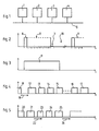
- the method of the present invention allows communication, as shown schematically in FIG. 1, several transceivers on the same network in an asynchronous mode.
- the transmitters 1 to 4 are connected in parallel to the same line 5.
- the line and the connections comprise only one conductor, but it is clear that two conductors are necessary.
- wireless transmission networks can be produced, the transmitters 1 to 4 being connected in parallel by radio waves, or optical links such as infrared or fibers. optical.
- the information transmitted does not carry the clock; this is why the characters are surrounded by a binary signal at the start of a character and a binary signal at the end of a character.
- the recipient uses the binary start of character signal to reset his own clock and his own sampling device on a transition. Sampling is performed at a higher frequency, so that the timing is sufficient for the entire duration of transmission of a character.
- the timing thus achieved is a function essentially different from the synchronization obtained by the binary signals at the start of transmission of the synchronous transmissions.
- FIG. 2 There is shown in FIG. 2 a possible form character, comprising a starting binary signal 6, followed by eight binary signals whose coding makes it possible to designate the character to be transmitted, the last binary signal being followed by a binary signal at the end of character 7.
- the character 8 thus formed is separated from the next character 9 by an interval 10 of essentially variable length.
- the length of this interval 10 depends on the speed of processing of the transmitter circuits between two consecutive characters.
- the length of characters 8 or 9 depends on the number of binary signals forming these characters; generally, five to eight binary signals can be used, more possibly a parity signal.
- Fig. 3 shows, in relation to FIG. 2, an interrupt character 11 whose particularity is to be continuous and of a duration greater than that of a character defined in FIG. 2, forming the message.
- this message comprises a message start signal 12, preferably formed by an interrupt character such as character 11, a second character 13 designating for example the address of the recipient of the message, a third character 14 designating for example the address of the sender, a series of characters 15 to 16 containing the characters of the message itself to be transmitted, and an end of message signal 17, of preferably constituted by an interrupt character such as character 11. All of these signals and characters forming the message are constituted in the manner described in relation to FIG. 2 and are separated by intervals such as interval 10 during which no signal is transmitted on the network.
- the sender Before starting the transmission of a message as shown in fig. 4, the sender must first of all respect a waiting time, represented by the arrow 18, after the last signal 19 detected on the network.
- the waiting time 18 must have a duration greater than a predetermined minimum waiting time. This minimum waiting time is at least equal to the transmission time of a character on the network, increased by the usual internal processing time of a transmitting circuit between the end of transmission of a character and the start of transmission. of the following, and increased the propagation time of the signals between the extreme points of the network.
- the sender compares the signals corresponding to the character being transmitted and the signals detected simultaneously while listening. According to the result of this comparison, if the signals are identical, the sender continues sending the message. On the other hand, if the signals are different, the sender interrupts the transmission of the message, transmits an interrupt character on the network, stays tuned for a waiting period, and starts the transmission again after this listening time.
- the waiting time must be different for each transceiver so that, if several senders are waiting for transmission while a third is in operation, there will not be a systematic collision when resuming transmissions.
- this waiting time always greater than the predetermined minimum waiting time, has a random duration so as not to introduce a hierarchy between the various transceivers.
- This phase of the process makes it possible to avoid, on the one hand, bad transmission of messages and, on the other hand, collisions occurring when several transceivers start a transmission at the same time.
- the first characters of the two messages sent by two collision senders are interrupt characters, so that each of the two senders detects the identity of the characters received on the network and of the characters sent.
- Each of the two senders therefore continues the transmission by issuing the characters designating the address of the recipient.
- the signals present on the network are formed by the combination of the two transmitted signals, and several cases are then possible.
- the mixing of the information can give a reading and / or parity error so that the two senders stop the transmission, emit an interrupt signal and wait for a random delay before resuming this transmission.
- this sender detects the error and sends an interrupt signal, so that all senders stop sending and wait for a random delay before resuming.
- the senders will transmit their own addresses which are necessarily different. In this case, at least one of the senders will detect a difference and produce the interruption.
- the comparison is carried out at the end of transmission of the character.
- these comparisons can be made at the end of transmission of each binary signal contained in the character.
- a first way consists in verifying that no complete character was received during this initial listening phase; in this case, the risk of collision is relatively high, since it is very likely that two senders can start a transmission during the transmission period of a character.
- a second method which consists in verifying, on the one hand, that no character was received during the initial listening phase and that the network is in the idle state when the sender plans to start transmitting. The time during which a collision can occur is thus considerably reduced.
- the method of the present invention also provides a phase for immediately producing an acknowledgment signal sent by the recipient to the sender, so as to occupy the network for a minimum time.
- This acknowledgment message can include a character designating the address of the sender, a character designating the address of the recipient, possibly characters of information, and a final character of interruption.
- the recipient sends the first acknowledgment character before the end of the predetermined minimum waiting time following the interrupt character of the sender signifying the end of the message.
- the recipient is the only one able to send a message before the end of this predetermined minimum waiting time, so that there is no need for him to send an interrupt character at the start of an acknowledgment message, the other senders cannot send before the end of this predetermined minimum waiting time.
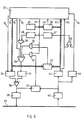
- Fig. 6 shows the main functional elements of a transceiver according to the present invention.
- This transceiver includes a message generation and processing unit 30 comprising several output lines 31 conveying the character to be transmitted to a serialization circuit 36, an output line 32 controlling the transmission of characters between the generation unit 30 and the serialization circuit 36, an output line 33 connected to an input terminal of an AND gate 51 and an AND gate 52 to validate the emission of an interrupt signal 11 in the event of detection of collision during the transmission phase, an output line 34 for controlling the transmission of the end of message signal 17, an output line 35 for controlling the transmission of the start of message signal 12 by an AND gate 58.
- a circuit 37 generating the start of message, end of message and interruption signals in the event of a collision is controlled by an OR gate 53 whose input terminals are connected to line 34 and to the output terminals of AND gates 51, 52 and 58.
- An OR gate 38 is interposed between the output of the serialization circuit 36, the output of the circuit 37 and the input of a line amplifier 39 whose output is connected to the network 40.
- the message generation and processing unit 30 also includes several input lines 57 conveying the character received, an input line 55 controlling the transmission of characters between a deserialization circuit 44 and the processing unit 30, a input line 56 connected to a circuit 43 for detecting the interrupt signal, an input line 54 connected to the output of a comparator circuit 50 intended to compare the character received on lines 57 at the address of the 'transceiver equipment defined by a circuit 49.
- the deserializer circuit 44 and the interrupt signal detection circuit 43 are connected to the output of a line adaptation circuit 42, itself directly connected to the network 40.
- the OR gate 46 detects the reception of a character or an interrupt signal and controls a timer circuit 47 responsible for prohibiting the remission of a new message before a predetermined minimum time.
- the output of this timing circuit 47 controls a random timing generation circuit 48 which will authorize the transmission of the command 35 for transmitting the message start signal to circuit 37 through AND gate 58 and OR gate 53.
- Circuit 41 is used if the comparison between signal transmitted and signal received is carried out after transmission of each binary element composing the characters and during the intervals between each character.
- Circuit 45 is used when the comparison is made after the transmission of each character father.
- the AND gates 51 and 52 validated by the output line 33 of the generation unit, allow the transmission of the collision detection signal to the circuit generating the interrupt signal 37 through the OR gate 53.
- the circuits constituting the transceiver can be produced by electronic means well known to specialists. For this reason, it is unnecessary to describe in detail the construction of these circuits.
- the realization of these functions can be obtained in a particularly simple way using the microprocessor technique, as described in the following embodiment shown diagrammatically in FIG. 7.
- the logic control unit 70 performs the functions of address recognition, comparison, collision detection, timeout, information storage and transmission blocking as previously described.
- this logic unit is connected, on the one hand, to the line adapter 42 by the line 71, making it possible to detect the absence of emission and possibly the collisions on the network 40, on the other hand, to a serialization-deserialization circuit 72 itself connected to the network through the line amplifier 39 and the line adapter 42, finally to circuit 49 defining the address of the transceiver.
- Serial-parallel interface circuits such as circuit 72 are commonly used in logic communication techniques, and some of these circuits include a special command, not shown in the figure, making it possible to directly generate an interrupt signal as an output. 11. In the event that these circuits do not have such a command, it will be possible in a simple manner, as shown in FIG.
- the logic control unit, 30 or 70 makes it possible to prevent transmission inhibition in order to send an acknowledgment message without waiting for the minimum waiting time.
Landscapes
- Engineering & Computer Science (AREA)
- Computer Networks & Wireless Communication (AREA)
- Signal Processing (AREA)
- Quality & Reliability (AREA)
- Small-Scale Networks (AREA)
- Communication Control (AREA)
Priority Applications (1)
| Application Number | Priority Date | Filing Date | Title |
|---|---|---|---|
| AT82901720T ATE10055T1 (de) | 1981-06-05 | 1982-06-03 | Verfahren und anordnung zur seriellen asynchronen kommunikation der mehrpunkt-art zwischen mehreren logischen sendern-empfaengern. |
Applications Claiming Priority (2)
| Application Number | Priority Date | Filing Date | Title |
|---|---|---|---|
| FR8111687A FR2507415A1 (fr) | 1981-06-05 | 1981-06-05 | Procede et dispositif pour la communication serie asynchrone de type multipoints de plusieurs emetteurs-recepteurs logiques |
| FR8111687 | 1981-06-05 |
Publications (2)
| Publication Number | Publication Date |
|---|---|
| EP0080481A1 EP0080481A1 (fr) | 1983-06-08 |
| EP0080481B1 true EP0080481B1 (fr) | 1984-10-24 |
Family
ID=9259499
Family Applications (1)
| Application Number | Title | Priority Date | Filing Date |
|---|---|---|---|
| EP82901720A Expired EP0080481B1 (fr) | 1981-06-05 | 1982-06-03 | Procede et dispositif pour la communication serie asynchrone de type multipoints de plusieurs emetteurs-recepteurs logiques |
Country Status (5)
| Country | Link |
|---|---|
| US (1) | US4584575A (OSRAM) |
| EP (1) | EP0080481B1 (OSRAM) |
| DE (1) | DE3261051D1 (OSRAM) |
| FR (1) | FR2507415A1 (OSRAM) |
| WO (1) | WO1982004366A1 (OSRAM) |
Families Citing this family (13)
| Publication number | Priority date | Publication date | Assignee | Title |
|---|---|---|---|---|
| US4667192A (en) * | 1983-05-24 | 1987-05-19 | The Johns Hopkins University | Method and apparatus for bus arbitration using a pseudo-random sequence |
| US4539677A (en) * | 1983-07-28 | 1985-09-03 | International Business Machines Corp. | Multiple access data communication system |
| JPS6043942A (ja) * | 1983-07-28 | 1985-03-08 | インタ−ナショナル ビジネス マシ−ンズ コ−ポレ−ション | 多重アクセスデ−タ通信システム |
| US4723239A (en) * | 1984-05-12 | 1988-02-02 | Honeywell Gmbh | Serial bus system and method for selection of bus subscribers |
| US4719458A (en) * | 1986-02-24 | 1988-01-12 | Chrysler Motors Corporation | Method of data arbitration and collision detection in a data bus |
| US4739324A (en) * | 1986-05-22 | 1988-04-19 | Chrysler Motors Corporation | Method for serial peripheral interface (SPI) in a serial data bus |
| US4750168A (en) * | 1986-07-07 | 1988-06-07 | Northern Telecom Limited | Channel allocation on a time division multiplex bus |
| FR2631183B1 (fr) * | 1988-05-06 | 1991-02-22 | Compex | Procede et dispositif de transmission asynchrone de donnees par paquets |
| CA2005106A1 (en) * | 1989-01-30 | 1990-07-30 | John R. Aggers | Detector for colliding signals in asynchronous communication |
| DE4122084A1 (de) * | 1991-07-04 | 1993-01-07 | Bosch Gmbh Robert | Verfahren zur informationsuebertragung in einem mehrere teilnehmer aufweisenden bussystem |
| NL9300441A (nl) * | 1993-03-11 | 1994-10-03 | Ericsson Radio Systems Bv | Werkwijze voor het beveiligen van de integriteit van gegevens bij asynchrone transmissie over een gemeenschappelijke verbinding, en een communicatiestelsel voor toepassing van de werkwijze. |
| US5355375A (en) * | 1993-03-18 | 1994-10-11 | Network Systems Corporation | Hub controller for providing deterministic access to CSMA local area network |
| IT1395644B1 (it) * | 2009-05-27 | 2012-10-16 | Bitmanufaktur Gmbh | Dispositivo hardware wireless per il rilevamento di relazioni di distanza, e sistema di monitoraggio di relazioni di distanza tra dispositivi hardware wireless |
Family Cites Families (7)
| Publication number | Priority date | Publication date | Assignee | Title |
|---|---|---|---|---|
| US4063220A (en) * | 1975-03-31 | 1977-12-13 | Xerox Corporation | Multipoint data communication system with collision detection |
| CH632365A5 (de) * | 1978-01-30 | 1982-09-30 | Patelhold Patentverwertung | Datenaustauschverfahren zwischen mehreren partnern. |
| US4210780A (en) * | 1978-03-27 | 1980-07-01 | The Mitre Corporation | Multiple access digital communications system |
| US4292623A (en) * | 1979-06-29 | 1981-09-29 | International Business Machines Corporation | Port logic for a communication bus system |
| US4271505A (en) * | 1979-07-02 | 1981-06-02 | The Foxboro Company | Process communication link |
| EP0023105A1 (en) * | 1979-07-06 | 1981-01-28 | WARD & GOLDSTONE LIMITED | System and method for handling multiplex information |
| US4332027A (en) * | 1981-10-01 | 1982-05-25 | Burroughs Corporation | Local area contention network data communication system |
-
1981
- 1981-06-05 FR FR8111687A patent/FR2507415A1/fr active Granted
-
1982
- 1982-06-03 US US06/464,499 patent/US4584575A/en not_active Expired - Fee Related
- 1982-06-03 DE DE8282901720T patent/DE3261051D1/de not_active Expired
- 1982-06-03 EP EP82901720A patent/EP0080481B1/fr not_active Expired
- 1982-06-03 WO PCT/FR1982/000092 patent/WO1982004366A1/fr not_active Ceased
Also Published As
| Publication number | Publication date |
|---|---|
| EP0080481A1 (fr) | 1983-06-08 |
| US4584575A (en) | 1986-04-22 |
| FR2507415A1 (fr) | 1982-12-10 |
| FR2507415B1 (OSRAM) | 1985-03-22 |
| DE3261051D1 (en) | 1984-11-29 |
| WO1982004366A1 (fr) | 1982-12-09 |
Similar Documents
| Publication | Publication Date | Title |
|---|---|---|
| EP0080481B1 (fr) | Procede et dispositif pour la communication serie asynchrone de type multipoints de plusieurs emetteurs-recepteurs logiques | |
| EP0517609B1 (fr) | Procédé et bus d'arbitrage pour transmission de données série | |
| FR2579342A1 (fr) | Reseau local de transmission de donnees et procede d'affectation automatique d'adresses a des dispositifs de traitement de donnees de ce reseau | |
| FR2579341A1 (fr) | Reseau local de transmission de donnees comportant un systeme de detection de signaux, evitant des collisions et procede de transfert de donnees dans un tel reseau | |
| EP0333558B1 (fr) | Testeur de réseau local à méthode d'accès à test de porteuse et détection de collision (CSMA/CD) | |
| FR2578070A1 (fr) | Procede pour faire fonctionner une installation de traitement de donnees pour des vehicules a moteur | |
| EP0520877B1 (fr) | Procédé et dispositif pour gérer des transmissions d'informations sur le réseau électrique, appliqués à un réseau domotique | |
| EP0407279A1 (fr) | Réseau de communication entre équipements utilisateurs | |
| JP2001308955A (ja) | 伝送方法 | |
| FR2539935A1 (fr) | Procede de detection de collisions perfectionne | |
| EP0108692A1 (fr) | Procédé et installation de transmission de données numériques | |
| FR2631183A1 (fr) | Procede et dispositif de transmission asynchrone de donnees par paquets | |
| EP0849914B1 (fr) | Détection de collision, en transmission de données par réseau radio | |
| EP0384795B1 (fr) | Procédé et dispositif de transmission d'informations entre stations d'un réseau de communication, notamment pour véhicule automobile | |
| EP0380378B1 (fr) | Procédé et dispositif d'accès hiérarchisé à un réseau de transmission d'informations | |
| EP0635184B1 (fr) | Dispositif de transmission de donnees pour reseau a acces aleatoire, avec resolution de collision perfectionnee, et procede correspondant | |
| EP0178205B1 (fr) | Réseau numérique à accès multiples | |
| EP0190060B1 (fr) | Procédé de diffusion sûre de messages dans un réseau en anneau et dispositif permettant la mise en oeuvre du procédé | |
| EP0843931A1 (fr) | Procede de communication sur un bus optique a cohabitation de debits differents | |
| CH645223A5 (fr) | Dispositif de controle des communications dans un reseau de transmission en duplex. | |
| EP0637417B1 (fr) | Installation de transmission de donnees, du type reseau radio, et procede correspondant | |
| EP0341175A1 (fr) | Réseau local de communications à accès multiples par régulation distribuée de trafic | |
| EP0924893B1 (fr) | Procédé de communication sécurisée | |
| FR2631184A1 (fr) | Procede et dispositif de transmission synchrone de donnees par paquets | |
| FR2534429A1 (fr) | Procede d'echange et d'acheminement d'informations et circuit de commutation entre un terminal et un equipement de terminaison de circuit de donnees pour transmission hertzienne |
Legal Events
| Date | Code | Title | Description |
|---|---|---|---|
| PUAI | Public reference made under article 153(3) epc to a published international application that has entered the european phase |
Free format text: ORIGINAL CODE: 0009012 |
|
| AK | Designated contracting states |
Designated state(s): AT BE CH DE FR GB LI LU NL SE |
|
| 17P | Request for examination filed |
Effective date: 19830604 |
|
| GRAA | (expected) grant |
Free format text: ORIGINAL CODE: 0009210 |
|
| AK | Designated contracting states |
Designated state(s): AT BE CH DE FR GB LI LU NL SE |
|
| REF | Corresponds to: |
Ref document number: 10055 Country of ref document: AT Date of ref document: 19841115 Kind code of ref document: T |
|
| REF | Corresponds to: |
Ref document number: 3261051 Country of ref document: DE Date of ref document: 19841129 |
|
| PLBE | No opposition filed within time limit |
Free format text: ORIGINAL CODE: 0009261 |
|
| STAA | Information on the status of an ep patent application or granted ep patent |
Free format text: STATUS: NO OPPOSITION FILED WITHIN TIME LIMIT |
|
| 26N | No opposition filed | ||
| REG | Reference to a national code |
Ref country code: FR Ref legal event code: TP |
|
| PGFP | Annual fee paid to national office [announced via postgrant information from national office to epo] |
Ref country code: LU Payment date: 19920527 Year of fee payment: 11 Ref country code: GB Payment date: 19920527 Year of fee payment: 11 |
|
| PGFP | Annual fee paid to national office [announced via postgrant information from national office to epo] |
Ref country code: SE Payment date: 19920615 Year of fee payment: 11 |
|
| PGFP | Annual fee paid to national office [announced via postgrant information from national office to epo] |
Ref country code: BE Payment date: 19920623 Year of fee payment: 11 |
|
| PGFP | Annual fee paid to national office [announced via postgrant information from national office to epo] |
Ref country code: NL Payment date: 19920630 Year of fee payment: 11 Ref country code: AT Payment date: 19920630 Year of fee payment: 11 |
|
| PGFP | Annual fee paid to national office [announced via postgrant information from national office to epo] |
Ref country code: DE Payment date: 19920728 Year of fee payment: 11 |
|
| PGFP | Annual fee paid to national office [announced via postgrant information from national office to epo] |
Ref country code: CH Payment date: 19920928 Year of fee payment: 11 |
|
| EPTA | Lu: last paid annual fee | ||
| PG25 | Lapsed in a contracting state [announced via postgrant information from national office to epo] |
Ref country code: LU Free format text: LAPSE BECAUSE OF NON-PAYMENT OF DUE FEES Effective date: 19930603 Ref country code: GB Effective date: 19930603 Ref country code: AT Effective date: 19930603 |
|
| PG25 | Lapsed in a contracting state [announced via postgrant information from national office to epo] |
Ref country code: SE Effective date: 19930604 |
|
| PG25 | Lapsed in a contracting state [announced via postgrant information from national office to epo] |
Ref country code: LI Effective date: 19930630 Ref country code: CH Effective date: 19930630 Ref country code: BE Effective date: 19930630 |
|
| BERE | Be: lapsed |
Owner name: RYCKEBOER CHRISTIAN Effective date: 19930630 |
|
| PG25 | Lapsed in a contracting state [announced via postgrant information from national office to epo] |
Ref country code: NL Effective date: 19940101 |
|
| REG | Reference to a national code |
Ref country code: FR Ref legal event code: TP |
|
| GBPC | Gb: european patent ceased through non-payment of renewal fee |
Effective date: 19930603 |
|
| NLV4 | Nl: lapsed or anulled due to non-payment of the annual fee | ||
| REG | Reference to a national code |
Ref country code: CH Ref legal event code: PL |
|
| PG25 | Lapsed in a contracting state [announced via postgrant information from national office to epo] |
Ref country code: DE Effective date: 19940301 |
|
| EUG | Se: european patent has lapsed |
Ref document number: 82901720.1 Effective date: 19940110 |
|
| PGFP | Annual fee paid to national office [announced via postgrant information from national office to epo] |
Ref country code: FR Payment date: 19980610 Year of fee payment: 17 |
|
| PG25 | Lapsed in a contracting state [announced via postgrant information from national office to epo] |
Ref country code: FR Free format text: THE PATENT HAS BEEN ANNULLED BY A DECISION OF A NATIONAL AUTHORITY Effective date: 19990630 |
|
| REG | Reference to a national code |
Ref country code: FR Ref legal event code: ST |