EP0080481B1 - Method and device for the asynchronous series communication of the multipoint type between a plurality of logic transceivers - Google Patents
Method and device for the asynchronous series communication of the multipoint type between a plurality of logic transceivers Download PDFInfo
- Publication number
- EP0080481B1 EP0080481B1 EP82901720A EP82901720A EP0080481B1 EP 0080481 B1 EP0080481 B1 EP 0080481B1 EP 82901720 A EP82901720 A EP 82901720A EP 82901720 A EP82901720 A EP 82901720A EP 0080481 B1 EP0080481 B1 EP 0080481B1
- Authority
- EP
- European Patent Office
- Prior art keywords
- character
- message
- network
- signal
- transmission
- Prior art date
- Legal status (The legal status is an assumption and is not a legal conclusion. Google has not performed a legal analysis and makes no representation as to the accuracy of the status listed.)
- Expired
Links
Images

Classifications
-
- H—ELECTRICITY
- H04—ELECTRIC COMMUNICATION TECHNIQUE
- H04L—TRANSMISSION OF DIGITAL INFORMATION, e.g. TELEGRAPHIC COMMUNICATION
- H04L12/00—Data switching networks
- H04L12/28—Data switching networks characterised by path configuration, e.g. LAN [Local Area Networks] or WAN [Wide Area Networks]
- H04L12/40—Bus networks
- H04L12/407—Bus networks with decentralised control
- H04L12/413—Bus networks with decentralised control with random access, e.g. carrier-sense multiple-access with collision detection (CSMA-CD)
-
- H—ELECTRICITY
- H04—ELECTRIC COMMUNICATION TECHNIQUE
- H04L—TRANSMISSION OF DIGITAL INFORMATION, e.g. TELEGRAPHIC COMMUNICATION
- H04L12/00—Data switching networks
- H04L12/28—Data switching networks characterised by path configuration, e.g. LAN [Local Area Networks] or WAN [Wide Area Networks]
- H04L12/40—Bus networks
- H04L12/4013—Management of data rate on the bus
Abstract
Description
La présente invention concerne les réseaux de communication logique formés d'équipements émetteurs-récepteurs, et plus particulièrement les réseaux permettant une communication de type multipoints, c'est-à-dire dans laquelle chaque émetteur-récepteur peut communiquer avec chacun des autres émetteurs-récepteurs du réseau.The present invention relates to logical communication networks formed by transceiver equipment, and more particularly to networks allowing communication of the multipoint type, that is to say in which each transceiver can communicate with each of the other transceivers. network receivers.
Les besoins en communication d'ordinateurs ont conduit à développer des réseaux à communication rapide, travaillant par exemple à des vitesses de plusieurs mégabauds, et utilisant lestechniques de transmission synchrone. Dans ces techniques, le codage des signaux permet généralement de régénérer l'horloge en réception, c'est-à-dire que les données transmises véhiculent le signal d'horloge de l'expéditeur, qui est utilisé par le destinataire pour échantillonner les signaux binaires reçus et désérialiser l'information. Dans ce type de liaison, tous les caractères sont émis à la suite les uns des autres sans temps mort, et le début de la transmission se caractérise en général par l'envoi d'un ou d'une succession de signaux binaires utilisés par le récepteur pour se synchroniser. Toute interruption de transmission entraîne la désynchronisation du destinataire.The communication needs of computers have led to the development of fast communication networks, working for example at speeds of several megabauds, and using synchronous transmission techniques. In these techniques, the coding of the signals generally makes it possible to regenerate the clock on reception, that is to say that the transmitted data convey the clock signal of the sender, which is used by the recipient to sample the signals. binaries received and deserialize the information. In this type of link, all the characters are sent one after the other without dead time, and the start of the transmission is generally characterized by the sending of one or a succession of binary signals used by the receiver to synchronize. Any interruption in transmission results in desynchronization of the recipient.
En utilisant ces techniques de transmission synchrone, on a développé des réseaux permettant les communications de type multipoints, dans lesquelles la communication directe d'un expéditeur à un destinataire peut être réalisée. Pour cela, ces équipements utilisent le principe de la contention, c'est-à-dire que chaque émetteur-récepteur raccordé sur le réseau peut émettre si aucune autre transmission n'est en cours. Dans tous les systèmes connus à ce jour et utilisant ce principe de la contention, la transmission est de type synchrone, à grande vitesse, avec suppression de l'onde porteuse lors de l'absence de transmission, de sorte que tout émetteur-récepteur s'aperçoit très rapidement que le réseau est libre ou occupé.Using these synchronous transmission techniques, networks have been developed which allow multipoint communications, in which direct communication from a sender to a recipient can be carried out. For this, these devices use the principle of contention, that is to say that each transceiver connected to the network can transmit if no other transmission is in progress. In all systems known to date and using this principle of restraint, the transmission is of the synchronous type, at high speed, with suppression of the carrier wave during the absence of transmission, so that any transceiver s very quickly realizes that the network is free or busy.
Le brevet français No 2306478 décrit un tel dispositif: une transmission de message débute par un signal binaire de synchronisation, et une interruption à un moment quelconque est interprétée comme une fin de message, le réseau se trouvant immédiatement à l'état de repos. Ce dispositif ne peut fonctionner qu'avec un code véhiculant l'horloge de l'expéditeur, et la transmission est de type synchrone. Les messages contiennent les adresses de l'expéditeur et du destinataire. En cas de collision sur le réseau, les expéditeurs s'interrompent et reprennent l'émission après une attente de durée aléatoire, cette durée pouvant être pratiquement nulle. Aucun signal de collision n'est envoyé sur le réseau.French Patent No. 2306478 describes such a device: a message transmission begins with a bit synchronization signal, and an interruption at any time is interpreted as an end of message, the network lying immediately to the idle state. This device can only operate with a code carrying the sender's clock, and the transmission is of the synchronous type. The messages contain the addresses of the sender and the recipient. In the event of a collision on the network, the senders stop and resume the transmission after waiting for a random duration, this duration possibly being practically zero. No collision signal is sent over the network.
La demande de brevet européen N° 0023105 décrit également un tel dispositif utilisant le principe de la contention, mais dans lequel le message est transmis dans un code particulier contenant des paquets de huit signaux binaires. La transmission est de type synchrone, le message véhiculant l'horloge, mais aucune adresse de destinataire n'est envoyée, de sorte que tous les récepteurs sont destinataires de tous les messages. Le code particulier oblige d'attendre au moins la durée d'un paquet avant de reprendre une émission interrompue.European patent application No. 0023105 also describes such a device using the principle of contention, but in which the message is transmitted in a particular code containing packets of eight binary signals. Transmission is synchronous, the message carrying the clock, but no recipient address is sent, so that all receivers are recipients of all messages. The particular code obliges to wait at least the duration of a packet before resuming an interrupted transmission.
La demande de brevet britannique Nα 2013452 décrit un dispositif dans lequel l'équipement expéditeur désigne son successeur, les équipements étant ainsi autorisés à émettre les uns après les autres selon un ordre modifiable. Il s'agit d'une technique très différente de la contention.British patent application Nα 2013452 describes a device in which the sending equipment designates its successor, the equipment being thus authorized to transmit one after the other in an modifiable order. It is a very different technique from restraint.
Les réseaux à transmission de type asynchrone permettent de réaliser des installations à plus faible débit mais beaucoup moins onéreuses; la détection de la disponibilité du réseau est plus délicate, de sorte que les liaisons multipoints n'ont jamais été réalisées en utilisant le principe de la contention. En effet, dans une transmission en mode asynchrone, les messages sont formés d'une suite de caractères séparés par des intervalles pendant lesquels l'onde porteuse est supprimée, de sorte qu'il est insuffisant de vérifier que cette onde porteuse est absente pour savoir si un message n'est pas en cours de transmission.Asynchronous type transmission networks make it possible to make installations at lower speed but much less expensive; detecting network availability is more difficult, so that multipoint connections have never been made using the principle of contention. Indeed, in a transmission in asynchronous mode, the messages are formed of a series of characters separated by intervals during which the carrier wave is suppressed, so that it is insufficient to verify that this carrier wave is absent to know if a message is not being transmitted.
Ainsi, dans les réseaux utilisant le mode asynchrone, on a réalisé des liaisons multipoints dans lesquelles un équipement maître interroge tour à tour les équipements secondaires pour acquérir les informations que les équipements secondaires ont à transmettre, et sélectionne directement l'équipement secondaire auquel il veut transmettre des informations. Cela conduit à des réalisations de réseaux hiérarchiques relativement complexes et rigides.Thus, in networks using asynchronous mode, multipoint links have been produced in which a master device in turn interrogates the secondary equipment to acquire the information that the secondary equipment has to transmit, and directly selects the secondary equipment to which it wants transmit information. This leads to the achievement of relatively complex and rigid hierarchical networks.
La présente invention a notamment pour objet d'obvier aux inconvénients des réseaux connus en proposant un procédé et un dispositif permettant la transmission d'informations à moyenne vitesse en mode asynchrone entre plusieurs émetteurs-récepteurs logiques pour réaliser des réseaux présentant les caractéristiques suivantes: faible coût en comparaison des réseaux à transmission à mode synchrone; configuration multipoints; communication directe de l'expéditeur au destinataire.The object of the present invention is in particular to obviate the drawbacks of known networks by proposing a method and a device allowing the transmission of information at medium speed in asynchronous mode between several logical transceivers to produce networks having the following characteristics: low cost compared to synchronous transmission networks; multi-point configuration; direct communication from sender to recipient.
Dans la suite de l'exposé, on considérera que le réseau est formé d'émetteurs-récepteurs composés chacun d'un circuit émetteur et d'un circuit récepteur. L'émetteur-récepteur voulant émettre un message sera appelé expéditeur, l'émetteur-récepteur à qui le message est destiné sera appelé destinataire.In the remainder of the description, it will be considered that the network is made up of transceivers each composed of a transmitter circuit and a receiver circuit. The transceiver wanting to send a message will be called the sender, the transceiver for whom the message is intended will be called the recipient.
Un autre objet de la présente invention est de proposer un procédé et un dispositif permettant de réaliser des réseaux dans lesquels on puisse modifier à volonté la position physique et le nombre des émetteurs-récepteurs raccordés au réseau.Another object of the present invention is to provide a method and a device for making networks in which the physical position and the number of transceivers connected to the network can be modified at will.
Un autre objet de l'invention est de permettre la réalisation de réseaux dans lesquels on puisse modifier librement le contenu des messages transportés.Another object of the invention is to allow the creation of networks in which the content of the transported messages can be freely modified.
Un autre objet de l'invention est de réaliser de tels réseaux à partir de circuits logiques connus et habituellement utilisés pour les liaisons asynchrones point à point.Another object of the invention is to produce such networks from known logic circuits which are usually used for point-to-point asynchronous links.
Pour ce faire, et selon une caractéristique de l'invention, le dispositif comprend des moyens pour réaliser plusieurs étapes: après réception d'un caractère ne lui étant pas destiné, l'équipement en attente d'émission reste à l'écoute pendant une durée supérieure à un temps d'attente minimal prédéterminé; si, pendant cette durée d'attente, il n'a pas détecté un caractère, il émet un signal de début de message; il émet ensuite les caractères du message, dont un au moins désigne l'adresse du destinataire et l'adresse de l'expéditeur; il envoie enfin un signal de fin de message; à chaque émission de caractère ou de signal, l'expéditeur compare les signaux correspondant aux caractères émis et les signaux détectés simultanément en écoute; si les signaux sont identiques, il poursuit l'émission du message et, si les signaux sont différents, il interrompt l'émission du message, émet sur le réseau un caractère d'interruption, reste à l'écoute pendant un temps aléatoire supérieur au temps d'attente minimal, et recommence l'émission. Contrairement aux dispositifs connus, cette disposition permet l'utilisation du principe de contention pour la communication asynchrone de type multipoints de messages logiques, ces messages étant formés d'une suite de signaux binaires groupés en caractères codés de même longueur, séparés par des interruptions. En respectant les divers délais d'attente, on réduit les risques d'émissions simultanées de plusieurs messages par des expéditeurs différents.To do this, and according to a characteristic of the invention, the device comprises means for carrying out several steps: after reception of a character not intended for it, the equipment awaiting transmission remains tuned for a duration greater than a minimum waiting time predetermined; if, during this waiting period, it has not detected a character, it emits a message start signal; it then transmits the characters of the message, at least one of which designates the address of the recipient and the address of the sender; it finally sends an end of message signal; on each character or signal transmission, the sender compares the signals corresponding to the characters transmitted and the signals detected simultaneously while listening; if the signals are identical, it continues the transmission of the message and, if the signals are different, it interrupts the transmission of the message, transmits on the network an interrupt character, remains listening for a random time greater than minimum waiting time, and resumes transmission. Unlike known devices, this arrangement allows the use of the contention principle for asynchronous communication of the multipoint type of logical messages, these messages being formed of a series of binary signals grouped in coded characters of the same length, separated by interruptions. By respecting the various waiting times, the risks of simultaneous transmissions of several messages by different senders are reduced.
Selon une autre caractéristique de l'invention, les signaux de début de message, de fin de message et d'interruption sont sensiblement identiques. En outre, on utilise pour ces trois types de signaux les caractères d'interruption couramment employés dans la technique des communications de type asynchrone, de sorte que leur reconnaissance par les circuits récepteurs peut être effectuée par les circuits classiques habituellement utilisés pour les transmissions asynchrones point à point. Ces caractères d'interruption comprennent un signal continu de durée supérieure à la durée des caractères formant le message, de telle sorte que leur forme soit différente de tous les codes utilisés dans les caractères composant le message. Le réseau ainsi réalisé est indépendant des codages utilisés pour coder les caractères formant les messages à émettre, de sorte qu'il peut supporter les applications les plus diverses.According to another characteristic of the invention, the start of message, end of message and interruption signals are substantially identical. In addition, for these three types of signals, the interrupt characters commonly used in the technique of asynchronous communications are used, so that their recognition by the receiving circuits can be carried out by the conventional circuits usually used for asynchronous point transmissions. medium rare. These interrupt characters include a continuous signal of duration greater than the duration of the characters forming the message, so that their form is different from all the codes used in the characters composing the message. The network thus produced is independent of the encodings used to encode the characters forming the messages to be transmitted, so that it can support the most diverse applications.
Selon une autre caractéristique de l'invention, le temps d'attente minimal prédéterminé est au moins égal au temps de transmission d'un caractère, augmenté du temps de traitement interne maximal d'un émetteur-récepteur entre la fin de transmission d'un caractère et le début de l'émission du suivant, et augmenté du temps de propagation des signaux entre les points extrêmes du réseau. On s'assure ainsi qu'une non-réception de signal pendant le temps d'attente signifie qu'aucun message n'est en cours d'émission. En outre, si un circuit émetteur tombe en panne en cours de transmission, les autres expéditeurs peuvent occuper le réseau sans attendre une fin de message qui n'interviendrait qu'après la réparation du circuit émetteur défectueux.According to another characteristic of the invention, the predetermined minimum waiting time is at least equal to the transmission time of a character, increased by the maximum internal processing time of a transceiver between the end of transmission of a character and the start of the transmission of the next, and increased the signal propagation time between the extreme points of the network. This ensures that non-reception of a signal during the waiting time means that no message is being transmitted. In addition, if a transmitter circuit breaks down during transmission, the other senders can occupy the network without waiting for an end of message which would only occur after the repair of the defective transmitter circuit.
Au cours de la phase de comparaison des signaux correspondant au caractère émis et des signaux détectés simultanément en écoute, la comparaison peut être effectuée en fin d'émission du caractère. Dans ce cas, deux expéditeurs peuvent débuter une émission simultanément, l'erreur n'étant détectée qu'en fin de premier ou de second caractère. On pourra réduire les risques d'un tel phénomène de collision en effectuant cette comparaison en fin d'émission de chaque signal binaire contenu dans le caractère.During the phase of comparison of the signals corresponding to the character transmitted and of the signals detected simultaneously while listening, the comparison can be carried out at the end of the emission of the character. In this case, two senders can start a transmission simultaneously, the error being detected only at the end of the first or second character. The risks of such a collision phenomenon can be reduced by carrying out this comparison at the end of transmission of each binary signal contained in the character.
D'autres caractéristiques et avantages de la présente invention ressortiront de la description suivante de modes de réalisation particuliers, faite en relation avec les figures jointes parmi lesquelles:
- la fig. 1 représente schématiquement un réseau d'émetteurs-récepteurs selon la présente invention;
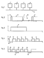
- la fig. 2 représente un exemple de forme d'onde caractérisant un caractère formant un message transmis par un réseau selon la présente invention;
- la fig. 3 représente une forme d'onde caractérisant un signal d'interruption;
- la fig. 4 représente les formes d'ondes d'un message à transmettre selon la présente invention;
- la fig. 5 représente les formes d'ondes d'un autre message selon la présente invention;
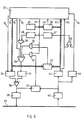
- la fig. 6 représente schématiquement les principaux éléments fonctionnels d'un émetteur-récepteur constituant le réseau selon la présente invention, et
- la fig. 7 représente schématiquement les principaux éléments d'un émetteur-récepteur selon la présente invention.
- fig. 1 schematically represents a network of transceivers according to the present invention;
- fig. 2 shows an example of a waveform characterizing a character forming a message transmitted by a network according to the present invention;
- fig. 3 represents a waveform characterizing an interrupt signal;
- fig. 4 shows the waveforms of a message to be transmitted according to the present invention;
- fig. 5 shows the waveforms of another message according to the present invention;
- fig. 6 schematically represents the main functional elements of a transceiver constituting the network according to the present invention, and
- fig. 7 schematically represents the main elements of a transceiver according to the present invention.
Le procédé de la présente invention permet de faire communiquer, comme le représente schématiquement la fig. 1, plusieurs émetteurs-récepteurs sur un même réseau selon un mode asynchrone. Les émetteurs 1 à 4 sont connectés en parallèle à une même ligne 5. Pour la clarté des dessins, la ligne et les connexions ne comportent qu'un seul conducteur, mais il est clair que deux conducteurs .sont nécessaires. En outre, on pourra, sans sortir du cadre de la présente invention, réaliser des réseaux à transmission sans fil, les émetteurs 1 à 4 étant reliés en parallèle par l'intermédiaire d'ondes hertziennes, ou liaisons optiques telles qu'infrarouges ou fibres optiques.The method of the present invention allows communication, as shown schematically in FIG. 1, several transceivers on the same network in an asynchronous mode. The transmitters 1 to 4 are connected in parallel to the same line 5. For clarity of the drawings, the line and the connections comprise only one conductor, but it is clear that two conductors are necessary. In addition, without departing from the scope of the present invention, wireless transmission networks can be produced, the transmitters 1 to 4 being connected in parallel by radio waves, or optical links such as infrared or fibers. optical.
Dans une transmission de type série asynchrone, l'information transmise ne véhicule pas l'horloge; c'est pourquoi les caractères sont encadrés par un signal binaire de début de caractère et un signal binaire de fin de caractère. Le destinataire utilise le signal binaire de début de caractère pour recaler sa propre horloge et son propre dispositif d'échantillonnage sur une transition. L'échantillonnage est effectué à une fréquence supérieure, de sorte que le calage est suffisant pour toute la durée de transmission d'un caractère. Le calage ainsi réalisé est une fonction essentiellement différente de la synchronisation obtenue par les signaux binaires de début d'émission des transmissions synchrones.In an asynchronous serial type transmission, the information transmitted does not carry the clock; this is why the characters are surrounded by a binary signal at the start of a character and a binary signal at the end of a character. The recipient uses the binary start of character signal to reset his own clock and his own sampling device on a transition. Sampling is performed at a higher frequency, so that the timing is sufficient for the entire duration of transmission of a character. The timing thus achieved is a function essentially different from the synchronization obtained by the binary signals at the start of transmission of the synchronous transmissions.
On a représenté sur la fig. 2 une forme possible de caractère, comprenant un signal binaire de départ 6, suivi de huit signaux binaires dont le codage permet de désigner le caractère à transmettre, le dernier signal binaire étant suivi d'un signal binaire de fin de caractère 7. Le caractère 8 ainsi formé est séparé du caractère 9 suivant par un intervalle 10 de longueur essentiellement variable. La longueur de cet intervalle 10 dépend de la rapidité de traitement des circuits émetteurs entre deux caractères consécutifs. La longueur des caractères 8 ou 9 dépend du nombre de signaux binaires formant ces caractères; généralement, on pourra utiliser cinq à huit signaux binaires, plus éventuellement un signal de parité.There is shown in FIG. 2 a possible form character, comprising a starting binary signal 6, followed by eight binary signals whose coding makes it possible to designate the character to be transmitted, the last binary signal being followed by a binary signal at the end of
La fig. 3 représente, en relation avec la fig. 2, un caractère d'interruption 11 dont la particularité est d'être continu et d'une durée supérieure à celle d'un caractère défini en fig. 2, formant le message.Fig. 3 shows, in relation to FIG. 2, an interrupt
On a représenté sur la fig. 4 la constitution d'un message complet selon le procédé de la présente invention: ce message comprend un signal de début de message 12, formé de préférence par un caractère d'interruption tel que le caractère 11, un second caractère 13 désignant par exemple l'adresse du destinataire du message, un troisième caractère 14 désignant par exemple l'adresse de l'expéditeur, une série de caractères 15 à 16 contenant les caractères du message lui-même à transmettre, et un signal de fin de message 17, de préférence constitué par un caractère d'interruption tel que le caractère 11. Tous ces signaux et caractères formant le message sont constitués de la façon décrite en relation avec la fig. 2 et sont séparés par des intervalles tels que l'intervalle 10 pendant lesquels aucun signal n'est émis sur le réseau.There is shown in FIG. 4 the constitution of a complete message according to the method of the present invention: this message comprises a
Avant de débuter la transmission d'un message tel que le représente la fig. 4, l'expéditeur doit tout d'abord respecter un délai d'attente, représenté par la flèche 18, après le dernier signal 19 détecté sur le réseau. Le délai d'attente 18 doit avoir une durée supérieure à un temps d'attente minimal prédéterminé. Ce temps d'attente minimal est au moins égal au temps de transmission d'un caractère sur le réseau, augmenté du temps de traitement interne habituel d'un circuit émetteur entre la fin de transmission d'un caractère et le début de l'émission du suivant, et augmenté du temps de propagation des signaux entre les points extrêmes du réseau.Before starting the transmission of a message as shown in fig. 4, the sender must first of all respect a waiting time, represented by the
En cours d'émission du message, et à chaque émission de caractère composant ce message, l'expéditeur compare les signaux correspondant au caractère en train d'être émis et les signaux détectés simultanément en écoute. Selon le résultat de cette comparaison, si les signaux sont identiques, l'expéditeur poursuit l'émission du message. Par contre, si les signaux sont différents, l'expéditeur interrompt l'émission du message, émetsur le réseau un caractère d'interruption, reste à l'écoute pendant un délai d'attente, et recommence l'émission à l'issue de ce temps d'écoute. Le délai d'attente doit être différent pour chaque émetteur-récepteur pour que, si plusieurs expéditeurs sont en attente d'émission alors qu'un troisième est en oeuvre, il ne se produise pas de collision systématique à la reprise des émissions. De préférence, ce délai d'attente, toujours supérieur au temps d'attente minimal prédéterminé, a une durée aléatoire pour ne pas introduire de hiérarchie entre les divers émetteurs-récepteurs.During the transmission of the message, and each transmission of character composing this message, the sender compares the signals corresponding to the character being transmitted and the signals detected simultaneously while listening. According to the result of this comparison, if the signals are identical, the sender continues sending the message. On the other hand, if the signals are different, the sender interrupts the transmission of the message, transmits an interrupt character on the network, stays tuned for a waiting period, and starts the transmission again after this listening time. The waiting time must be different for each transceiver so that, if several senders are waiting for transmission while a third is in operation, there will not be a systematic collision when resuming transmissions. Preferably, this waiting time, always greater than the predetermined minimum waiting time, has a random duration so as not to introduce a hierarchy between the various transceivers.
Cette phase du procédé permet d'éviter, d'une part, les mauvaises transmissions des messages et, d'autre part, les collisions intervenant lorsque plusieurs émetteurs-récepteurs débutent une émission en même temps. Dans le cas d'une collision, les premiers caractères des deux messages émis par deux expéditeurs en collision sont des caractères d'interruption, de sorte que chacun des deux expéditeurs détecte l'identité des caractères reçus sur le réseau et des caractères émis. Chacun des deux expéditeurs poursuit donc l'émission en émettant les caractères désignant l'adresse du destinataire. Dans le cas où les adresses des destinataires sont différentes, les signaux présents sur le réseau sont constitués par la combinaison des deux signaux émis, et plusieurs cas sont alors possibles.This phase of the process makes it possible to avoid, on the one hand, bad transmission of messages and, on the other hand, collisions occurring when several transceivers start a transmission at the same time. In the event of a collision, the first characters of the two messages sent by two collision senders are interrupt characters, so that each of the two senders detects the identity of the characters received on the network and of the characters sent. Each of the two senders therefore continues the transmission by issuing the characters designating the address of the recipient. In the case where the addresses of the recipients are different, the signals present on the network are formed by the combination of the two transmitted signals, and several cases are then possible.
Le mélange des informations peut donner une erreur de lecture et/ou de parité de sorte que les deux expéditeurs arrêtent l'émission, émettent un signal d'interruption et attendent un délai aléatoire avant de reprendre cette émission.The mixing of the information can give a reading and / or parity error so that the two senders stop the transmission, emit an interrupt signal and wait for a random delay before resuming this transmission.
Si le mélange des informations et le synchronisme apparent sont tels qu'il apparaisse sur le réseau un caractère représentant une adresse différente de l'adresse d'un au moins des expéditeurs, cet expéditeur détecte l'erreur et émet un signal d'interruption, de sorte que tous les expéditeurs arrêtent leur émission et attendent un délai aléatoire avant la reprise.If the mixture of information and the apparent synchronism are such that there appears on the network a character representing an address different from the address of at least one of the senders, this sender detects the error and sends an interrupt signal, so that all senders stop sending and wait for a random delay before resuming.
Dans le cas où le mélange des informations est tel que la collision n'est pas détectée à ce niveau, les expéditeurs vont transmettre leurs propres adresses qui sont obligatoirement différentes. Dans ce cas, l'un au moins des expéditeurs détectera une différence et produira l'interruption.In the event that the mixture of information is such that the collision is not detected at this level, the senders will transmit their own addresses which are necessarily different. In this case, at least one of the senders will detect a difference and produce the interruption.
Au cours de la phase de comparaison des signaux correspondant au caractère émis et des signaux détectés simultanément en écoute par l'expéditeur, la comparaison est effectuée en fin d'émission du caractère. On peut ainsi utiliser pour cette comparaison les circuits logiques habituels pour comparer des caractères, ce qui conduit à des réalisations peu onéreuses. On pourra cependant effectuer ces comparaisons en fin d'émission de chaque signal binaire contenu dans le caractère.During the phase of comparison of the signals corresponding to the transmitted character and of the signals detected simultaneously by listening by the sender, the comparison is carried out at the end of transmission of the character. One can thus use for this comparison the usual logic circuits to compare characters, which leads to inexpensive realizations. However, these comparisons can be made at the end of transmission of each binary signal contained in the character.
Pendant la phase d'écoute initiale, l'expéditeur doit vérifier qu'aucun message n'est en cours de transmission. Cette vérification peut se faire de deux façons différentes: une première façon consiste à vérifier qu'aucun caractère complet n'a été reçu pendant cette phase d'écoute initiale; dans ce cas, les risques de collision sont relativement élevés, car il est fort probable que deux expéditeurs puissent débuter une émission pendant la durée d'émission d'un caractère. On pourra pour cela préférer une seconde méthode qui consiste à vérifier, d'une part, qu'aucun caractère n'a été reçu pendant la phase d'écoute initiale et que le réseau est à l'état de repos au moment où l'expéditeur envisage de commencer l'émission. Le temps pendant lequel peut se produire une collision est ainsi considérablement réduit.During the initial listening phase, the sender must verify that no message is being transmitted. This verification can be done in two different ways: a first way consists in verifying that no complete character was received during this initial listening phase; in this case, the risk of collision is relatively high, since it is very likely that two senders can start a transmission during the transmission period of a character. We can therefore prefer a second method which consists in verifying, on the one hand, that no character was received during the initial listening phase and that the network is in the idle state when the sender plans to start transmitting. The time during which a collision can occur is thus considerably reduced.
Le procédé de la présente invention prévoit également une phase permettant de produire immédiatement un signal d'accusé de réception envoyé par le destinataire à l'expéditeur, de façon à occuper le réseau pendant un temps minimal. Ce message d'accusé de réception peut comprendre un caractère désignant l'adresse de l'expéditeur, un caractère désignant l'adresse du destinataire, éventuellement des caractères d'information, et un caractère final d'interruption. Le destinataire émet le premier caractère d'accusé de réception avant la fin du temps d'attente minimal prédéterminé qui suit le caractère d'interruption de l'expéditeur signifiant la fin du message. Ainsi, le destinataire est le seul à pouvoir émettre un message avant la fin de ce temps d'attente minimal prédéterminé, de sorte qu'il lui est inutile d'envoyer un caractère d'interruption en début de message d'accusé de réception, les autres expéditeurs ne pouvant émettre avant la fin de ce temps d'attente minimal prédéterminé. On a représenté en fig. 5 la succession des caractères apparaissant sur le réseau lors d'un tel message d'accusé de réception: le dernier caractère 20 du message de l'expéditeur est suivi du caractère 21 d'interruption, caractère 21 qui est suivi, pendant le délai d'attente minimal représenté par la flèche 22, par un premier caractère 23 émis par le destinataire et désignant l'adresse de l'expéditeur, un second caractère 24 désignant l'adresse du destinataire et le caractère d'interruption 25 marquant la fin du message d'accusé de réception. Toute autre émission ne pourra commencer qu'après la fin d'un nouveau délai d'attente 26.The method of the present invention also provides a phase for immediately producing an acknowledgment signal sent by the recipient to the sender, so as to occupy the network for a minimum time. This acknowledgment message can include a character designating the address of the sender, a character designating the address of the recipient, possibly characters of information, and a final character of interruption. The recipient sends the first acknowledgment character before the end of the predetermined minimum waiting time following the interrupt character of the sender signifying the end of the message. Thus, the recipient is the only one able to send a message before the end of this predetermined minimum waiting time, so that there is no need for him to send an interrupt character at the start of an acknowledgment message, the other senders cannot send before the end of this predetermined minimum waiting time. There is shown in fig. 5 the succession of characters appearing on the network during such an acknowledgment message: the
Dans le but de limiter la consommation d'énergie des émetteurs-récepteurs, on pourra chercher à diminuer le temps pendant lequel les différents constituants (sous-ensembles) sont en fonctionnement. Pour cela on définit plusieurs états pour chaque émetteur-récepteur:
- - pendant un état de repos, on ne requiert que le fonctionnement du dispositif de reconnaissance des signaux d'interruption marquant le début et la fin des messages, ce qui peut être réalisé de façon simple à l'aide d'un circuit de temporisation unique;
- - pendant un état d'éveil, l'émetteur-récepteur a reconnu un signal de début de message et attend de reconnaître sa propre adresse pour savoir s'il est destinataire du message. Cet état peut ne durer que le temps de lecture du signal de début de message et du premier caractère contenant l'adresse du destinataire; si l'émetteur-récepteur ne reconnaît pas son adresse, il retourne à l'état de repos;
- - si l'émetteur-récepteur reconnaît son adresse, il entre dans un état d'écoute dans lequel l'unité de traitement prend en compte le message reçu jusqu'à réception d'un signal de fin de message;
- - on distingue en outre un état d'émission dans lequel l'émetteur-récepteur émet des messages sur le réseau ou un accusé de réception tout en restant à l'écoute des signaux présents sur ce réseau.
- - during an idle state, only the operation of the device for recognizing the interrupt signals marking the start and the end of the messages is required, which can be achieved in a simple manner using a single timing circuit ;
- - during an awakening state, the transceiver has recognized a message start signal and is waiting to recognize its own address to know if it is the recipient of the message. This state may only last for the reading time of the message start signal and of the first character containing the address of the recipient; if the transceiver does not recognize its address, it returns to the idle state;
- - if the transceiver recognizes its address, it enters a listening state in which the processing unit takes into account the message received until receipt of an end of message signal;
- - There is also a transmission state in which the transceiver transmits messages on the network or an acknowledgment while remaining attentive to the signals present on this network.
La fig. 6 représente les principaux éléments fonctionnels d'un émetteur-récepteur selon la présente invention. Cet émetteur-récepteur comprend une unité de génération et de traitement des messages 30 comportant plusieurs lignes de sortie 31 véhiculant le caractère à transmettre vers un circuit de sérialisation 36, une ligne de sortie 32 contrôlant la transmission des caractères entre l'unité de génération 30 et le circuit de sérialisation 36, une ligne de sortie 33 connectée à une borne d'entrée d'une porte ET 51 et d'une porte ET 52 pour valider l'émission d'un signal d'interruption 11 en cas de détection de collision lors de la phase de transmission, une ligne de sortie 34 pour commander la transmission du signal de fin de message 17, une ligne de sortie 35 pour commander la transmission du signal de début de message 12 par une porte ET 58. Un circuit 37 de génération des signaux de début de message, de fin de message et d'interruption en cas de collision est commandé par une porte OU 53 dont les bornes d'entrée sont connectées à la ligne 34 et aux bornes de sortie des portes ET 51, 52 et 58. Une porte OU 38 est interposée entre la sortie du circuit de sérialisation 36, la sortie du circuit 37 et l'entrée d'un amplificateur de ligne 39 dont la sortie est connectée au réseau 40.Fig. 6 shows the main functional elements of a transceiver according to the present invention. This transceiver includes a message generation and
L'unité de génération et de traitement de message 30 comporte également plusieurs lignes d'entrée 57 véhiculant le caractère reçu, une ligne d'entrée 55 contrôlant la transmission des caractères entre un circuit de désérialisation 44 et l'unité de traitement 30, une ligne d'entrée 56 raccordée à un circuit 43 de détection du signal d'interruption, une ligne d'entrée 54 raccordée à la sortie d'un circuit comparateur 50 destiné à comparer le caractère reçu sur les lignes 57 à l'adresse de l'équipement émetteur-récepteur définie par un circuit 49.The message generation and
Le circuit désérialisateur 44 et le circuit de détection du signal d'interruption 43 sont connectés à la sortie d'un circuit d'adaptation de ligne 42, lui-même directement connecté au réseau 40.The
La porte OU 46, dont les bornes d'entrées sont connectées aux lignes 55 et 56, détecte la réception d'un caractère ou d'un signal d'interruption et commande un circuit de temporisation 47 chargé d'interdire rémission d'un nouveau message avant un temps minimal prédéterminé. La sortie de ce circuit de temporisation 47 commande un circuit de génération de temporisation aléatoire 48 qui autorisera la transmission de la commande 35 d'émission du signal de début de message au circuit 37 à travers la porte ET 58 et la porte OU 53.The
Sur la figure, on a également représenté les circuits de détection de collision 41 ou 45. Le circuit 41 est utilisé si la comparaison entre signal émis et signal reçu s'effectue après transmission de chaque élément binaire composant les caractères et pendant les intervalles entre chaque caractère. Le circuit 45 est utilisé lorsque la comparaison s'effectue après la transmission de chaque caractère. Les portes ET 51 et 52, validées par la ligne de sortie 33 de l'unité de génération, permettent la transmission du signal de détection de collision vers le circuit générateur du signal d'interruption 37 à travers la porte OU 53.In the figure, the
Dans le mode de réalisation qui précède, les circuits constituant l'émetteur-récepteur peuvent être réalisés par des moyens électroniques bien connus des spécialistes. Pour cette raison, il est inutile de décrire en détail la réalisation de ces circuits. En outre, la réalisation de ces fonctions peut être obtenue de façon particulièrement simple en utilisant la technique des microprocesseurs, comme le décrit le mode de réalisation suivant représenté schématiquement sur la fig. 7. Dans ce mode de réalisation, l'unité logique de commande 70 réalise les fonctions de reconnaissance d'adresse, de comparaison, de détection de collision, de temporisation, de mémorisation des informations et de blocage des émissions comme précédemment décrites. Pour cela, cette unité logique est connectée, d'une part, à l'adaptateur de ligne 42 par la ligne 71, permettant de détecter l'absence d'émission et éventuellement les collisions sur le réseau 40, d'autre part, à un circuit de sérialisation-désérialisation 72 connecté lui-même au réseau à travers l'amplificateur de ligne 39 et l'adaptateur de ligne 42, enfin au circuit 49 définissant l'adresse de l'émetteur-récepteur. Les circuits d'interface série-parallèle tels que le circuit 72 sont couramment utilisés dans les techniques de communication logique, et certains de ces circuits comportent une commande spéciale, non représentée sur la figure, permettant de générer directement en sortie un signal d'interruption 11. Dans le cas où ces circuits ne possèdent pas une telle commande, on pourra de façon simple, comme le représente la fig. 7, générer un tel signal d'interruption au moyen d'un circuit 37 commandé par l'unité logique 70 et produisant sur une porte OU 38 un signal logique continu envoyé sur le réseau 40 par l'amplificateur de ligne 39 pendant un temps prédéterminé supérieur à la durée d'un caractère. La porte 38 est alors interposée entre le circuit 72 et l'amplificateur 39.In the above embodiment, the circuits constituting the transceiver can be produced by electronic means well known to specialists. For this reason, it is unnecessary to describe in detail the construction of these circuits. In addition, the realization of these functions can be obtained in a particularly simple way using the microprocessor technique, as described in the following embodiment shown diagrammatically in FIG. 7. In this embodiment, the
Dans les deux modes de réalisation, l'unité logique de commande, 30 ou 70, permet d'empêcher l'inhibition d'émission pour envoyer un message d'accusé de réception sans attendre le temps d'attente minimal.In both embodiments, the logic control unit, 30 or 70, makes it possible to prevent transmission inhibition in order to send an acknowledgment message without waiting for the minimum waiting time.
Claims (15)
Priority Applications (1)
| Application Number | Priority Date | Filing Date | Title |
|---|---|---|---|
| AT82901720T ATE10055T1 (en) | 1981-06-05 | 1982-06-03 | METHOD AND ARRANGEMENT FOR SERIAL ASYNCHRONOUS COMMUNICATION OF THE MULTIPOINT TYPE BETWEEN SEVERAL LOGICAL TRANSMITTERS-RECEIVERS. |
Applications Claiming Priority (2)
| Application Number | Priority Date | Filing Date | Title |
|---|---|---|---|
| FR8111687A FR2507415A1 (en) | 1981-06-05 | 1981-06-05 | METHOD AND DEVICE FOR ASYNCHRONOUS SERIAL COMMUNICATION OF MULTIPOINTS TYPE OF MULTIPLE LOGIC RECEIVER-RECEIVERS |
| FR8111687 | 1981-06-05 |
Publications (2)
| Publication Number | Publication Date |
|---|---|
| EP0080481A1 EP0080481A1 (en) | 1983-06-08 |
| EP0080481B1 true EP0080481B1 (en) | 1984-10-24 |
Family
ID=9259499
Family Applications (1)
| Application Number | Title | Priority Date | Filing Date |
|---|---|---|---|
| EP82901720A Expired EP0080481B1 (en) | 1981-06-05 | 1982-06-03 | Method and device for the asynchronous series communication of the multipoint type between a plurality of logic transceivers |
Country Status (5)
| Country | Link |
|---|---|
| US (1) | US4584575A (en) |
| EP (1) | EP0080481B1 (en) |
| DE (1) | DE3261051D1 (en) |
| FR (1) | FR2507415A1 (en) |
| WO (1) | WO1982004366A1 (en) |
Families Citing this family (13)
| Publication number | Priority date | Publication date | Assignee | Title |
|---|---|---|---|---|
| US4667192A (en) * | 1983-05-24 | 1987-05-19 | The Johns Hopkins University | Method and apparatus for bus arbitration using a pseudo-random sequence |
| US4539677A (en) * | 1983-07-28 | 1985-09-03 | International Business Machines Corp. | Multiple access data communication system |
| JPS6043942A (en) * | 1983-07-28 | 1985-03-08 | インタ−ナショナル ビジネス マシ−ンズ コ−ポレ−ション | Multiplex access data communication system |
| US4723239A (en) * | 1984-05-12 | 1988-02-02 | Honeywell Gmbh | Serial bus system and method for selection of bus subscribers |
| US4719458A (en) * | 1986-02-24 | 1988-01-12 | Chrysler Motors Corporation | Method of data arbitration and collision detection in a data bus |
| US4739324A (en) * | 1986-05-22 | 1988-04-19 | Chrysler Motors Corporation | Method for serial peripheral interface (SPI) in a serial data bus |
| US4750168A (en) * | 1986-07-07 | 1988-06-07 | Northern Telecom Limited | Channel allocation on a time division multiplex bus |
| FR2631183B1 (en) * | 1988-05-06 | 1991-02-22 | Compex | METHOD AND DEVICE FOR ASYNCHRONOUS PACKET DATA TRANSMISSION |
| CA2005106A1 (en) * | 1989-01-30 | 1990-07-30 | John R. Aggers | Detector for colliding signals in asynchronous communication |
| DE4122084A1 (en) * | 1991-07-04 | 1993-01-07 | Bosch Gmbh Robert | METHOD FOR TRANSFERRING INFORMATION IN A BUS SYSTEM HAVING SEVERAL PARTICIPANTS |
| NL9300441A (en) * | 1993-03-11 | 1994-10-03 | Ericsson Radio Systems Bv | Method of securing data integrity in asynchronous transmission over a common connection, and a communication system for applying the method. |
| US5355375A (en) * | 1993-03-18 | 1994-10-11 | Network Systems Corporation | Hub controller for providing deterministic access to CSMA local area network |
| IT1395644B1 (en) * | 2009-05-27 | 2012-10-16 | Bitmanufaktur Gmbh | WIRELESS HARDWARE DEVICE FOR DETECTION OF RELATIONSHIPS, AND MONITORING SYSTEM FOR DISTANCE RELATIONS BETWEEN WIRELESS HARDWARE DEVICES |
Family Cites Families (7)
| Publication number | Priority date | Publication date | Assignee | Title |
|---|---|---|---|---|
| US4063220A (en) * | 1975-03-31 | 1977-12-13 | Xerox Corporation | Multipoint data communication system with collision detection |
| CH632365A5 (en) * | 1978-01-30 | 1982-09-30 | Patelhold Patentverwertung | DATA EXCHANGE PROCESS BETWEEN MULTIPLE PARTNERS. |
| US4210780A (en) * | 1978-03-27 | 1980-07-01 | The Mitre Corporation | Multiple access digital communications system |
| US4292623A (en) * | 1979-06-29 | 1981-09-29 | International Business Machines Corporation | Port logic for a communication bus system |
| US4271505A (en) * | 1979-07-02 | 1981-06-02 | The Foxboro Company | Process communication link |
| GB2058418A (en) * | 1979-07-06 | 1981-04-08 | Ward Goldstone Ltd | A multiplex information handling system |
| US4332027A (en) * | 1981-10-01 | 1982-05-25 | Burroughs Corporation | Local area contention network data communication system |
-
1981
- 1981-06-05 FR FR8111687A patent/FR2507415A1/en active Granted
-
1982
- 1982-06-03 EP EP82901720A patent/EP0080481B1/en not_active Expired
- 1982-06-03 US US06/464,499 patent/US4584575A/en not_active Expired - Fee Related
- 1982-06-03 DE DE8282901720T patent/DE3261051D1/en not_active Expired
- 1982-06-03 WO PCT/FR1982/000092 patent/WO1982004366A1/en active IP Right Grant
Also Published As
| Publication number | Publication date |
|---|---|
| FR2507415A1 (en) | 1982-12-10 |
| FR2507415B1 (en) | 1985-03-22 |
| EP0080481A1 (en) | 1983-06-08 |
| US4584575A (en) | 1986-04-22 |
| DE3261051D1 (en) | 1984-11-29 |
| WO1982004366A1 (en) | 1982-12-09 |
Similar Documents
| Publication | Publication Date | Title |
|---|---|---|
| EP0080481B1 (en) | Method and device for the asynchronous series communication of the multipoint type between a plurality of logic transceivers | |
| EP0517609B1 (en) | Method and arbitration bus for transmission of serial data | |
| FR2579342A1 (en) | LOCAL DATA TRANSMISSION NETWORK AND METHOD OF AUTOMATICALLY ALLOCATING ADDRESSES TO DATA PROCESSING DEVICES THEREFOR | |
| FR2579341A1 (en) | LOCAL DATA TRANSMISSION NETWORK HAVING A SIGNAL DETECTION SYSTEM, PREVENTING COLLISIONS AND DATA TRANSFER METHOD IN SUCH A NETWORK | |
| EP0333558B1 (en) | Testing device for a local area network with carrier sense access and collision detection (csma/cd) | |
| FR2578070A1 (en) | METHOD FOR OPERATING A DATA PROCESSING FACILITY FOR MOTOR VEHICLES | |
| FR2619477A1 (en) | BASE STATION FOR WIRELESS TELEPHONE SYSTEM | |
| EP0520877B1 (en) | Method and device for managing information transmission over mains applied to a domestic network | |
| EP0407279A1 (en) | Communication network between user equipment | |
| FR2539935A1 (en) | IMPROVED COLLISION DETECTION METHOD | |
| EP0108692A1 (en) | Method and installation for digital data transmission | |
| FR2631183A1 (en) | METHOD AND DEVICE FOR ASYNCHRONOUS PACKET DATA TRANSMISSION | |
| EP0849914B1 (en) | Collision detection by transmitting data over a radio network | |
| EP0384795B1 (en) | Method and device for transmitting information between stations of a communication network, especially for a motor vehicle | |
| EP0635184B1 (en) | Data transmission device and method for random access network having advanced collision resolution | |
| EP0380378B1 (en) | Method and device for the hierarchical access to an information transmission network | |
| EP0843931A1 (en) | Communication method using an optical bus simultaneously supporting different data rates | |
| EP0178205B1 (en) | Digital multiple-access network | |
| WO1981001932A1 (en) | Communication control device in a duplex transmission network | |
| EP0637417B1 (en) | Radio network-type data transmission method and facility | |
| EP0341175A1 (en) | Multiple access by distributed traffic control in a local area communication network | |
| EP0924893B1 (en) | Secure communication procedure | |
| EP0931406B1 (en) | Method for synchronous transmission of digital data, in particular using an asynchronous communication processor | |
| FR2631184A1 (en) | Method and device for synchronous transmission of data in packets | |
| FR2505110A1 (en) | Redundant digital information transmission system - uses six frequency pulses in coded sequence to be received within time windows in order to reduce possibility of noise interference |
Legal Events
| Date | Code | Title | Description |
|---|---|---|---|
| PUAI | Public reference made under article 153(3) epc to a published international application that has entered the european phase |
Free format text: ORIGINAL CODE: 0009012 |
|
| AK | Designated contracting states |
Designated state(s): AT BE CH DE FR GB LI LU NL SE |
|
| 17P | Request for examination filed |
Effective date: 19830604 |
|
| GRAA | (expected) grant |
Free format text: ORIGINAL CODE: 0009210 |
|
| AK | Designated contracting states |
Designated state(s): AT BE CH DE FR GB LI LU NL SE |
|
| REF | Corresponds to: |
Ref document number: 10055 Country of ref document: AT Date of ref document: 19841115 Kind code of ref document: T |
|
| REF | Corresponds to: |
Ref document number: 3261051 Country of ref document: DE Date of ref document: 19841129 |
|
| PLBE | No opposition filed within time limit |
Free format text: ORIGINAL CODE: 0009261 |
|
| STAA | Information on the status of an ep patent application or granted ep patent |
Free format text: STATUS: NO OPPOSITION FILED WITHIN TIME LIMIT |
|
| 26N | No opposition filed | ||
| REG | Reference to a national code |
Ref country code: FR Ref legal event code: TP |
|
| PGFP | Annual fee paid to national office [announced via postgrant information from national office to epo] |
Ref country code: LU Payment date: 19920527 Year of fee payment: 11 Ref country code: GB Payment date: 19920527 Year of fee payment: 11 |
|
| PGFP | Annual fee paid to national office [announced via postgrant information from national office to epo] |
Ref country code: SE Payment date: 19920615 Year of fee payment: 11 |
|
| PGFP | Annual fee paid to national office [announced via postgrant information from national office to epo] |
Ref country code: BE Payment date: 19920623 Year of fee payment: 11 |
|
| PGFP | Annual fee paid to national office [announced via postgrant information from national office to epo] |
Ref country code: NL Payment date: 19920630 Year of fee payment: 11 Ref country code: AT Payment date: 19920630 Year of fee payment: 11 |
|
| PGFP | Annual fee paid to national office [announced via postgrant information from national office to epo] |
Ref country code: DE Payment date: 19920728 Year of fee payment: 11 |
|
| PGFP | Annual fee paid to national office [announced via postgrant information from national office to epo] |
Ref country code: CH Payment date: 19920928 Year of fee payment: 11 |
|
| EPTA | Lu: last paid annual fee | ||
| PG25 | Lapsed in a contracting state [announced via postgrant information from national office to epo] |
Ref country code: LU Free format text: LAPSE BECAUSE OF NON-PAYMENT OF DUE FEES Effective date: 19930603 Ref country code: GB Effective date: 19930603 Ref country code: AT Effective date: 19930603 |
|
| PG25 | Lapsed in a contracting state [announced via postgrant information from national office to epo] |
Ref country code: SE Effective date: 19930604 |
|
| PG25 | Lapsed in a contracting state [announced via postgrant information from national office to epo] |
Ref country code: LI Effective date: 19930630 Ref country code: CH Effective date: 19930630 Ref country code: BE Effective date: 19930630 |
|
| BERE | Be: lapsed |
Owner name: RYCKEBOER CHRISTIAN Effective date: 19930630 |
|
| PG25 | Lapsed in a contracting state [announced via postgrant information from national office to epo] |
Ref country code: NL Effective date: 19940101 |
|
| REG | Reference to a national code |
Ref country code: FR Ref legal event code: TP |
|
| GBPC | Gb: european patent ceased through non-payment of renewal fee |
Effective date: 19930603 |
|
| NLV4 | Nl: lapsed or anulled due to non-payment of the annual fee | ||
| REG | Reference to a national code |
Ref country code: CH Ref legal event code: PL |
|
| PG25 | Lapsed in a contracting state [announced via postgrant information from national office to epo] |
Ref country code: DE Effective date: 19940301 |
|
| EUG | Se: european patent has lapsed |
Ref document number: 82901720.1 Effective date: 19940110 |
|
| PGFP | Annual fee paid to national office [announced via postgrant information from national office to epo] |
Ref country code: FR Payment date: 19980610 Year of fee payment: 17 |
|
| PG25 | Lapsed in a contracting state [announced via postgrant information from national office to epo] |
Ref country code: FR Free format text: THE PATENT HAS BEEN ANNULLED BY A DECISION OF A NATIONAL AUTHORITY Effective date: 19990630 |
|
| REG | Reference to a national code |
Ref country code: FR Ref legal event code: ST |