EP0080446A2 - Machine à percussion et procédé de contrôle de ladite machine - Google Patents
Machine à percussion et procédé de contrôle de ladite machine Download PDFInfo
- Publication number
- EP0080446A2 EP0080446A2 EP82850229A EP82850229A EP0080446A2 EP 0080446 A2 EP0080446 A2 EP 0080446A2 EP 82850229 A EP82850229 A EP 82850229A EP 82850229 A EP82850229 A EP 82850229A EP 0080446 A2 EP0080446 A2 EP 0080446A2
- Authority
- EP
- European Patent Office
- Prior art keywords
- piston
- impact
- hammer piston
- wave energy
- shock waves
- Prior art date
- Legal status (The legal status is an assumption and is not a legal conclusion. Google has not performed a legal analysis and makes no representation as to the accuracy of the status listed.)
- Withdrawn
Links
- 238000000034 method Methods 0.000 title claims description 7
- 230000035939 shock Effects 0.000 claims abstract description 29
- 230000003116 impacting effect Effects 0.000 claims description 2
- 238000013016 damping Methods 0.000 abstract description 25
- 239000011435 rock Substances 0.000 abstract description 18
- 230000006835 compression Effects 0.000 description 5
- 238000007906 compression Methods 0.000 description 5
- 230000007423 decrease Effects 0.000 description 3
- 238000005553 drilling Methods 0.000 description 3
- 230000035515 penetration Effects 0.000 description 3
- 239000012530 fluid Substances 0.000 description 2
- 238000013022 venting Methods 0.000 description 2
- 230000001133 acceleration Effects 0.000 description 1
- 230000006378 damage Effects 0.000 description 1
- 230000000737 periodic effect Effects 0.000 description 1
Images


Classifications
-
- B—PERFORMING OPERATIONS; TRANSPORTING
- B25—HAND TOOLS; PORTABLE POWER-DRIVEN TOOLS; MANIPULATORS
- B25D—PERCUSSIVE TOOLS
- B25D17/00—Details of, or accessories for, portable power-driven percussive tools
- B25D17/24—Damping the reaction force
- B25D17/245—Damping the reaction force using a fluid
-
- E—FIXED CONSTRUCTIONS
- E21—EARTH DRILLING; MINING
- E21B—EARTH DRILLING, e.g. DEEP DRILLING; OBTAINING OIL, GAS, WATER, SOLUBLE OR MELTABLE MATERIALS OR A SLURRY OF MINERALS FROM WELLS
- E21B1/00—Percussion drilling
- E21B1/38—Hammer piston type, i.e. in which the tool bit or anvil is hit by an impulse member
-
- B—PERFORMING OPERATIONS; TRANSPORTING
- B25—HAND TOOLS; PORTABLE POWER-DRIVEN TOOLS; MANIPULATORS
- B25D—PERCUSSIVE TOOLS
- B25D9/00—Portable percussive tools with fluid-pressure drive, i.e. driven directly by fluids, e.g. having several percussive tool bits operated simultaneously
- B25D9/06—Means for driving the impulse member
- B25D9/12—Means for driving the impulse member comprising a built-in liquid motor, i.e. the tool being driven by hydraulic pressure
-
- B—PERFORMING OPERATIONS; TRANSPORTING
- B25—HAND TOOLS; PORTABLE POWER-DRIVEN TOOLS; MANIPULATORS
- B25D—PERCUSSIVE TOOLS
- B25D9/00—Portable percussive tools with fluid-pressure drive, i.e. driven directly by fluids, e.g. having several percussive tool bits operated simultaneously
- B25D9/14—Control devices for the reciprocating piston
- B25D9/145—Control devices for the reciprocating piston for hydraulically actuated hammers having an accumulator
-
- B—PERFORMING OPERATIONS; TRANSPORTING
- B25—HAND TOOLS; PORTABLE POWER-DRIVEN TOOLS; MANIPULATORS
- B25D—PERCUSSIVE TOOLS
- B25D9/00—Portable percussive tools with fluid-pressure drive, i.e. driven directly by fluids, e.g. having several percussive tool bits operated simultaneously
- B25D9/14—Control devices for the reciprocating piston
- B25D9/26—Control devices for adjusting the stroke of the piston or the force or frequency of impact thereof
Definitions
- This invention relates to a method of controlling an impact motor that comprises a reciprocating hammer piston that, when impacting upon an anvil, converts its kinetic energy to shock wave energy that propagates through an elongate tool, for example a tool in the form of a drill stem or chisel.
- the invention relates also to an impact motor of the kind described above which has an adjusting device for adjusting the impact velocity of the hammer piston.
- the hammer piston impacts at a constant impact energy per blow independently of the gradually varying condition of the drill bit and of changing rock properties.
- the impact motor can then for example be the impact motor of a rock drill or a jack hammer. This object is achieved by the features given in the characterizing parts of the claims.
- the kinetic energy of the hammer piston propagates in the form of a compression wave through the tool which can be a rock drill stem.
- the major portion of the part of the shock wave energy that is not utilized for the rock destruction is reflected as shock wave energy either ii. the form of compression waves or tensile waves. This energy may also be reflected partly as compression waves and partly as tensile waves.
- the reflected shock waves are sensed and the impact velocity is adjusted in response thereto so that the reflected shock wave energy will be small.
- the movement coupled to the reflected shock waves is sensed and the movement is minimized.
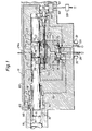
- the impact device shown in Fig 1 is a hydraulic rock drill, a hydraulic jack hammer or the like. It comprises a housing 11 forming a cylinder 12 in which a hammer piston 13 is reciprocable to impact upon an anvil element 14, for example a chisel, a rock drill stem or an adapter for a rock drill stem.
- a shoulder 15 on the anvil element takes support on a sleeve 16 on a damping piston 17 for damping the reflected compressive shock waves.
- the damping piston 17 is forced forwardly into its foremost position as shown by the hydraulic pressure in a cylinder chamber 18 that is constantly pressurized through a passage 19. The pressure acts on an annular piston surface 9 of the damping piston.
- the hammer piston 13 has two lands 20, 21 so that a front cylinder chamber 22, a rear cylinder chamber 23 and an intermediate cylinder chamber 24 are formed between the piston 13 and the cylinder 12.
- the piston 13 is driven forwardly by the pressure acting on its surface 25 and driven rearwardly by the pressure acting on its surface 26.
- a valve 27 is connected to an inlet 28 coupled to a source of high pressure hydraulic fluid and to an outlet 29 coupled to tank. Accumulators 30, 31 are coupled to the inlet 28 and the outlet 29.
- the intermediate cylinder chamber 24 is constantly connected to the outlet 29 by means of a passage 29a.
- the valve 27 is coupled to the rear cylinder chamber 23 by means of a supply passage 32 and to the front cylinder chamber 22 by means of a supply passage 33.
- the valve 27 has a valving spool 34 which in its illustrated position connects the rear cylinder chamber 23 to pressure and the front cylinder chamber 22 to tank.
- the spool 34 has cylindrical end portions 35, 36, the end faces of which have piston surfaces that are subject to the pressure in control passages 37, 42 that each are branched into four branches so that they each have four ports 38, 39, 40, 41 and 43, 44, 45, 46 respectively into the cylinder 12.
- a cylindrical bore 47 intersects all eight branches and a cylindrical pin 48 is slidable with a tight fit in the bore 47.
- This pin 48 has two recesses 49, 50. Integral with the pin 48 there is a control piston 55 that divides a cylinder into two cylinder chambers 56, 57 and a dash pot piston 58.
- Compressed air is supplied through a pressure regulator 59 to the two cylinder chambers 56, 57 via two passages 60, 61.
- the passage 61 contains a restriction 62.
- a passage 63 leads from the cylinder chamber 57 to a cylinder chamber 64 formed between the housing 11 and a land 65 on the damping piston 17.
- the front end face 66 of the land abuts against a shoulder 67 in the housing 11 to define the impact position of the anvil element 14.
- One or more passages 68 lead axially through the land 65 and they are closed when the damping piston 17 is forced forwardly into its normal positon as shown in Fig 1 but they are vented through a passage 69 to the atmosphere when the damping piston 17 is off the shoulder 67.
- the operation of the impact device of Fig 1 will now be described.
- the hammer piston 13 is shown in Fig 1 moving forwardly in its work stroke (to the left in Fig 1), and the valve spool 34 is then in its illustrated position.
- the control passage 42 will convey pressure to the control piston 36 so that the valve spool 34 is moved to the right in Fig 1.
- the valve spool 34 should prefereably finish its movement at the very moment the hammer piston 13 impacts upon the anvil 14.
- the pressure existing from the moment of impact in the front cylinder chamber 22 moves the hammer piston 13 rearwardly until the branch 40 of the control passage 37 is opended to the front pressure chamber 22.
- control passage 37 conveys pressure to the control piston 35 which moves the valve spool 34 back to its illustrated position so that the rear cylinder chamber 23 is again pressurized.
- the pressure in the rear cylinder chamber 23 retards the hammer piston 13 and accelerates it forwardly again so that the hammer piston 13 performs another work stroke.
- the valve spool 34 has annular surfaces 52, 53 and internal passages 51, 54 which hold the valve spool in position during the periods when the control pistons 35, 36 do not positively hold the piston.
- the annular surfaces52, 53 are smaller than the end faces of the pistons 35, 36.
- the port 40 of the control passage 37 and the port 45 of the control passage 42 are the ports that make the valve spool shift position.
- the other ports are inactivated.
- one pair of the three pairs of ports 38, 43; 39, 44 and 41, 46 respectively is selected to cooperate to control the valve.
- the first one of the ports 38-41 that is opened to the front cylinder chamber 22 during the return stroke of the hammer piston initiates the valve spool 34 to shift position.
- the operator pre-selects the stroke length of the hammer piston.
- the axial distances between the ports 43-46 are smaller than the corresponding distances between the ports 38-41.
- the axial positions of the ports 43-46 in the cylinder are such that for each stroke length the selected one of the ports 43-46 is uncovered a distance before the impact postion of the hammer piston, and the distance is such that the valve spool has just moved to its position for pressurizing the front pressure chamber when the hammer piston 13 impacts the anvil 14.
- the distances between the ports 43-46 are such that the selected port is uncovered the same period of time before impact occurs independently of which one of the four ports is selected.
- the damping piston 17 When there are no reflected compressive shock waves, the damping piston 17 will not rebounce and the passage 63 will be constantly blocked. Thus, there will be a pressure balance on the piston 55.
- the differential area of the piston 55 will move the piston to the left in Fig 1 and the stroke length. of the hammer piston will accordingly decrease until the damping piston 17 starts to rebounce.
- the periodic rebounce will cause air to leak through the passage 63 so that the pressure in the chamber 57 decreases and the piston will stop moving to the left in Fig l.
- the piston should be so balanced that it takes up a position in which the damping piston 17 rebounces only a little, which means that a slight amount of energy reflects as compression waves.
- the balance of the piston is defined by its differential area, the restriction 62, the supplied air pressure, and of course the damping piston 17.
- the dash-pot piston 58 slows down the movement of the damping piston 17, and makes the control more stable.
- the stroke length is automatically reduced so that the drill bit will not wear down unnecessarily fast. Then, the stroke length increases as the drill bit becomes worn.
- the stroke length is also automatically adjusted to varying rock properties and to the length of the drill stem when the drill stem is made up of extention rods.
- FIG 2 an alternative system for controlling the pin 48 is shown.
- a plunger piston 71 is fixed with the pin 48 and a passage 72 with a check valve 73 leads directly between the cylinder chamber 18 of the damping piston 17 and the cylinder chamber 74 of the plunger piston 71.
- the check valve 73 is by-passed by a passage 75 with a restriction 76.
- An annular land 77 between the pin 48 and the plunger piston 71 divides a wider cylinder into two cylinder chambers 78, 79.
- the cylinder chamber 78 is continuously drained through a passage 80 and the cylinder chamber 79 is continuously pressurized through a passage 81.
- the annular area in the cylinder chamber 79 should equal the plunger area.
- a spring 82 is arranged to bias the pin 48 to the left in Fig 2.
- the rebounces of the damping piston 17 result in pressure peaks in the chamber 18.
- the check valve 73 which is closed at the normal pressure level, opens for each peak and supplies a small amount of fluid to the plunger cylinder 74, and the plunger piston 71 will move the pin 48 to the right in the figure against the action of the spring so that the stroke length of the hammer piston 13 increases as described with reference to Fig 1.
- the spring 82 will force the plunger 71 and the pin 48 to the left in Fig 2 until the rebounces again tend to increase.
- the pin 48 will be controlled in response to the compressive shock waves as in the embodiment of Fig 1.
- the damping piston 17 is biassed forwardly into a defined normal position into which it returns or nearly returns before each impact provided that the feed force applied to the housing 11 is smaller than the force applied to the piston surface 9 of the damping piston.
- an hydraulic impact motor which has a valve 27 and a valve control system that accepts variation within certain limits of the position of the impact surface of the anvil at the instant of impact. Therefore, the damping piston 17 can be floating as shown in Fig 3.
- the pin 48 controls the valve control passage 37 only, it does not control the valve control passage 42.
- the pin 48 is controlled by compressed air of a controlled pressure in the same way as shown in Fig 1 but the venting of the passage 63 is different.
- the chamber 18 is supplied with compressed air of a controlled pressure from a supply passage 85 through a check valve 86 so that the air in the chamber 18 forms an air spring.
- a counter piston 87 has an annular piston surface 88 in a cylinder chamber 87 which is, in use, constantly pressurized by being connected to the supply passage 85.
- the piston surface 88 of the counter piston 87 must be substantially smaller than the piston surface 9 of the damping piston 17.
- the movement related to the reflected compressive shock waves only is sensed. Neither the primary compressive shock waves nor the reflected tensile shock waves will induce rebounces of the damping piston 17, which makes the system very simple.
- the movements of the drill stem can be sensed, for example by means of light emitter, a bundle of optic fibres and a photocell.
- the electric signal from the photocell can then be analyzed and processed to give a control signal for controlling a control pin 48 of the kind shown in the Figures or any other kind of means for adjusting the impact velocity of the hammer piston.
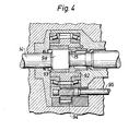
- the impact device shown in Figs 1, 2, or 3 is a rock drill, its front end can be as shown in Fig 4.
- the shoulder 15 of the anvil element 14 is the rear end surface 15 of a non-circular widened portion 98 of a drill stem adapter 14.
- the portion 98 engages with a chuck bushing 92 with an insert bushing 93 so that it rotates conjointly with the chuck bushing.
- the chuck bushing 92 is rotated by means of a non-illustrated rotation motor through a drive shaft 95 and a gearing 94.
- ports 38-41 with four respective passages that intersect the bore 47 and only four ports 43-46 with four respective passages that intersect the bore 47 are shown, it is advantageous and desirable that the discrete ports and their passages axially overlap one another in order to make the control substantially stepless.
- the ports and the respective passages can for example be arranged in two or three axial rows so that they axially overlap one another but still remain discrete.
Applications Claiming Priority (2)
| Application Number | Priority Date | Filing Date | Title |
|---|---|---|---|
| SE8106907 | 1981-11-20 | ||
| SE8106907A SE8106907L (sv) | 1981-11-20 | 1981-11-20 | Sett att styra ett slagverk och slagverk |
Publications (2)
| Publication Number | Publication Date |
|---|---|
| EP0080446A2 true EP0080446A2 (fr) | 1983-06-01 |
| EP0080446A3 EP0080446A3 (fr) | 1985-01-23 |
Family
ID=20345077
Family Applications (1)
| Application Number | Title | Priority Date | Filing Date |
|---|---|---|---|
| EP82850229A Withdrawn EP0080446A3 (fr) | 1981-11-20 | 1982-11-12 | Machine à percussion et procédé de contrôle de ladite machine |
Country Status (3)
| Country | Link |
|---|---|
| EP (1) | EP0080446A3 (fr) |
| JP (1) | JPS5890476A (fr) |
| SE (1) | SE8106907L (fr) |
Cited By (23)
| Publication number | Priority date | Publication date | Assignee | Title |
|---|---|---|---|---|
| EP0112810A2 (fr) * | 1982-12-27 | 1984-07-04 | Atlas Copco Aktiebolag | Appareil pour forer dans la roche, et procédé pour obtenir un forage par percussion de rendement optimal |
| EP0214064A1 (fr) * | 1985-07-16 | 1987-03-11 | Etablissements Montabert | Procédé de commande du mouvement du piston de frappe d'un appareil à percussions mû par un fluide incompressible sous pression, et appareil pour la mise en oeuvre de ce procédé |
| FR2598111A1 (fr) * | 1986-05-02 | 1987-11-06 | Tampella Oy Ab | Agencement pour le palier axial d'une machine de forage |
| FR2602448A1 (fr) * | 1986-08-07 | 1988-02-12 | Montabert Ets | Procede de regulation des parametres de percussion du piston de frappe d'un appareil mu par un fluide incompressible sous pression, et appareil pour la mise en oeuvre de ce procede |
| EP0389454A1 (fr) * | 1989-02-21 | 1990-09-26 | Atlas Copco Construction and Mining Technique AB | Dispositif dans des machines à percussion |
| FR2647870A1 (fr) * | 1989-06-06 | 1990-12-07 | Eimco Secoma | Appareil de percussion hydraulique avec dispositif d'amortissement des ondes de choc en retour |
| EP0471649A1 (fr) * | 1990-08-16 | 1992-02-19 | SIG Schweizerische Industrie-Gesellschaft | Marteau actionné par un fluide de pression |
| EP0475171A2 (fr) * | 1990-09-08 | 1992-03-18 | Krupp Maschinentechnik Gesellschaft Mit Beschränkter Haftung | Mécanisme à coup actionné hydrauliquement |
| EP0522344A2 (fr) * | 1991-07-09 | 1993-01-13 | Bretec Oy | Marteau à coup hydraulique |
| EP0715932A1 (fr) * | 1994-12-08 | 1996-06-12 | Etablissements Montabert | Procédé et appareil pour la régulation de la course de frappe d'un appareil à percussion mû par un fluide incompressible sous pression |
| DE19545708A1 (de) * | 1995-12-07 | 1997-06-12 | Krupp Bautechnik Gmbh | Verfahren zur Beeinflussung des Betriebsverhaltens eines fluidbetriebenen Schlagwerks und zur Durchführung des Verfahrens geeignetes Schlagwerk |
| WO2001083170A1 (fr) * | 2000-04-28 | 2001-11-08 | Oy Robit Rocktools Ltd | Procede et dispositif pour regler l'energie de percussion dans une perceuse a percussion |
| WO2003078107A1 (fr) * | 2002-03-19 | 2003-09-25 | Montabert S.A. | Marteau perforateur hydraulique roto-percutant |
| WO2004042193A1 (fr) * | 2002-11-05 | 2004-05-21 | Sandvik Tamrock Oy | Dispositif pour commander le forage de roche |
| WO2006003259A1 (fr) * | 2004-07-02 | 2006-01-12 | Sandvik Mining And Construction Oy | Procede de commande d'un dispositif de percussion, produit logiciel et dispositif de percussion |
| EP2059369A1 (fr) * | 2006-09-13 | 2009-05-20 | Atlas Copco Rock Drills AB | Dispositif à percussion, perforatrice comprenant un tel dispositif à percussion et procédé permettant de commander un tel dispositif à percussion |
| WO2010037905A1 (fr) * | 2008-09-30 | 2010-04-08 | Sandvik Mining And Construction Oy | Procédé et agencement dans une installation de forage de roche |
| CN101370621B (zh) * | 2006-02-20 | 2010-11-10 | 阿特拉斯科普科凿岩机股份公司 | 冲击装置和包括这种冲击装置的凿岩机 |
| EP2614217A1 (fr) | 2010-09-10 | 2013-07-17 | Rockdrill Services Australia Pty Ltd | Fleuret de mine amélioré |
| WO2015122824A1 (fr) * | 2014-02-14 | 2015-08-20 | Atlas Copco Rock Drills Ab | Dispositif d'amortissement pour dispositif de percussion, dispositif de percussion, et perforatrice de roches |
| EP2566665A4 (fr) * | 2010-05-03 | 2016-04-13 | Atlas Copco Rock Drills Ab | Perceuse |
| US9511489B2 (en) | 2011-04-27 | 2016-12-06 | Atlas Copco Rock Drills Ab | Impact mechanism, rock drill and drill rig comprising such impact mechanism |
| FR3077752A1 (fr) * | 2018-02-14 | 2019-08-16 | Montabert | Perforateur hydraulique roto-percutant pourvu d’une chambre de commande reliee en permanence a un accumulateur basse pression |
Families Citing this family (1)
| Publication number | Priority date | Publication date | Assignee | Title |
|---|---|---|---|---|
| JP6495672B2 (ja) * | 2015-01-30 | 2019-04-03 | 古河ロックドリル株式会社 | 液圧式打撃装置、並びにバルブタイミングの切換方法およびバルブポートの設定方法 |
Citations (3)
| Publication number | Priority date | Publication date | Assignee | Title |
|---|---|---|---|---|
| FR2304449A1 (fr) * | 1975-03-18 | 1976-10-15 | Atlas Copco Ab | Amortisseur de rebond pour outil a percussion |
| DE2654200A1 (de) * | 1975-12-18 | 1977-06-23 | Roger Montabert | Schlagvorrichtung |
| EP0035005A1 (fr) * | 1980-02-20 | 1981-09-02 | Atlas Copco Aktiebolag | Dispositif à percussion hydraulique |
-
1981
- 1981-11-20 SE SE8106907A patent/SE8106907L/ not_active Application Discontinuation
-
1982
- 1982-11-12 EP EP82850229A patent/EP0080446A3/fr not_active Withdrawn
- 1982-11-19 JP JP57202196A patent/JPS5890476A/ja active Pending
Patent Citations (3)
| Publication number | Priority date | Publication date | Assignee | Title |
|---|---|---|---|---|
| FR2304449A1 (fr) * | 1975-03-18 | 1976-10-15 | Atlas Copco Ab | Amortisseur de rebond pour outil a percussion |
| DE2654200A1 (de) * | 1975-12-18 | 1977-06-23 | Roger Montabert | Schlagvorrichtung |
| EP0035005A1 (fr) * | 1980-02-20 | 1981-09-02 | Atlas Copco Aktiebolag | Dispositif à percussion hydraulique |
Cited By (50)
| Publication number | Priority date | Publication date | Assignee | Title |
|---|---|---|---|---|
| EP0112810A2 (fr) * | 1982-12-27 | 1984-07-04 | Atlas Copco Aktiebolag | Appareil pour forer dans la roche, et procédé pour obtenir un forage par percussion de rendement optimal |
| EP0112810A3 (fr) * | 1982-12-27 | 1985-08-28 | Atlas Copco Aktiebolag | Appareil pour forer dans la roche, et procédé pour obtenir un forage par percussion de rendement optimal |
| EP0214064A1 (fr) * | 1985-07-16 | 1987-03-11 | Etablissements Montabert | Procédé de commande du mouvement du piston de frappe d'un appareil à percussions mû par un fluide incompressible sous pression, et appareil pour la mise en oeuvre de ce procédé |
| FR2595972A2 (fr) * | 1985-07-16 | 1987-09-25 | Montabert Ets | Appareil a percussions |
| FR2598111A1 (fr) * | 1986-05-02 | 1987-11-06 | Tampella Oy Ab | Agencement pour le palier axial d'une machine de forage |
| FR2602448A1 (fr) * | 1986-08-07 | 1988-02-12 | Montabert Ets | Procede de regulation des parametres de percussion du piston de frappe d'un appareil mu par un fluide incompressible sous pression, et appareil pour la mise en oeuvre de ce procede |
| EP0256955A1 (fr) * | 1986-08-07 | 1988-02-24 | Etablissements Montabert | Procédé de régulation des paramètres de percussion du piston de frappe d'un appareil mû par un fluide incompressible sous pression, et appareil pour la mise en oeuvre de ce procédé |
| EP0389454A1 (fr) * | 1989-02-21 | 1990-09-26 | Atlas Copco Construction and Mining Technique AB | Dispositif dans des machines à percussion |
| FR2647870A1 (fr) * | 1989-06-06 | 1990-12-07 | Eimco Secoma | Appareil de percussion hydraulique avec dispositif d'amortissement des ondes de choc en retour |
| US5056606A (en) * | 1989-06-06 | 1991-10-15 | Eimco-Secoma (Societe Anonyme) | Damped hammer drill |
| EP0471649A1 (fr) * | 1990-08-16 | 1992-02-19 | SIG Schweizerische Industrie-Gesellschaft | Marteau actionné par un fluide de pression |
| EP0475171A3 (en) * | 1990-09-08 | 1992-05-20 | Krupp Maschinentechnik Gesellschaft Mit Beschraenkter Haftung | Hydraulically operated percussion mechanism |
| EP0475171A2 (fr) * | 1990-09-08 | 1992-03-18 | Krupp Maschinentechnik Gesellschaft Mit Beschränkter Haftung | Mécanisme à coup actionné hydrauliquement |
| EP0522344A2 (fr) * | 1991-07-09 | 1993-01-13 | Bretec Oy | Marteau à coup hydraulique |
| EP0522344A3 (en) * | 1991-07-09 | 1993-07-28 | Rammer Bretec Oy | Hydraulic impact hammer |
| US5669281A (en) * | 1994-12-08 | 1997-09-23 | Etablissements Montabert | Method and machine for altering the striking stroke of a percussive machine moved by a pressurized incompressible fluid |
| FR2727891A1 (fr) * | 1994-12-08 | 1996-06-14 | Montabert Ets | Procede et appareil pour la regulation de la course de frappe d'un appareil a percussion mu par un fluide incompressible sous pression |
| EP0715932A1 (fr) * | 1994-12-08 | 1996-06-12 | Etablissements Montabert | Procédé et appareil pour la régulation de la course de frappe d'un appareil à percussion mû par un fluide incompressible sous pression |
| DE19545708A1 (de) * | 1995-12-07 | 1997-06-12 | Krupp Bautechnik Gmbh | Verfahren zur Beeinflussung des Betriebsverhaltens eines fluidbetriebenen Schlagwerks und zur Durchführung des Verfahrens geeignetes Schlagwerk |
| WO2001083170A1 (fr) * | 2000-04-28 | 2001-11-08 | Oy Robit Rocktools Ltd | Procede et dispositif pour regler l'energie de percussion dans une perceuse a percussion |
| WO2003078107A1 (fr) * | 2002-03-19 | 2003-09-25 | Montabert S.A. | Marteau perforateur hydraulique roto-percutant |
| FR2837523A1 (fr) * | 2002-03-19 | 2003-09-26 | Montabert Sa | Marteau perforateur hydraulique roto-percutant |
| US7234548B2 (en) | 2002-03-19 | 2007-06-26 | Montabert S.A. | Hydraulic rotary-percussive hammer drill |
| US7654337B2 (en) | 2002-11-05 | 2010-02-02 | Sandvik Mining And Construction Oy | Arrangement for controlling rock drilling |
| WO2004042193A1 (fr) * | 2002-11-05 | 2004-05-21 | Sandvik Tamrock Oy | Dispositif pour commander le forage de roche |
| WO2006003259A1 (fr) * | 2004-07-02 | 2006-01-12 | Sandvik Mining And Construction Oy | Procede de commande d'un dispositif de percussion, produit logiciel et dispositif de percussion |
| AU2005259128B2 (en) * | 2004-07-02 | 2010-02-18 | Sandvik Mining And Construction Oy | Method for controlling percussion device, software product, and percussion device |
| US7717190B2 (en) | 2004-07-02 | 2010-05-18 | Sandvik Mining And Construction Oy | Method for controlling percussion device, software production, and percussion device |
| CN101370621B (zh) * | 2006-02-20 | 2010-11-10 | 阿特拉斯科普科凿岩机股份公司 | 冲击装置和包括这种冲击装置的凿岩机 |
| EP2059369A4 (fr) * | 2006-09-13 | 2013-04-24 | Atlas Copco Rock Drills Ab | Dispositif à percussion, perforatrice comprenant un tel dispositif à percussion et procédé permettant de commander un tel dispositif à percussion |
| EP2059369A1 (fr) * | 2006-09-13 | 2009-05-20 | Atlas Copco Rock Drills AB | Dispositif à percussion, perforatrice comprenant un tel dispositif à percussion et procédé permettant de commander un tel dispositif à percussion |
| CN102164714B (zh) * | 2008-09-30 | 2014-05-07 | 山特维克矿山工程机械有限公司 | 钻岩设备中的装备及方法 |
| WO2010037905A1 (fr) * | 2008-09-30 | 2010-04-08 | Sandvik Mining And Construction Oy | Procédé et agencement dans une installation de forage de roche |
| CN102164714A (zh) * | 2008-09-30 | 2011-08-24 | 山特维克矿山工程机械有限公司 | 钻岩设备中的装备及方法 |
| AU2009299713B2 (en) * | 2008-09-30 | 2013-08-29 | Sandvik Mining And Construction Oy | Method and arrangement in rock drilling rig |
| EP2566665A4 (fr) * | 2010-05-03 | 2016-04-13 | Atlas Copco Rock Drills Ab | Perceuse |
| EP2614217A4 (fr) * | 2010-09-10 | 2015-10-07 | Rockdrill Services Australia Pty Ltd | Fleuret de mine amélioré |
| EP2614217A1 (fr) | 2010-09-10 | 2013-07-17 | Rockdrill Services Australia Pty Ltd | Fleuret de mine amélioré |
| US9511489B2 (en) | 2011-04-27 | 2016-12-06 | Atlas Copco Rock Drills Ab | Impact mechanism, rock drill and drill rig comprising such impact mechanism |
| EP3105415A4 (fr) * | 2014-02-14 | 2017-10-25 | Atlas Copco Rock Drills AB | Dispositif d'amortissement pour dispositif de percussion, dispositif de percussion, et perforatrice de roches |
| KR20160119074A (ko) * | 2014-02-14 | 2016-10-12 | 아트라스 콥코 록 드릴스 에이비 | 충격 장치를 위한 감쇠 장치와, 충격 장치 및 암반 굴착 기계 |
| CN105980658A (zh) * | 2014-02-14 | 2016-09-28 | 阿特拉斯·科普柯凿岩设备有限公司 | 用于撞击装置的缓冲装置、撞击装置和凿岩机 |
| WO2015122824A1 (fr) * | 2014-02-14 | 2015-08-20 | Atlas Copco Rock Drills Ab | Dispositif d'amortissement pour dispositif de percussion, dispositif de percussion, et perforatrice de roches |
| CN105980658B (zh) * | 2014-02-14 | 2019-06-14 | 安百拓凿岩有限公司 | 用于撞击装置的缓冲装置、撞击装置和凿岩机 |
| US10456898B2 (en) | 2014-02-14 | 2019-10-29 | Epiroc Rock Drills Aktiebolag | Damping device for a percussion device, percussion device and rock drilling machine |
| FR3077752A1 (fr) * | 2018-02-14 | 2019-08-16 | Montabert | Perforateur hydraulique roto-percutant pourvu d’une chambre de commande reliee en permanence a un accumulateur basse pression |
| WO2019158834A1 (fr) * | 2018-02-14 | 2019-08-22 | Montabert | Perforateur hydraulique roto-percutant pourvu d'une chambre de commande reliée en permanence à un accumulateur basse pression |
| CN111712353A (zh) * | 2018-02-14 | 2020-09-25 | 蒙塔博特公司 | 设置有与低压蓄能器永久连接的控制室的旋转冲击式液压穿孔器 |
| CN111712353B (zh) * | 2018-02-14 | 2023-03-21 | 蒙塔博特公司 | 设置有与低压蓄能器永久连接的控制室的旋转冲击式液压穿孔器 |
| US11724379B2 (en) | 2018-02-14 | 2023-08-15 | Montabert | Rotary-percussive hydraulic perforator provided with a control chamber permanently connected to a low-pressure accumulator |
Also Published As
| Publication number | Publication date |
|---|---|
| EP0080446A3 (fr) | 1985-01-23 |
| JPS5890476A (ja) | 1983-05-30 |
| SE8106907L (sv) | 1983-05-21 |
Similar Documents
| Publication | Publication Date | Title |
|---|---|---|
| EP0080446A2 (fr) | Machine à percussion et procédé de contrôle de ladite machine | |
| EP0058650B1 (fr) | Appareil de percussion actionné hydrauliquement | |
| US4800797A (en) | Hydraulic percussion device and method of controlling same | |
| EP0112810A2 (fr) | Appareil pour forer dans la roche, et procédé pour obtenir un forage par percussion de rendement optimal | |
| EP0035005B1 (fr) | Dispositif à percussion hydraulique | |
| US5392865A (en) | Hydraulic percussion apparatus | |
| US4006783A (en) | Hydraulic operated rock drilling apparatus | |
| US3965799A (en) | Hydraulically operated percussion device | |
| US4899836A (en) | Hydraulic percussion instrument and method of operating same | |
| US5419403A (en) | Pneumatic hammer | |
| GB1515442A (en) | Hydraulic percussion tool with impact blow and frequency control | |
| ES461657A1 (es) | Perfeccionamientos en aparatos hidraulicos de percusiones. | |
| SE529615C2 (sv) | Slagverk och bergborrmaskin samt förfarande för att styra slagkolvens slaglängd | |
| US3741072A (en) | Hydraulic fluid actuated percussion tool | |
| GB1262170A (en) | Hydraulically actuated percussive tools | |
| US5113950A (en) | For percussive tools, a housing, a pneumatic distributor, and a hammer piston means therefor | |
| US4563938A (en) | Pressure fluid operated percussive tool | |
| ATE21713T1 (de) | Hydraulische pfahlrammanlage. | |
| US8453756B2 (en) | Rock drilling equipment and a method in association with same | |
| US5350023A (en) | Pneumatic hammer | |
| EP0070044B1 (fr) | Moteur de percussion hydraulique | |
| EP0265401A2 (fr) | Dispositif d'amortissement pour une machine de forage de roche à percussion | |
| US4450920A (en) | Hydraulic reciprocating machines | |
| FI90277B (fi) | Porauslaite | |
| GB1373848A (en) | Hydraulic breaker operated by oil |
Legal Events
| Date | Code | Title | Description |
|---|---|---|---|
| PUAI | Public reference made under article 153(3) epc to a published international application that has entered the european phase |
Free format text: ORIGINAL CODE: 0009012 |
|
| AK | Designated contracting states |
Designated state(s): AT CH DE FR GB IT LI SE |
|
| PUAL | Search report despatched |
Free format text: ORIGINAL CODE: 0009013 |
|
| AK | Designated contracting states |
Designated state(s): AT CH DE FR GB IT LI SE |
|
| RAP1 | Party data changed (applicant data changed or rights of an application transferred) |
Owner name: ATLAS COPCO AKTIEBOLAG |
|
| STAA | Information on the status of an ep patent application or granted ep patent |
Free format text: STATUS: THE APPLICATION IS DEEMED TO BE WITHDRAWN |
|
| 18D | Application deemed to be withdrawn |
Effective date: 19850924 |
|
| RIN1 | Information on inventor provided before grant (corrected) |
Inventor name: WIJK, AXEL GUNNAR Inventor name: ANDERSSON, KURT HOLGER |