EP0080243B1 - Bras de suspension pour l'accrochage d'une cuve de machine à laver dans sa carrosserie et machine à laver ainsi équipée - Google Patents
Bras de suspension pour l'accrochage d'une cuve de machine à laver dans sa carrosserie et machine à laver ainsi équipée Download PDFInfo
- Publication number
- EP0080243B1 EP0080243B1 EP19820201479 EP82201479A EP0080243B1 EP 0080243 B1 EP0080243 B1 EP 0080243B1 EP 19820201479 EP19820201479 EP 19820201479 EP 82201479 A EP82201479 A EP 82201479A EP 0080243 B1 EP0080243 B1 EP 0080243B1
- Authority
- EP
- European Patent Office
- Prior art keywords
- tube
- arm
- washing machine
- tub
- mounting portion
- Prior art date
- Legal status (The legal status is an assumption and is not a legal conclusion. Google has not performed a legal analysis and makes no representation as to the accuracy of the status listed.)
- Expired
Links
- 239000000725 suspension Substances 0.000 title claims description 18
- 238000005406 washing Methods 0.000 title claims description 12
- 239000004033 plastic Substances 0.000 claims description 5
- 229920003023 plastic Polymers 0.000 claims description 5
- 239000002184 metal Substances 0.000 claims description 2
- 238000010412 laundry washing Methods 0.000 claims 1
- XLYOFNOQVPJJNP-UHFFFAOYSA-N water Substances O XLYOFNOQVPJJNP-UHFFFAOYSA-N 0.000 description 5
- 238000009987 spinning Methods 0.000 description 4
- 239000006096 absorbing agent Substances 0.000 description 3
- 238000002788 crimping Methods 0.000 description 3
- 230000010355 oscillation Effects 0.000 description 3
- 230000035939 shock Effects 0.000 description 3
- 238000010276 construction Methods 0.000 description 2
- 229930182556 Polyacetal Natural products 0.000 description 1
- VHCQVGQULWFQTM-VOTSOKGWSA-N Rubone Chemical compound COC1=CC(OC)=CC(O)=C1C(=O)\C=C\C1=CC(OC)=C(OC)C=C1OC VHCQVGQULWFQTM-VOTSOKGWSA-N 0.000 description 1
- VHCQVGQULWFQTM-UHFFFAOYSA-N Rubone Natural products COC1=CC(OC)=CC(O)=C1C(=O)C=CC1=CC(OC)=C(OC)C=C1OC VHCQVGQULWFQTM-UHFFFAOYSA-N 0.000 description 1
- 230000001133 acceleration Effects 0.000 description 1
- 230000000712 assembly Effects 0.000 description 1
- 238000000429 assembly Methods 0.000 description 1
- 210000003323 beak Anatomy 0.000 description 1
- 230000006835 compression Effects 0.000 description 1
- 238000007906 compression Methods 0.000 description 1
- 238000013016 damping Methods 0.000 description 1
- 230000017525 heat dissipation Effects 0.000 description 1
- 230000014759 maintenance of location Effects 0.000 description 1
- 229920006122 polyamide resin Polymers 0.000 description 1
- 229920006324 polyoxymethylene Polymers 0.000 description 1
- 239000007787 solid Substances 0.000 description 1
- 230000001131 transforming effect Effects 0.000 description 1
Images
Classifications
-
- F—MECHANICAL ENGINEERING; LIGHTING; HEATING; WEAPONS; BLASTING
- F16—ENGINEERING ELEMENTS AND UNITS; GENERAL MEASURES FOR PRODUCING AND MAINTAINING EFFECTIVE FUNCTIONING OF MACHINES OR INSTALLATIONS; THERMAL INSULATION IN GENERAL
- F16F—SPRINGS; SHOCK-ABSORBERS; MEANS FOR DAMPING VIBRATION
- F16F7/00—Vibration-dampers; Shock-absorbers
- F16F7/08—Vibration-dampers; Shock-absorbers with friction surfaces rectilinearly movable along each other
- F16F7/09—Vibration-dampers; Shock-absorbers with friction surfaces rectilinearly movable along each other in dampers of the cylinder-and-piston type
-
- D—TEXTILES; PAPER
- D06—TREATMENT OF TEXTILES OR THE LIKE; LAUNDERING; FLEXIBLE MATERIALS NOT OTHERWISE PROVIDED FOR
- D06F—LAUNDERING, DRYING, IRONING, PRESSING OR FOLDING TEXTILE ARTICLES
- D06F37/00—Details specific to washing machines covered by groups D06F21/00 - D06F25/00
- D06F37/20—Mountings, e.g. resilient mountings, for the rotary receptacle, motor, tub or casing; Preventing or damping vibrations
Definitions
- the present invention relates to an extensible and damped suspension arm for hooking a washing machine tub and spinning the laundry in its body, arm comprising a tension spring at the ends anchored in two hooking ends. It is known to hang the tub of a washing machine in the chassis or the body of the machine, by means of elastic extensible devices with mechanically damped travel. German patent application DE-Ai 460885 discloses such a device.
- the spring is crimped there by its extreme turns on the two end pieces and a shock absorber is arranged inside the spring.
- the damper consists of a rod sliding in a friction ring, the rod sliding, moreover, in a guide tube.
- the spring in a damped suspension arm, is housed in the cavity of a plastic tube integral with the first end piece, said sliding tube with friction in a cylindrical envelope elastically enclosing it, consisting of metal plates mounted at one end on the second endpiece, parallel to the axis of the tube and on which they are held tight by at least one elastic ring.
- a construction is simple and makes it possible in particular to use a spiral spring with curved ends hung in eyelets drilled in the end pieces, which avoids the delicate crimping of the terminal turns.
- the friction surface of the shock absorber is increased by increasing its diameter, the shock absorber surrounding the spring, and its length, all of the plates of the cylindrical envelope enclosing the plastic tube.
- French patent application IR-A-2 384 995 discloses an elastic and damped telescopic device for a washing machine tub, in which the damper surrounds the spring. But it is a device on which the tank is placed, commonly called "foot".
- the spring works there in compression, which does not make it appear the need for attachment or crimping to the end pieces.
- a suspension arm and a "foot do not behave in the same way when working. The large oscillations of the tank which they must brake occur during the acceleration of the spinning drum, while the tank is completely or largely emptied, therefore lightened.
- the surfaces facing the friction elements are small when the foot is in extension. This probably justifies the provision of pads with a high coefficient of friction of FR-A-2 384 995. But these pads have a drawback: in addition to their cost and that of their attachment to the elastic sleeve, they limit the thermal contact, therefore the dissipation heat from the friction zone to the atmosphere, through the outer sleeve.
- the facing surfaces of the friction elements are large when the arm is retracted. This eliminates the need for additional friction pads and ensures heat dissipation by the outer plates of the sleeve.
- the suspension arm is characterized in that at least one plate constituting the envelope is notched on one of its longitudinal edges, so as to present a transverse spout close to its end opposite to the second endpiece, spout capable of cooperating with a lug projecting from the surface of the tube, opposite the first endpiece, in order to create a stop for maximum extension of the arm.
- the tank full of water rests on the stops of the suspension arms, which does not present any disadvantage, the vibrations generated by the drum rotating at low speed (50 revolutions per minute for example) being negligible.
- These stops make it possible to avoid any contact between the tank or the engine of the machine, which is generally fixed at its lower part, with the base of the machine or the members that it supports.
- the vibrations generated by the unbalanced linen are absorbed by the arms whose springs, discharged from the weight of the water, are not more in maximum extension.
- the invention also relates to a washing machine, the tub of which is attached to suspension arms of the type described above.
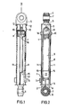
- the suspension arm given as an example is equipped with a spiral spring 1 intended to work in traction, the curved ends of which are hooked in holes or eyelets 2 and 3 made in two end pieces 4 and 5.
- the end pieces 4 and 5 are fitted with elastic sleeves 6 traversed by bearings 7 for fixing the arm by means of an axis on the tank, on the one hand, and on the body or the chassis of the washing machine, on the other go. Any other mode of articulation of the nozzles 4 and 5 on the tank and bodywork can be envisaged.
- the ends 4 and 5 are molded, for example, from a polyacetal or polyamide resin.
- the end piece 4 is molded in one piece with a tube 8 extending practically up to the end piece 5 when the spring is relaxed.
- the endpiece 5 carries two symmetrical transverse studs 10 on which are hung two plates 11, pierced for this purpose, constituting an envelope around the tube 8.
- the plates 11, preferably metallic, are in the form of almost semi-circular cylindrical shells and enclose the tube 8 of which they cover substantially the entire length when the spring is relaxed.
- the plates 11 are identical.
- the end piece 5 comprises, in the longitudinal alignment of the pins 10, two grooves 12 in which the ends of the shells 11 are engaged, for their transverse retention.
- the shells 11 are clamped on the tube 8 by an elastic ring 13 or a stirrup formed by a spring leaf. This tightening establishes the friction which allows the suspension arm to transform the kinetic energy of vibration into heat, when the tank which is attached to it oscillates.
- the shells 11 are flared at 14, so as not to have an abrasive edge in contact with the tube 8.
- the shells 11 are notched on one of their longitudinal edges and over almost their entire length in order to present a transverse beak. Between the shells 11, in the indented area, there can circulate a lug 16 belonging to the tube 8 and whose travel is free up to the spout 15 which thus constitutes a stop for maximum extension of the arm.
- the tube 8 carries two diametrically opposite lugs 16, located at the end opposite to the end piece 4.
- the tube 8 has a notch 17, close to its end attached to the end piece 4. This notch facilitates the attachment of the spring 1 in the orifice 2 of the end piece 4.
- the suspension arm described with the figures works as follows.
- the nozzles 4 and 5, attached respectively to the body and to the tank of the washing machine are joined by the spring 1 only, and are therefore free to oscillate relative to each other, recalled by the force of the spring.
- Solid with these end pieces, the tube 8 and the envelope formed by the shells 11 rub one inside the other, transforming the kinetic energy of oscillation into heat which is dissipated in the ambient atmosphere by the shells 11.
- the pins 16 of the tube rest on the spouts 15 of the envelope and the tank is no longer suspended elastically.
- the spring is moderately stretched and, for example, the pins 16 oscillate around a median position halfway up the envelope.
Landscapes
- Engineering & Computer Science (AREA)
- General Engineering & Computer Science (AREA)
- Textile Engineering (AREA)
- Mechanical Engineering (AREA)
- Springs (AREA)
- Main Body Construction Of Washing Machines And Laundry Dryers (AREA)
- Accessory Of Washing/Drying Machine, Commercial Washing/Drying Machine, Other Washing/Drying Machine (AREA)
Applications Claiming Priority (2)
| Application Number | Priority Date | Filing Date | Title |
|---|---|---|---|
| FR8122042 | 1981-11-25 | ||
| FR8122042A FR2516952A1 (fr) | 1981-11-25 | 1981-11-25 | Bras de suspension pour l'accrochage d'une cuve de machine a laver dans sa carrosserie et machine a laver ainsi equipee |
Publications (2)
| Publication Number | Publication Date |
|---|---|
| EP0080243A1 EP0080243A1 (fr) | 1983-06-01 |
| EP0080243B1 true EP0080243B1 (fr) | 1985-02-20 |
Family
ID=9264344
Family Applications (1)
| Application Number | Title | Priority Date | Filing Date |
|---|---|---|---|
| EP19820201479 Expired EP0080243B1 (fr) | 1981-11-25 | 1982-11-22 | Bras de suspension pour l'accrochage d'une cuve de machine à laver dans sa carrosserie et machine à laver ainsi équipée |
Country Status (4)
| Country | Link |
|---|---|
| EP (1) | EP0080243B1 (enExample) |
| DE (2) | DE8232579U1 (enExample) |
| ES (1) | ES277944Y (enExample) |
| FR (1) | FR2516952A1 (enExample) |
Families Citing this family (4)
| Publication number | Priority date | Publication date | Assignee | Title |
|---|---|---|---|---|
| FR2605336B1 (fr) * | 1986-10-17 | 1989-05-26 | Philips Ind Commerciale | Bras de suspension pour cuve de machine a laver le linge et machine a laver le linge ainsi equipee. |
| DE3725100A1 (de) * | 1987-07-29 | 1989-02-09 | Bauer Fritz & Soehne Ohg | Schwingungsdaempfer, insbesondere fuer waschmaschinen |
| EP0949373A1 (de) * | 1998-03-10 | 1999-10-13 | SUSPA COMPART Aktiengesellschaft | Reibungsdämpfer, insbesondere für Waschmaschinen mit Schleudergang |
| US11964631B2 (en) * | 2018-04-10 | 2024-04-23 | Piolax, Inc. | Damper device |
Family Cites Families (7)
| Publication number | Priority date | Publication date | Assignee | Title |
|---|---|---|---|---|
| BE671161A (enExample) * | 1964-11-13 | 1966-02-14 | ||
| DE1460885A1 (de) * | 1965-03-02 | 1969-06-26 | Constructa Werke Gmbh | Halterung fuer ein schwingbewegliches Trommelaggregat einer Wasch- und Schleudermaschine |
| FR1570563A (enExample) * | 1968-03-25 | 1969-06-13 | ||
| US3744746A (en) * | 1971-09-23 | 1973-07-10 | Whirlpool Co | Suspension rod assembly for automatic washer |
| US3889937A (en) * | 1974-01-16 | 1975-06-17 | Lowell E Statler | Friction-type shock absorber |
| FR2384995A1 (fr) * | 1977-03-23 | 1978-10-20 | Esswein Sa | Dispositif d'amortissement a friction, notamment pour cuve de machine a laver, et machine a laver comportant un tel dispositif |
| FR2459912A2 (fr) * | 1979-06-27 | 1981-01-16 | Esswein Sa | Dispositif d'amortissement a friction, notamment pour cuve de machine a laver, et machine a laver comportant un tel dispositif |
-
1981
- 1981-11-25 FR FR8122042A patent/FR2516952A1/fr active Granted
-
1982
- 1982-11-20 DE DE19828232579 patent/DE8232579U1/de not_active Expired
- 1982-11-22 DE DE8282201479T patent/DE3262454D1/de not_active Expired
- 1982-11-22 EP EP19820201479 patent/EP0080243B1/fr not_active Expired
- 1982-11-23 ES ES1982277944U patent/ES277944Y/es not_active Expired
Also Published As
| Publication number | Publication date |
|---|---|
| FR2516952A1 (fr) | 1983-05-27 |
| FR2516952B1 (enExample) | 1985-03-08 |
| EP0080243A1 (fr) | 1983-06-01 |
| ES277944U (es) | 1984-10-01 |
| ES277944Y (es) | 1985-04-01 |
| DE8232579U1 (de) | 1983-05-19 |
| DE3262454D1 (en) | 1985-03-28 |
Similar Documents
| Publication | Publication Date | Title |
|---|---|---|
| FR3047470B1 (fr) | Atterrisseur pour aeronef comportant un amortisseur principal et un amortisseur secondaire anti shimmy | |
| EP0006036B1 (fr) | Dispositif protecteur, notamment pour tige d'amortisseur télescopique | |
| EP0080243B1 (fr) | Bras de suspension pour l'accrochage d'une cuve de machine à laver dans sa carrosserie et machine à laver ainsi équipée | |
| EP0026018A1 (fr) | Machine à laver et à essorer le linge à entraînement du tambour par courroie immergée | |
| FR2631435A1 (fr) | Dispositif de support de fleche escamotable pour arc | |
| EP0773362B1 (fr) | Dispositif pour la suspension d'une pompe et/ou d'une crépine appartenant à un ensemble de pompage | |
| FR2508822A1 (fr) | Centrifugeuse a broche entrainee par une transmission par courroie | |
| FR2734876A1 (fr) | Piece de liaison a absorption d'energie et siege d'aeronef equipe d'une telle piece | |
| EP0265004B1 (fr) | Bras de suspension pour cuve de machine à laver le linge et machine à laver le linge ainsi équipée | |
| FR2535440A1 (fr) | Dispositif a electrode equipant un bruleur a huile ou a gaz | |
| FR2600837A1 (fr) | Dispositif de protection pour un cable, tel qu'un fil a haute tension | |
| FR2793732A1 (fr) | Dispositif de fixation superieure d'un amortisseur de suspension d'une roue avant d'un vehicule automobile | |
| EP0027753B2 (fr) | Dispositif d'amortissement à double effet, et machine à laver et/ou essorer le linge munie d'un tel dispositif | |
| CA1330853C (fr) | Dispositif de fixation d'un tampon de matiere fibreuse et machine de nettoyage de surface equipee dudit dispositif | |
| EP3008361A1 (fr) | Ensemble pivotant monte au niveau d'une boite de vitesses d'un vehicule automobile pour le passage et la selection des vitesses | |
| EP1293701B1 (fr) | Support antivibratoire et dispositif antivibratoire comportant un tel support | |
| FR2459912A2 (fr) | Dispositif d'amortissement a friction, notamment pour cuve de machine a laver, et machine a laver comportant un tel dispositif | |
| FR2761303A1 (fr) | Dispositif de fixation de l'extremite superieure d'une jambe de suspension sur la caisse d'un vehicule | |
| FR2829560A1 (fr) | Dispositif d'eclairage transportable tel qu'une baladeuse | |
| FR2849139A1 (fr) | Dispositif de fixation superieure d'un amortisseur de suspension d'une roue avant d'un vehicule automobile | |
| FR2488922A1 (fr) | Machine a laver et a essorer le linge a entrainement du tambour par courroie immergee | |
| FR3127364A1 (fr) | Porte-sécateur ergonomique | |
| FR2607209A1 (fr) | Dispositif de suspension permettant d'isoler des equipements sensibles aux chocs ou aux vibrations | |
| CH643332A5 (en) | Damper for a mechanised handling device | |
| FR2486360A3 (fr) | Dispositif pour l'attache rapide d'une ligne a une canne a peche |
Legal Events
| Date | Code | Title | Description |
|---|---|---|---|
| PUAI | Public reference made under article 153(3) epc to a published international application that has entered the european phase |
Free format text: ORIGINAL CODE: 0009012 |
|
| 17P | Request for examination filed |
Effective date: 19821122 |
|
| AK | Designated contracting states |
Designated state(s): DE FR GB IT |
|
| ITF | It: translation for a ep patent filed | ||
| GRAA | (expected) grant |
Free format text: ORIGINAL CODE: 0009210 |
|
| AK | Designated contracting states |
Designated state(s): DE FR GB IT |
|
| REF | Corresponds to: |
Ref document number: 3262454 Country of ref document: DE Date of ref document: 19850328 |
|
| PLBE | No opposition filed within time limit |
Free format text: ORIGINAL CODE: 0009261 |
|
| STAA | Information on the status of an ep patent application or granted ep patent |
Free format text: STATUS: NO OPPOSITION FILED WITHIN TIME LIMIT |
|
| 26N | No opposition filed | ||
| REG | Reference to a national code |
Ref country code: FR Ref legal event code: TP |
|
| REG | Reference to a national code |
Ref country code: GB Ref legal event code: 732 |
|
| REG | Reference to a national code |
Ref country code: FR Ref legal event code: TP |
|
| ITPR | It: changes in ownership of a european patent |
Owner name: CESSIONE;WHIRLPOOL INTERNATIONAL B.V. |
|
| REG | Reference to a national code |
Ref country code: FR Ref legal event code: CD |
|
| ITTA | It: last paid annual fee | ||
| PGFP | Annual fee paid to national office [announced via postgrant information from national office to epo] |
Ref country code: FR Payment date: 19961111 Year of fee payment: 15 |
|
| PGFP | Annual fee paid to national office [announced via postgrant information from national office to epo] |
Ref country code: GB Payment date: 19961113 Year of fee payment: 15 |
|
| PGFP | Annual fee paid to national office [announced via postgrant information from national office to epo] |
Ref country code: DE Payment date: 19970123 Year of fee payment: 15 |
|
| PG25 | Lapsed in a contracting state [announced via postgrant information from national office to epo] |
Ref country code: GB Free format text: LAPSE BECAUSE OF NON-PAYMENT OF DUE FEES Effective date: 19971122 |
|
| PG25 | Lapsed in a contracting state [announced via postgrant information from national office to epo] |
Ref country code: FR Free format text: THE PATENT HAS BEEN ANNULLED BY A DECISION OF A NATIONAL AUTHORITY Effective date: 19971130 |
|
| GBPC | Gb: european patent ceased through non-payment of renewal fee |
Effective date: 19971122 |
|
| PG25 | Lapsed in a contracting state [announced via postgrant information from national office to epo] |
Ref country code: DE Free format text: LAPSE BECAUSE OF NON-PAYMENT OF DUE FEES Effective date: 19980801 |
|
| REG | Reference to a national code |
Ref country code: FR Ref legal event code: ST |