EP0079744A2 - Clutch assembly for removing a severed wafer from an ingot - Google Patents
Clutch assembly for removing a severed wafer from an ingot Download PDFInfo
- Publication number
- EP0079744A2 EP0079744A2 EP82305945A EP82305945A EP0079744A2 EP 0079744 A2 EP0079744 A2 EP 0079744A2 EP 82305945 A EP82305945 A EP 82305945A EP 82305945 A EP82305945 A EP 82305945A EP 0079744 A2 EP0079744 A2 EP 0079744A2
- Authority
- EP
- European Patent Office
- Prior art keywords
- head
- wafer
- carriage
- slide
- blade
- Prior art date
- Legal status (The legal status is an assumption and is not a legal conclusion. Google has not performed a legal analysis and makes no representation as to the accuracy of the status listed.)
- Granted
Links
Images


Classifications
-
- B—PERFORMING OPERATIONS; TRANSPORTING
- B28—WORKING CEMENT, CLAY, OR STONE
- B28D—WORKING STONE OR STONE-LIKE MATERIALS
- B28D5/00—Fine working of gems, jewels, crystals, e.g. of semiconductor material; apparatus or devices therefor
- B28D5/0058—Accessories specially adapted for use with machines for fine working of gems, jewels, crystals, e.g. of semiconductor material
- B28D5/0082—Accessories specially adapted for use with machines for fine working of gems, jewels, crystals, e.g. of semiconductor material for supporting, holding, feeding, conveying or discharging work
- B28D5/0094—Accessories specially adapted for use with machines for fine working of gems, jewels, crystals, e.g. of semiconductor material for supporting, holding, feeding, conveying or discharging work the supporting or holding device being of the vacuum type
-
- B—PERFORMING OPERATIONS; TRANSPORTING
- B23—MACHINE TOOLS; METAL-WORKING NOT OTHERWISE PROVIDED FOR
- B23Q—DETAILS, COMPONENTS, OR ACCESSORIES FOR MACHINE TOOLS, e.g. ARRANGEMENTS FOR COPYING OR CONTROLLING; MACHINE TOOLS IN GENERAL CHARACTERISED BY THE CONSTRUCTION OF PARTICULAR DETAILS OR COMPONENTS; COMBINATIONS OR ASSOCIATIONS OF METAL-WORKING MACHINES, NOT DIRECTED TO A PARTICULAR RESULT
- B23Q7/00—Arrangements for handling work specially combined with or arranged in, or specially adapted for use in connection with, machine tools, e.g. for conveying, loading, positioning, discharging, sorting
- B23Q7/04—Arrangements for handling work specially combined with or arranged in, or specially adapted for use in connection with, machine tools, e.g. for conveying, loading, positioning, discharging, sorting by means of grippers
- B23Q7/047—Arrangements for handling work specially combined with or arranged in, or specially adapted for use in connection with, machine tools, e.g. for conveying, loading, positioning, discharging, sorting by means of grippers the gripper supporting the workpiece during machining
-
- B—PERFORMING OPERATIONS; TRANSPORTING
- B28—WORKING CEMENT, CLAY, OR STONE
- B28D—WORKING STONE OR STONE-LIKE MATERIALS
- B28D5/00—Fine working of gems, jewels, crystals, e.g. of semiconductor material; apparatus or devices therefor
- B28D5/02—Fine working of gems, jewels, crystals, e.g. of semiconductor material; apparatus or devices therefor by rotary tools, e.g. drills
- B28D5/022—Fine working of gems, jewels, crystals, e.g. of semiconductor material; apparatus or devices therefor by rotary tools, e.g. drills by cutting with discs or wheels
- B28D5/028—Fine working of gems, jewels, crystals, e.g. of semiconductor material; apparatus or devices therefor by rotary tools, e.g. drills by cutting with discs or wheels with a ring blade having an inside cutting edge
Definitions
- This invention relates to a wafering system. More particularly, this invention relates to a chuck assembly for removing a severed wafer from an ingot. Still more particularly, this invention relates to a method of severing and removing a wafer from an ingot.
- the crystals are of a type such as silicon, germanium, and the like, which can be used in the semi-conductor industry. In such cases, the wafers which are severed from the crystal must be accurately made and must have smooth surfaces.
- Patent 3,577,861 with a crystal oriented in a vertical position and the annular cutting member positioned in a horizontal plane, it has been known to employ a retrieval system which has one suction member below the crystal and cutting member for initially receiving and holding a severed wafer and a second suction member above the annular member out of the plane of the crystal to receive the severed wafer from the first suction member.
- a retrieval system requires the timing and the accurate positioning of a multiplicity of components in order to effect retrieval of a severed wafer from the crystal as well as a number of operations for transferring the severed wafer from one suction member to another.
- the annular cutting member has been mounted on a hollow shaft so that a severed wafer can be removed through the hollow shaft by a suitable means.
- this creates a cumbersome machine and requires a relatively large space for the machine.
- the invention provides a wafering system which is comprised of a rotary cutting blade having a bore and a cutting edge about the bore for severing a wafer from a delivered ingot, a chuck assembly having a head for engaging a severed wafer from the ingot, and means for moving the head between a rest position on one side of the blade and a wafer holding position on an opposite side of the blade.
- the wafering system also includes a means for feeding an ingot perpendicularly into the bore of the cutting blade for slicing of thin wafers from the ingot during a relative transverse movement between the blade and the ingot.
- the chuck assembly also includes an arm which is secured to and which extends from the head and an arm assembly which has the arm mounted thereon.
- the arm assembly is pivotally mounted on a slide so as to pivot about a first axis.
- the slide is, in turn, movably mounted on a carriage along a second axis which is perpendicular to the first axis.
- the carriage in turn, is movable along a third axis perpendicular to the pivot axis and the axis along which the slide moves.
- the carriage is mounted so as to move in a pertical plane along a carriage guide.
- the slide is then movable via a suitable reciprocating means over a predetermined stroke and the arm assembly is pivotable about a horizontal axis via a suitable means.
- the arm of the arm assembly is formed with a straight section which extends from the arm assembly as well as a bent section on which the head is mounted in offset relation to the straight section.
- the construction is such that the head can be moved into and through the plane of the bore in the cutting blade when a severed wafer is to be retrieved and back through the bore after the wafer has been retrieved.
- a suitable programming means is provided for actuating the various movements of the carriage, slide and arm assembly in sequence.
- the invention further provides a method of severing and removing a wafer from an ingot.
- the method includes the steps of positioning the ingot within a bore of a rotary cutting blade having an internal cutting edge, moving the cutting blade transversely relative to the ingot in order to sever a wafer from one end, moving a head of a chuck assembly from a rest position on one side of the blade through the bore to a holding position on an opposite side of the blade and in facing relation to the wafer and thereafter gripping a severed wafer on the head in the holding position.
- the method includes the step of moving the gripped wafer and head from the holding position back through the bore in the blade to the resting position and of releasing the wafer from the head at the rest position, for example for conveyance into a shipping cassette.
- the wafering system 10 includes an ingot feed means 11, a cutting head 12, a wafer retrieval system 13, a take-off conveyor 14, a control box 15 and a table 16.
- the ingot feed means 11 includes a mounting bracket or pedestal 17 which is mounted on the table 16 in an offset manner relative to the cutting head 12.
- the feed means 11 includes an ingot box 18 which is mounted in cantilevered relation to the mounting bracket 17 and in alignment with the cutting head 12.
- the ingot box 18 includes a known means for moving and positioning an ingot 19 for cutting purposes.
- the ingot is formed of a crystal 20 of cylindrical shape and a mounting beam 21 on which the crystal 20 is mounted in known manner.
- the crystal 20 may be made of silicon while the mounting beam 21 is made of graphite.
- the crystal 20 may be of any other suitable shape.
- the cutting head 12 is of conventional construction and includes a rotary cutting blade 22 having a bore 23 and a cutting edge 24 about the bore 23.
- the cutting head 12 also includes a means (not shown) for moving the blade 22 in a vertical plane transversely of the plane of the crystal 20. As indicated in Fig. 10, the cutting blade 22 serves to sever a wafer 25 of disk-like shape from the crystal 20.
- the wafer retrieval system 13 includes a chuck-assembly 26 having a head 27 for engaging a severed wafer (not shown) from the crystal 20 and means 28 for moving the head 27 between a rest position (as shown) on one side of the blade 22 and a holding position (not shown) on an opposite side of the blade 22 for holding a severed hafer thereat.
- the head 27 is of block-like construction and includes a plurality of nozzles 29 on one face through which a vacuum can be drawn in order to grip and hold a severed wafer on the head 27.
- the nozzles 29 are disposed in three rows with three nozzles in each row.
- the means for moving the head 27 includes an arm 30 having a straight section 31 and a bent section 32 on which the head 27 is mounted in offset relation to the straight section 31.
- the arm 30 includes a bore which communicates at one end with the nozzles 29 and at the opposite end with a spigot 33 on the straight section 31 to which a suitable vacuum source (not shown) is connected via a flexible tubing (not shown).
- the arm 30 is secured in an arm assembly 34 which is pivotally mounted about a horizontal axis 35.
- the arm assembly 34 includes a mounting block 36 of split construction in which the arm 30 is securely clamped via clamping bolts 36'.
- the mounting block 36 abouts an index plate 37 which, in turn, is mounted via screws (not shown) to an arm pivot block 38.
- the mounting block 36 also carries three positioning detented dowel pins 36'' (only one of which is shown in Fig. 3) each of which is exposed to project into one of three radial slots (not shown) in the index plate 37 for positioning the mounting block 36.
- the index plate 37 also includes an arcuate slot 39 (see F ig. 2) in which a pin 40 secured in the mounting block 36 slides.
- a bolt 42 passes through suitable bores in the mounting block 36, index plate 37 and pivot block 38 and carries a locking nut 43 an washer 44 for fixing of the mounting block 36 to the pivot block 38 and index plate 37.
- a manually movable arm 41 is also secured to the bolt 42 such that the mounting block 36 and arm 30 can be pivoted, for example 90° relative to the index plate 37 into a position out of the plane of the cutting blade 22 for maintenance purposes. In this position, the dowel pins 36'' ride on the index plate 37.
- the arm pivot block 38 is of split construction at the upper end, as viewed, for securement via clamping bolts 45' (Fig. 2) to a rod 45 which is disposed on the horizontal axis 35 (Fig. 9).
- a suitable bearing sleeve 38' may also be secured between the block 38 and rod 45 to permit rotation of the block 38 on the rod 45.
- the arm assembly 34 is pivotally mounted via the rod 45 in a slide 46.
- This slide 46 includes a pair of depending legs 47 in which the rod 45 is secured and a connecting piece 48 which bridges over the legs 47.
- the connecting piece 48 also includes a pair of bores 49 each of which slidably receives a shaft 50 disposed on horizontal axes 51, 51a (see Fig. 2).
- the connecting piece 48 has an enlarged vertical bore 52 extending through a midsection thereof for purposes as described below.
- one leg 47 of the slide 46 carries a depending sensor mounting bracket 53 on which a pair of proximity switches 54, 54' are mounted along with a terminal strip 55.
- the shafts 50 on which the slide 46 is slidably mounted are secured in a carriage 56 which is mounted for movement along a vertical axis, as viewed.
- the carriage 56 includes a pair of legs 57 which are slidably mounted on a pair of fixed upright rods 58 of a base assembly F of the machine.
- a horizontal connecting piece 59 (see F ig. 7) interconnects the two legs 56 and has a vertical bore 60 extending through a mid-point thereof. An upper end of this bore 60 is threaded as indicated in Fig. 3 for purposes as described below.
- the carriage 56 also carries a block 61 bolted on the connecting piece 59.
- This block 61 extends horizontally as viewed in F ig. 3 and has two depending portions 62 in which bores 63 are provided to fixedly receive the respective shafts 50 via suitable bushings 64 (Fig. 2).
- the block 61 has a centrally located bore 61' of elongated shape (see Fig. 5).
- a bracket 64 is secured to a lower end of one carriage leg 57 via screws 65.
- This bracket 64 carries a magnet 66 for purposes as described below.
- a means such as a motor 67 is mounted on the base assembly F of the machine and drives a threaded screw 68 which is threaded into the bore 60 of the carriage 56.
- a threaded screw 68 which is threaded into the bore 60 of the carriage 56.
- the slide 46 carries a bridge-like member 67 which passes over the block 61 of the carriage 56 and through which a bore 67' passes.
- the bridge-like member 67 also carries a block 69 on the upper surface to which a U -shaped air cylinder base 70 is secured in fixed manner via two screws 70' (Fig. 5).
- the air cylinder base 70 has a pivot pin 71 secured therein on a horizontal axis while a U-shaped clamp block 72 is pivotally mounted on the pin 71.
- the clamp block 72 secures an air cylinder 73 to the block 70 for pivoting about the pivot pin 71.
- This air cylinder 73 has a rod 74 which passes through a bore 70'' in the block 69, the bore 67' in the bridge-like manner 67, the bore 61' in the carriage piece 59 and the bore 52 in the slide 46 into engagement via a rod end joint 75 with the pivot arm assembly 34.
- the rod end joint 75 is secured to the block 38 via a mounting 38'' fixed to the block 38 at a point spaced above the plane of the rod 45.
- the air cylinder 73 thus serves as a means for pivoting the pivot arm assembly 34 about the axis 35 of the rod 45.
- the cylinder 73 has a spigot 73' which is connected via an air hose 73" to a source of air pressure (not shown). When actuated, the cylinder 73 pushes the rod 74 downwardly as viewed in Fig. 2, which the cylinder 73 pivots on the pin 71 and the rod 74 swings in the enlarged bore 52 in the slide 46.
- an adjusting means 76 is also provided for adjusting the slide 46 along the shafts 50 of the carriage 56.
- the adjusting means 76 includes a block front 77 to which a face plate 78 is secured via suitable pins 79.
- the block 77 is bolted to the block 61 by screws (not shown) and, thus, to the carriage 56.
- the block 61 has a small step 80 in which the block 77 is received.
- an air cylinder 81 has a piston rod 82 secured to a recessed portion of the block 77 via grommets 83, washers 84 and a lock nut 85.
- the cylinder 81 in turn, has an externally threaded stem which passes through a flange 69' of the block 69 and on which a lock nut 86 is threaded to secure the cylinder 81 to the block 69.
- the cylinder 81 is coupled via a line 81' to a source of pressurized air (not shown) so that, when actuated, the cylinder 81 moves away from the block front 77.
- a source of pressurized air not shown
- the block 69 which is secured to the cylinder 81, the bridge-like member 67 and the slide 46 move horizontally relative to the block front 77 and carriage 56.
- the adjusting means 76 also includes a bracket assembly 87 which is secured via screws 88 to the block 69 and a micrometer assembly 89 for adjustment of the stroke of the cylinder 81 a predetermined amount.
- the micrometer assembly 89 has a U-shaped bracket 90 secured to the block front 77, a pin 91 which is slidably mounted at one end of the bracket 90 and a rotatable sleeve 92 which is secured with the pin 91 in a manner as known to effect a calibrated linear movement of the pin 91 upon rotation of the sleeve 92.
- a drive shaft 93 which is coupled with the sleeve 92 via a dowel pin 94 is journalled in the block front 77 (Fig.
- the drive gear 96 is fixed to a shaft 97 which is rotatably mounted in the block front 77 and to which a manual knob 98 is secured. As indicated in Fig. 3, the knob 98 is located to the outside of the face plate 78 and the shaft 97 is suitably coupled to a counter 99.
- the pin 91 of the micrometer assembly 89 engages against a stop 100 which is secured to a bracket 101 which, in turn, is secured as by a screw (not shown) to the bracket 87.
- the frame F also carries a tube 102 through which various electrical lines for the system pass.
- the tube 102 is secured at an upper end in a bracket 103 which serves as a vertical carriage stop and which is bolted to the frame F.
- the tube 102 is secured in a holder 104 (see Fig. 3) which mounts the motor 67 as well as a sensor bracket (not shown) and a bumper (not shown) which functions as a lower carriage stop.
- the holder 104 also carries a terminal strip 105.
- the frame F also carries a further terminal strip 106 (see Fig. 2).
- the wafering system 10 is also provided with various means to sense the position of the various movable components and, thus, insure an accurate sequencing of the movements.
- the pivotal arm assembly 34 has a magnet 107 on the pivot block 38 and a magnet 108 on the mounting 38''.
- the magnet 107 cooperates with the left-hand switch 54, as viewed in Fig. 3, to indicate when the arm assembly 34 is in a rest or down position while the magnet 108 cooperates with the righthand switch 54' to indicate when the arm assembly 34 is in a fully pivoted position as in Fig. 4.
- the magnet 66 on the carriage leg 57 cooperates with a proximity switch (not shown) on the motor holder 104 to indicate when the carriage 56 is in a down or rest position.
- Suitable bumpers may also be used to ensure stopping of a movable component at the terminal positions of each.
- a stop bar 109 is secured across the slide 46 via screws 110 to limit a return pivot action of the pivotal arm assembly 34.
- the slide 46 in order to set the watering system 1-0 for a retrieving operation, the slide 46 is moved so as to space the stop 100 from the micrometer pin 91.
- the knob 98 is then turned to dial in a set amount on the counter 99 representative of the thickness of wafer required e.g. 0.015 inches and a small gap, e.g. 0.010 inches.
- the slide 46 is then returned to the rest position with the stop 100 abutting the pin 91.
- the wafering system operates so that the blade 22 cuts through the crystal 20 toward a point short of complete severance (Fig. 11).
- the arm assembly 30 is pivoted from the rest position illustrated in Fig. 8 by an amount sufficient to pass the head 2 7 through the opening 23 in the blade 22 (Fig. 11) while the slide 46 is simultaneously moved back.
- the head 27 is raised vertically as shown in Figs. 12 and 13. In this latter position, the head 27 is spaced from the wafer being severed from the crystal.
- the head 27 is moved toward the wafer as governed by the dialed-in gap so that the nozzles 29 are spaced from the wafer 25 (Fig. 14).
- a limit switch (not shown) then turns on a vacuum so that the wafer 25 is gripped.
- the blade has not yet cut through the entire mounting beam 21.
- the head 27 is then moved back away from the crystal 20 as indicated in Fig. 15 to move the wafer 25 clear of the crystal 20.
- the crystal 20 can be moved away from the blade 22 by a back-off mechanism (not shown).
- the head 27 is moved vertically downwardly so that the wafer 25 is located within the plane of the opening 23 in the blade.
- the arm assembly 30 is again pivoted to bring the head 27 into the rest position (Fig. 18).
- the wafer 25 is located above the take-off conveyor 14.
- the vacuum to the arm assembly 30 can then be deactivated so that the wafer 25 is gently dropped onto the take-off conveyor 14.
- the cutting blade 22 then returns to a starting position ready to repeat a cutting cycle.
- the take-off conveyor 14 may be provided with a suitable cassette holder 111 in which a plurality of severed wafers 25 can be sequentially stacked for subsequent use and/or shipment.
- the air cylinder 81 is actuated to move the slide 46 away from the face plate 78 and air cylinder 73 is actuated simultaneously to pivot the arm assembly 34 into the position illustrated in Fig. 4. During this time, the cylinder 73 pivots about the pivot pin 71 into an angular position.
- the motor 67 is actuated to raise the carriage 56 into an upper position (see Figs. 4 and 13).
- the air cylinder 81 is then deactivated to move the slide 46 relative to the carriage 56, for example to the left as viewed in Fig. 4. In this position, the stop 100 moves against the pin 91 of the micrometer assembly 89 (see Figs. 5 and 14).
- the head 27 In this holding position, suction is drawn on the head so that the head 27 is able to remove and hold a severed wafer 25 against the nozzles 29 under a suction force.
- the head 27 may hold a four inch diameter wafer 25 of a thickness of about 0.010 inch to 0.015 inch in a vertical plane with a force exceeding 5 to 10 pounds lateral pull.
- the wafer 25 can be transferred from the ingot 19 to the vacuum head 27 with a gap setting of, for example, 0.010 inch.
- a reverse sequence of steps is then carried out to bring the wafer 25 through the cutting blade 22 into the rest position illustrated in Fig. 18.
- the invention thus provides a wafering system in which a severed wafer can be quickly and reliably retrieved. Further, the invention provides a wafering assembly in which an operator can view the various working parts from a single working position.
- the invention further provides a chuck assembly wherein use is made of a single head for retrieving a severed wafer from a crystal and for transporting the wafer onto a take-off conveyor for subsequent processing.
- the blade can be returned for a subsequent severing operation. As the time of moving the severed wafer through the blade is relatively minimal, a quick return of the blade occurs.
- the wafering system may also be used to sever the ends of the nozzles 29 while mounted on the head 27 by using the slow vertical motion of the carriage 56 with the arm assembly 34 pivoted and moved forward against the pin 91 and with the counter at a preset zero position. This ensures a true plane of the nozzle ends parallel to the face of a wafer being severed in a subsequent operation.
- control box 15 contains various controls and a programming means for programming the movement of the motor 67 for reciprocating the carriage 56, the air cylinder 81 for reciprocating the slide 46 and the air cylinder 73 for pivoting the arm assembly 34.
- the programming means can be of conventional construction and need not be further described,
- the various components of the system can be provided with bumpers of resilient nature to effect stoppage of a movable component in a given position.
Landscapes
- Engineering & Computer Science (AREA)
- Mechanical Engineering (AREA)
- Processing Of Stones Or Stones Resemblance Materials (AREA)
- Mechanical Treatment Of Semiconductor (AREA)
- Container, Conveyance, Adherence, Positioning, Of Wafer (AREA)
Abstract
Description
- This invention relates to a wafering system. More particularly, this invention relates to a chuck assembly for removing a severed wafer from an ingot. Still more particularly, this invention relates to a method of severing and removing a wafer from an ingot.
- As is known, various types of systems have been known for slicing wafers of material from an ingot, such as a crystal, in an exact manner. Generally, the crystals are of a type such as silicon, germanium, and the like, which can be used in the semi-conductor industry. In such cases, the wafers which are severed from the crystal must be accurately made and must have smooth surfaces.
- In the past, various types of machines have been provided for the cutting of a crystal, for example of cylindrical shape, into thin disk-like wafers. Many of these cutting machines have employed an annular member which is provided with a circular opening, the edge of which is formed as a cutting edge. In such a machine, the crystal is positioned within the cutting edge and a wafer is severed either by moving the crystal relative to the annular member or by moving the annular member relative to the crystal. However, while these machines have been able to accurately and smoothly sever a wafer from a crystal, handling of the severed wafer has not always been reliable. For example, as described in U.S. Patent 3,577,861, with a crystal oriented in a vertical position and the annular cutting member positioned in a horizontal plane, it has been known to employ a retrieval system which has one suction member below the crystal and cutting member for initially receiving and holding a severed wafer and a second suction member above the annular member out of the plane of the crystal to receive the severed wafer from the first suction member. Such a retrieval system, however, requires the timing and the accurate positioning of a multiplicity of components in order to effect retrieval of a severed wafer from the crystal as well as a number of operations for transferring the severed wafer from one suction member to another.
- In other cases, it has been known to dispose the crystal in a horizontal plane with the annular cutting member in a vertical plane. In such cases, one known retrieval system has used a suction member which initially grips a severed wafer and then drops the wafer onto a slide from which the wafer may slide onto a conveyor belt arrangement for conveyance out of the machine. However, in these cases, the wafers can become scratched or broken during movement.
- In still other cases, the annular cutting member has been mounted on a hollow shaft so that a severed wafer can be removed through the hollow shaft by a suitable means. However, this creates a cumbersome machine and requires a relatively large space for the machine.
- Accordingly, it is an object of the invention to retrieve a severed wafer from an ingot in a relatively simple manner. It is another object of the invention to sever a wafer from a crystal using a rotary cutting blade having an internal cutting edge about an opening and to remove the severed wafer through the opening in the blade.
- It is another object of the invention to reduce the size of a wafering system.
- It is another object of the invention to provide a low cost system for severing wafers from a crystal.
- It is another object of the invention to reduce the time for severing a wafer from a crystal.
- It is another object of the invention to provide a wafering system which can be easily automated with a conveyor pick-up.
- It is another object of the invention to provide a wafering system which can be operated by a single operator with the various working components conveniently located for the operator.
- Briefly, the invention provides a wafering system which is comprised of a rotary cutting blade having a bore and a cutting edge about the bore for severing a wafer from a delivered ingot, a chuck assembly having a head for engaging a severed wafer from the ingot, and means for moving the head between a rest position on one side of the blade and a wafer holding position on an opposite side of the blade.
- The wafering system also includes a means for feeding an ingot perpendicularly into the bore of the cutting blade for slicing of thin wafers from the ingot during a relative transverse movement between the blade and the ingot.
- The chuck assembly also includes an arm which is secured to and which extends from the head and an arm assembly which has the arm mounted thereon. In addition, the arm assembly is pivotally mounted on a slide so as to pivot about a first axis. The slide is, in turn, movably mounted on a carriage along a second axis which is perpendicular to the first axis. The carriage, in turn, is movable along a third axis perpendicular to the pivot axis and the axis along which the slide moves. For example, with the ingot disposed in a horizontal plane and the cutting blade disposed in a vertical plane, the carriage is mounted so as to move in a pertical plane along a carriage guide. The slide is then movable via a suitable reciprocating means over a predetermined stroke and the arm assembly is pivotable about a horizontal axis via a suitable means.
- The arm of the arm assembly is formed with a straight section which extends from the arm assembly as well as a bent section on which the head is mounted in offset relation to the straight section. The construction is such that the head can be moved into and through the plane of the bore in the cutting blade when a severed wafer is to be retrieved and back through the bore after the wafer has been retrieved. In this regard, a suitable programming means is provided for actuating the various movements of the carriage, slide and arm assembly in sequence.
- The invention further provides a method of severing and removing a wafer from an ingot. In this regard, the method includes the steps of positioning the ingot within a bore of a rotary cutting blade having an internal cutting edge, moving the cutting blade transversely relative to the ingot in order to sever a wafer from one end, moving a head of a chuck assembly from a rest position on one side of the blade through the bore to a holding position on an opposite side of the blade and in facing relation to the wafer and thereafter gripping a severed wafer on the head in the holding position. In addition, the method includes the step of moving the gripped wafer and head from the holding position back through the bore in the blade to the resting position and of releasing the wafer from the head at the rest position, for example for conveyance into a shipping cassette.
- These and other objects and advantages of the invention will become more apparent from the following detailed description taken in conjunction with the accompanying drawings in which:
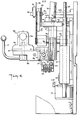
- Fig. 1 illustrates a perspective view of a wafering system according to the invention;
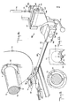
- Fig. 2 illustrates a front view of a part of the wafering system in accordance with the invention;
- Fig. 3 illustrates a side view of the components of Fig. 2 of the watering system in the rest position;
- Fig. 4 illustrates a view similar to Fig. 3 with the arm assembly pivoted from a rest position, the slide moved back and the carriage moved upwardly;
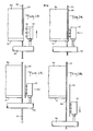
- Fig. 5 illustrates a view taken on line 5-5 of Fig. 2;
- Fig. 6 illustrates a view similar to Fig. 5 with the system in a position spaced from the holding position;
- Fig. 7 illustrates a view taken on line 7-7 of Fig. 2;
- Fig. 8 illustrates a perspective view of a part of the chuck assembly according to the invention;
- Fiq. 9 illustrates a view taken on line 9-9 of Fig. 8;
- Fig. 10 illustrates a view similar to Fig. 9 with a cutting blade near the end of a cutting stroke;
- Fig. 11 illustrates a part perspective view of the head of the chuck assembly pivoted and slid back from the rest position;
- Fig. 12 illustrates a part perspective view of the head raised into a position facing a crystal;
- Fig. 13 illustrates a side view of the position illustrated in Fig. 12;
- Fig. 14 illustrates a side view of the head in a holding position slightly spaced from a wafer being severed;
- Fig. 15 illustrates a position of the head after retrieving a severed wafer during a slide back from the holding position;
- Fig. 16 illustrates a side view of the head during a downward stroke in the carriage in accordance with the invention;
- Fig. 17 illustrates a part perspective view of the head of the chuck assembly and a retrieved wafer in a position for passage through the cutting blade; and
- Fig. 18 illustrates a part perspective view of the head of the chuck assembly with the retrieved wafer in the rest position.
- Referring to Fig. 1, the
wafering system 10 includes an ingot feed means 11, acutting head 12, a wafer retrieval system 13, a take-off conveyor 14, a control box 15 and a table 16. - Referring to Fig. 1, the ingot feed means 11 includes a mounting bracket or
pedestal 17 which is mounted on the table 16 in an offset manner relative to thecutting head 12. In addition, the feed means 11 includes aningot box 18 which is mounted in cantilevered relation to themounting bracket 17 and in alignment with thecutting head 12. Theingot box 18 includes a known means for moving and positioning aningot 19 for cutting purposes. As indicated, the ingot is formed of acrystal 20 of cylindrical shape and amounting beam 21 on which thecrystal 20 is mounted in known manner. For example, thecrystal 20 may be made of silicon while themounting beam 21 is made of graphite. Alternatively, thecrystal 20 may be of any other suitable shape. - Referring to Fig. 8, the
cutting head 12 is of conventional construction and includes arotary cutting blade 22 having abore 23 and acutting edge 24 about thebore 23. The cuttinghead 12 also includes a means (not shown) for moving theblade 22 in a vertical plane transversely of the plane of thecrystal 20. As indicated in Fig. 10, thecutting blade 22 serves to sever awafer 25 of disk-like shape from thecrystal 20. - Referring to Fig. 1 and Fig..8, the wafer retrieval system 13 includes a chuck-
assembly 26 having ahead 27 for engaging a severed wafer (not shown) from thecrystal 20 and means 28 for moving thehead 27 between a rest position (as shown) on one side of theblade 22 and a holding position (not shown) on an opposite side of theblade 22 for holding a severed hafer thereat. - Referring to Fig. 8, the
head 27 is of block-like construction and includes a plurality ofnozzles 29 on one face through which a vacuum can be drawn in order to grip and hold a severed wafer on thehead 27. For example, thenozzles 29 are disposed in three rows with three nozzles in each row. - The means for moving the
head 27 includes anarm 30 having astraight section 31 and abent section 32 on which thehead 27 is mounted in offset relation to thestraight section 31. In addition, thearm 30 includes a bore which communicates at one end with thenozzles 29 and at the opposite end with aspigot 33 on thestraight section 31 to which a suitable vacuum source (not shown) is connected via a flexible tubing (not shown). As shown, thearm 30 is secured in anarm assembly 34 which is pivotally mounted about ahorizontal axis 35. - Referring to Figs. 2, 3 and 8, the
arm assembly 34 includes a mountingblock 36 of split construction in which thearm 30 is securely clamped via clamping bolts 36'. The mountingblock 36 abouts anindex plate 37 which, in turn, is mounted via screws (not shown) to anarm pivot block 38. The mountingblock 36 also carries three positioning detented dowel pins 36'' (only one of which is shown in Fig. 3) each of which is exposed to project into one of three radial slots (not shown) in theindex plate 37 for positioning the mountingblock 36. Theindex plate 37 also includes an arcuate slot 39 (see Fig. 2) in which apin 40 secured in the mountingblock 36 slides. In addition, abolt 42 passes through suitable bores in the mountingblock 36,index plate 37 andpivot block 38 and carries a lockingnut 43 anwasher 44 for fixing of the mountingblock 36 to thepivot block 38 andindex plate 37. A manuallymovable arm 41 is also secured to thebolt 42 such that the mountingblock 36 andarm 30 can be pivoted, for example 90° relative to theindex plate 37 into a position out of the plane of thecutting blade 22 for maintenance purposes. In this position, the dowel pins 36'' ride on theindex plate 37. - The
arm pivot block 38 is of split construction at the upper end, as viewed, for securement via clamping bolts 45' (Fig. 2) to arod 45 which is disposed on the horizontal axis 35 (Fig. 9). A suitable bearing sleeve 38' may also be secured between theblock 38 androd 45 to permit rotation of theblock 38 on therod 45. - Referring to Figs. 2 and 3, the
arm assembly 34 is pivotally mounted via therod 45 in aslide 46. Thisslide 46 includes a pair of dependinglegs 47 in which therod 45 is secured and a connectingpiece 48 which bridges over thelegs 47. The connectingpiece 48 also includes a pair of bores 49 each of which slidably receives ashaft 50 disposed onhorizontal axes 51, 51a (see Fig. 2). In addition, the connectingpiece 48 has an enlargedvertical bore 52 extending through a midsection thereof for purposes as described below. - Referring to Figs. 2 and 3, one
leg 47 of theslide 46 carries a dependingsensor mounting bracket 53 on which a pair of proximity switches 54, 54' are mounted along with aterminal strip 55. - Referring to Figs. 2 and 3, the
shafts 50 on which theslide 46 is slidably mounted are secured in acarriage 56 which is mounted for movement along a vertical axis, as viewed. - The
carriage 56 includes a pair oflegs 57 which are slidably mounted on a pair of fixedupright rods 58 of a base assembly F of the machine. In addition, a horizontal connecting piece 59 (see Fig. 7) interconnects the twolegs 56 and has a vertical bore 60 extending through a mid-point thereof. An upper end of this bore 60 is threaded as indicated in Fig. 3 for purposes as described below. - The
carriage 56 also carries ablock 61 bolted on the connectingpiece 59. Thisblock 61 extends horizontally as viewed in Fig. 3 and has two dependingportions 62 in which bores 63 are provided to fixedly receive therespective shafts 50 via suitable bushings 64 (Fig. 2). In addition, theblock 61 has a centrally located bore 61' of elongated shape (see Fig. 5). - As shown in Fig. 2, a
bracket 64 is secured to a lower end of onecarriage leg 57 via screws 65. Thisbracket 64 carries a magnet 66 for purposes as described below. - Referring to Figs. 3 and 8, in order to actuate the
carriage 56, a means such as amotor 67 is mounted on the base assembly F of the machine and drives a threadedscrew 68 which is threaded into the bore 60 of thecarriage 56. Thus, upon rotation of thescrew 68, thecarriage 56 is moved up or down, depending upon the direction of rotation of thescrew 68. - Referring to Figs. 2 and 3, the
slide 46 carries a bridge-like member 67 which passes over theblock 61 of thecarriage 56 and through which a bore 67' passes. The bridge-like member 67 also carries ablock 69 on the upper surface to which a U-shapedair cylinder base 70 is secured in fixed manner via two screws 70' (Fig. 5). In addition, theair cylinder base 70 has apivot pin 71 secured therein on a horizontal axis while aU-shaped clamp block 72 is pivotally mounted on thepin 71. As indicated in Fig. 3, theclamp block 72 secures anair cylinder 73 to theblock 70 for pivoting about thepivot pin 71. Thisair cylinder 73 has arod 74 which passes through a bore 70'' in theblock 69, the bore 67' in the bridge-like manner 67, the bore 61' in thecarriage piece 59 and thebore 52 in theslide 46 into engagement via a rod end joint 75 with thepivot arm assembly 34. As indicated in Fig. 8, the rod end joint 75 is secured to theblock 38 via a mounting 38'' fixed to theblock 38 at a point spaced above the plane of therod 45. Theair cylinder 73 thus serves as a means for pivoting thepivot arm assembly 34 about theaxis 35 of therod 45. To this end, thecylinder 73 has a spigot 73' which is connected via anair hose 73" to a source of air pressure (not shown). When actuated, thecylinder 73 pushes therod 74 downwardly as viewed in Fig. 2, which thecylinder 73 pivots on thepin 71 and therod 74 swings in the enlarged bore 52 in theslide 46. - Referring to Figs. 3 and 5, an adjusting means 76 is also provided for adjusting the
slide 46 along theshafts 50 of thecarriage 56. - The adjusting means 76 includes a
block front 77 to which aface plate 78 is secured via suitable pins 79. Theblock 77 is bolted to theblock 61 by screws (not shown) and, thus, to thecarriage 56. As indicated in Fig. 3, theblock 61 has a small step 80 in which theblock 77 is received. In addition, anair cylinder 81 has apiston rod 82 secured to a recessed portion of theblock 77 viagrommets 83,washers 84 and alock nut 85. Thecylinder 81, in turn, has an externally threaded stem which passes through a flange 69' of theblock 69 and on which alock nut 86 is threaded to secure thecylinder 81 to theblock 69. - In addition, as indicated in Fig. 5, the
cylinder 81 is coupled via a line 81' to a source of pressurized air (not shown) so that, when actuated, thecylinder 81 moves away from theblock front 77. Likewise, theblock 69 which is secured to thecylinder 81, the bridge-like member 67 and theslide 46 move horizontally relative to theblock front 77 andcarriage 56. - The adjusting means 76 also includes a
bracket assembly 87 which is secured viascrews 88 to theblock 69 and amicrometer assembly 89 for adjustment of the stroke of the cylinder 81 a predetermined amount. As indicated, themicrometer assembly 89 has aU-shaped bracket 90 secured to theblock front 77, apin 91 which is slidably mounted at one end of thebracket 90 and arotatable sleeve 92 which is secured with thepin 91 in a manner as known to effect a calibrated linear movement of thepin 91 upon rotation of thesleeve 92. In addition, adrive shaft 93 which is coupled with thesleeve 92 via adowel pin 94 is journalled in the block front 77 (Fig. 3) and is driven via agear 94 thereon, achain 95 and adrive gear 96. Thedrive gear 96 is fixed to ashaft 97 which is rotatably mounted in theblock front 77 and to which amanual knob 98 is secured. As indicated in Fig. 3, theknob 98 is located to the outside of theface plate 78 and theshaft 97 is suitably coupled to acounter 99. - As shown in Fig. 5, the
pin 91 of themicrometer assembly 89 engages against astop 100 which is secured to abracket 101 which, in turn, is secured as by a screw (not shown) to thebracket 87. - Referring to Figs. 2 and 3, the frame F also carries a
tube 102 through which various electrical lines for the system pass. Thetube 102 is secured at an upper end in abracket 103 which serves as a vertical carriage stop and which is bolted to the frame F. At the lower end, thetube 102 is secured in a holder 104 (see Fig. 3) which mounts themotor 67 as well as a sensor bracket (not shown) and a bumper (not shown) which functions as a lower carriage stop. Theholder 104 also carries aterminal strip 105. In like manner, the frame F also carries a further terminal strip 106 (see Fig. 2). - The
wafering system 10 is also provided with various means to sense the position of the various movable components and, thus, insure an accurate sequencing of the movements. To this end, as shown in Fig. 8, thepivotal arm assembly 34 has amagnet 107 on thepivot block 38 and amagnet 108 on the mounting 38''. Themagnet 107 cooperates with the left-hand switch 54, as viewed in Fig. 3, to indicate when thearm assembly 34 is in a rest or down position while themagnet 108 cooperates with the righthand switch 54' to indicate when thearm assembly 34 is in a fully pivoted position as in Fig. 4. Likewise, the magnet 66 on thecarriage leg 57 cooperates with a proximity switch (not shown) on themotor holder 104 to indicate when thecarriage 56 is in a down or rest position. - Suitable bumpers (not shown) may also be used to ensure stopping of a movable component at the terminal positions of each. For example, as shown in Fig. 2 a
stop bar 109 is secured across theslide 46 viascrews 110 to limit a return pivot action of thepivotal arm assembly 34. - Referring to Fig. 6, in order to set the watering system 1-0 for a retrieving operation, the
slide 46 is moved so as to space thestop 100 from themicrometer pin 91. Theknob 98 is then turned to dial in a set amount on thecounter 99 representative of the thickness of wafer required e.g. 0.015 inches and a small gap, e.g. 0.010 inches. Theslide 46 is then returned to the rest position with thestop 100 abutting thepin 91. - Referring to Figs. 11 to 18, during operation, the wafering system operates so that the
blade 22 cuts through thecrystal 20 toward a point short of complete severance (Fig. 11). At this time, thearm assembly 30 is pivoted from the rest position illustrated in Fig. 8 by an amount sufficient to pass the head 2 7 through theopening 23 in the blade 22 (Fig. 11) while theslide 46 is simultaneously moved back. Thereafter, as theblade 22 continues to rotate, thehead 27 is raised vertically as shown in Figs. 12 and 13. In this latter position, thehead 27 is spaced from the wafer being severed from the crystal. Next thehead 27 is moved toward the wafer as governed by the dialed-in gap so that thenozzles 29 are spaced from the wafer 25 (Fig. 14). At this time, a limit switch (not shown) then turns on a vacuum so that thewafer 25 is gripped. However, the blade has not yet cut through theentire mounting beam 21. Continued rotation of theblade 22 causes complete severing of thewafer 25. Thehead 27 is then moved back away from thecrystal 20 as indicated in Fig. 15 to move thewafer 25 clear of thecrystal 20. Coincidentally, thecrystal 20 can be moved away from theblade 22 by a back-off mechanism (not shown). Next, as indicated in Figs. 16 and 17, thehead 27 is moved vertically downwardly so that thewafer 25 is located within the plane of theopening 23 in the blade. Next, thearm assembly 30 is again pivoted to bring thehead 27 into the rest position (Fig. 18). In this position, thewafer 25 is located above the take-offconveyor 14. The vacuum to thearm assembly 30 can then be deactivated so that thewafer 25 is gently dropped onto the take-offconveyor 14. Thecutting blade 22 then returns to a starting position ready to repeat a cutting cycle. - As indicated in Fig. 1, the take-off
conveyor 14 may be provided with a suitable cassette holder 111 in which a plurality of severedwafers 25 can be sequentially stacked for subsequent use and/or shipment. - When a wafer is to be retrieved, the
air cylinder 81 is actuated to move theslide 46 away from theface plate 78 andair cylinder 73 is actuated simultaneously to pivot thearm assembly 34 into the position illustrated in Fig. 4. During this time, thecylinder 73 pivots about thepivot pin 71 into an angular position. Next, themotor 67 is actuated to raise thecarriage 56 into an upper position (see Figs. 4 and 13). Theair cylinder 81 is then deactivated to move theslide 46 relative to thecarriage 56, for example to the left as viewed in Fig. 4. In this position, thestop 100 moves against thepin 91 of the micrometer assembly 89 (see Figs. 5 and 14). In this holding position, suction is drawn on the head so that thehead 27 is able to remove and hold a severedwafer 25 against thenozzles 29 under a suction force. For example, thehead 27 may hold a fourinch diameter wafer 25 of a thickness of about 0.010 inch to 0.015 inch in a vertical plane with a force exceeding 5 to 10 pounds lateral pull. In this respect, thewafer 25 can be transferred from theingot 19 to thevacuum head 27 with a gap setting of, for example, 0.010 inch. A reverse sequence of steps is then carried out to bring thewafer 25 through thecutting blade 22 into the rest position illustrated in Fig. 18. - The invention thus provides a wafering system in which a severed wafer can be quickly and reliably retrieved. Further, the invention provides a wafering assembly in which an operator can view the various working parts from a single working position.
- The invention further provides a chuck assembly wherein use is made of a single head for retrieving a severed wafer from a crystal and for transporting the wafer onto a take-off conveyor for subsequent processing.
- Of note, once the severed wafer has been passed through the rotary blade, the blade can be returned for a subsequent severing operation. As the time of moving the severed wafer through the blade is relatively minimal, a quick return of the blade occurs.
- The wafering system may also be used to sever the ends of the
nozzles 29 while mounted on thehead 27 by using the slow vertical motion of thecarriage 56 with thearm assembly 34 pivoted and moved forward against thepin 91 and with the counter at a preset zero position. This ensures a true plane of the nozzle ends parallel to the face of a wafer being severed in a subsequent operation. - Referring to Fig. 1, the control box 15 contains various controls and a programming means for programming the movement of the
motor 67 for reciprocating thecarriage 56, theair cylinder 81 for reciprocating theslide 46 and theair cylinder 73 for pivoting thearm assembly 34. The programming means can be of conventional construction and need not be further described, - Further, the various components of the system can be provided with bumpers of resilient nature to effect stoppage of a movable component in a given position.
Claims (10)
Applications Claiming Priority (2)
| Application Number | Priority Date | Filing Date | Title |
|---|---|---|---|
| US320097 | 1981-11-10 | ||
| US06320097 US4420909B2 (en) | 1981-11-10 | 1981-11-10 | Wafering system |
Publications (3)
| Publication Number | Publication Date |
|---|---|
| EP0079744A2 true EP0079744A2 (en) | 1983-05-25 |
| EP0079744A3 EP0079744A3 (en) | 1984-09-05 |
| EP0079744B1 EP0079744B1 (en) | 1986-09-17 |
Family
ID=23244880
Family Applications (1)
| Application Number | Title | Priority Date | Filing Date |
|---|---|---|---|
| EP82305945A Expired EP0079744B1 (en) | 1981-11-10 | 1982-11-09 | Clutch assembly for removing a severed wafer from an ingot |
Country Status (4)
| Country | Link |
|---|---|
| US (1) | US4420909B2 (en) |
| EP (1) | EP0079744B1 (en) |
| JP (3) | JPS5887830A (en) |
| DE (1) | DE3273372D1 (en) |
Cited By (2)
| Publication number | Priority date | Publication date | Assignee | Title |
|---|---|---|---|---|
| EP0242489A1 (en) * | 1986-04-17 | 1987-10-28 | Maschinenfabrik Meyer & Burger AG | Process for separating a rod into segments, cutter grinding machine for carrying out this process, and its use |
| FR2622820A1 (en) * | 1987-11-05 | 1989-05-12 | Mueller Georg Nuernberg | METHOD AND DEVICE FOR MANUFACTURING PELLETS HAVING AT LEAST ONE FLAT SURFACE |
Families Citing this family (27)
| Publication number | Priority date | Publication date | Assignee | Title |
|---|---|---|---|---|
| US4602854A (en) * | 1985-02-25 | 1986-07-29 | At&T Technologies, Inc. | Polyhedral ring mirrors and their manufacture |
| JPS6213305A (en) * | 1985-07-12 | 1987-01-22 | 株式会社日立製作所 | Work turn type cutting method and device thereof |
| US4667650A (en) * | 1985-11-21 | 1987-05-26 | Pq Corporation | Mounting beam for preparing wafers |
| US4903681A (en) * | 1987-02-24 | 1990-02-27 | Tokyo Seimitus Co., Ltd. | Method and apparatus for cutting a cylindrical material |
| US4899719A (en) * | 1987-07-31 | 1990-02-13 | Mitsubishi Kinsoku Kabushiki Kaisha | Apparatus for collecting wafers |
| JP2623604B2 (en) * | 1987-10-21 | 1997-06-25 | 三菱マテリアル株式会社 | Slicer cutting feeder |
| US4819387A (en) * | 1987-12-16 | 1989-04-11 | Motorola, Inc. | Method of slicing semiconductor crystal |
| US5025593A (en) * | 1988-01-18 | 1991-06-25 | Mazda Motor Corporation | Slicing machine and control method thereof |
| US5111622A (en) * | 1989-05-18 | 1992-05-12 | Silicon Technology Corporation | Slicing and grinding system for a wafer slicing machine |
| US4974578A (en) * | 1989-08-17 | 1990-12-04 | Silicon Technology Corporation | Housing for mounting a spindle of an internal diameter saw blade |
| JPH0695504B2 (en) * | 1989-10-31 | 1994-11-24 | 直江津電子工業株式会社 | Wafer supply / collection device in a wafer single-wafer inner peripheral blade two-division cutting device |
| US5189843A (en) * | 1990-08-30 | 1993-03-02 | Silicon Technology Corporation | Wafer slicing and grinding machine and a method of slicing and grinding wafers |
| US5148797A (en) * | 1991-03-14 | 1992-09-22 | Silicon Technology Corporation | Mounting for an internal diameter saw blade |
| US5243960A (en) * | 1991-12-31 | 1993-09-14 | Stone Panels, Inc. | Apparatus for cutting stone laminate panels |
| US5427644A (en) * | 1993-01-11 | 1995-06-27 | Tokyo Seimitsu Co., Ltd. | Method of manufacturing semiconductor wafer and system therefor |
| JP2823493B2 (en) * | 1993-01-18 | 1998-11-11 | トーヨーエイテック株式会社 | Method and apparatus for detecting blade deflection of slicing device and blade deflection control device |
| JP2943673B2 (en) * | 1995-10-31 | 1999-08-30 | 日本電気株式会社 | Apparatus and method for manufacturing semiconductor substrate |
| EP0964333A1 (en) | 1998-06-10 | 1999-12-15 | Sun Microsystems, Inc. | Resource management |
| DE69831857T2 (en) * | 1998-06-10 | 2006-06-14 | Sun Microsystems Inc | Method and device for scheduling processes for resource allocation |
| DE19950068B4 (en) * | 1999-10-16 | 2006-03-02 | Schmid Technology Systems Gmbh | Method and device for separating and detaching substrate disks |
| KR100889242B1 (en) * | 2006-05-15 | 2009-03-17 | 주식회사 엘지화학 | BMS Having Waterproof Function |
| DE102009047027B3 (en) * | 2009-11-23 | 2011-07-28 | J. Schmalz GmbH, 72293 | Device for producing material disks |
| CN105374730B (en) * | 2015-10-23 | 2018-03-27 | 河北晶龙阳光设备有限公司 | A kind of manipulator and its Double-head transporter for turning basket for solar battery sheet |
| CN105500541B (en) * | 2015-12-31 | 2017-09-29 | 天津朗誉科技发展有限公司 | A kind of silicon rod crystal overturns system |
| JP6938087B2 (en) * | 2017-09-21 | 2021-09-22 | 株式会社ディスコ | Cutting blade mounting mechanism |
| US20230042659A1 (en) * | 2021-08-03 | 2023-02-09 | Meta Platforms, Inc. | Complex photonics circuit fabrication |
| CN115050680B (en) * | 2022-08-16 | 2022-10-28 | 江苏邑文微电子科技有限公司 | Quick positioning device and method for wafer box |
Citations (2)
| Publication number | Priority date | Publication date | Assignee | Title |
|---|---|---|---|---|
| DE1148480B (en) * | 1961-07-13 | 1963-05-09 | Siemens Ag | Device for sawing bodies made of Sproedem material into wafers, in particular rod-shaped semiconductor crystals |
| DE2052896A1 (en) * | 1969-10-29 | 1971-05-06 | Caphn Engineering Co Ltd , Ipswich, Suffolk (Großbritannien) | Cutting device |
Family Cites Families (8)
| Publication number | Priority date | Publication date | Assignee | Title |
|---|---|---|---|---|
| US3039235A (en) * | 1961-01-31 | 1962-06-19 | Hamco Mach & Elect Co | Cutting apparatus |
| US3577861A (en) * | 1969-04-07 | 1971-05-11 | Kayex Corp | Transfer device for cutting apparatus |
| JPS5029171A (en) * | 1973-07-17 | 1975-03-25 | ||
| JPS51126033A (en) * | 1975-04-25 | 1976-11-02 | Hitachi Ltd | Wafer collection device for slicer |
| JPS5244671A (en) * | 1975-10-06 | 1977-04-07 | Mitsubishi Electric Corp | Circuit for detecting quantity of electricity |
| JPS5632507Y2 (en) * | 1976-07-30 | 1981-08-03 | ||
| JPS53139686U (en) * | 1977-04-09 | 1978-11-04 | ||
| JPS5646529A (en) * | 1979-09-21 | 1981-04-27 | Citizen Watch Co Ltd | Wafer chuck |
-
1981
- 1981-11-10 US US06320097 patent/US4420909B2/en not_active Expired - Lifetime
-
1982
- 1982-11-09 EP EP82305945A patent/EP0079744B1/en not_active Expired
- 1982-11-09 DE DE8282305945T patent/DE3273372D1/en not_active Expired
- 1982-11-10 JP JP57198318A patent/JPS5887830A/en active Granted
-
1989
- 1989-03-06 JP JP1053587A patent/JPH01264806A/en active Pending
-
1991
- 1991-12-24 JP JP35708891A patent/JP2601594B2/en not_active Expired - Lifetime
Patent Citations (2)
| Publication number | Priority date | Publication date | Assignee | Title |
|---|---|---|---|---|
| DE1148480B (en) * | 1961-07-13 | 1963-05-09 | Siemens Ag | Device for sawing bodies made of Sproedem material into wafers, in particular rod-shaped semiconductor crystals |
| DE2052896A1 (en) * | 1969-10-29 | 1971-05-06 | Caphn Engineering Co Ltd , Ipswich, Suffolk (Großbritannien) | Cutting device |
Cited By (3)
| Publication number | Priority date | Publication date | Assignee | Title |
|---|---|---|---|---|
| EP0242489A1 (en) * | 1986-04-17 | 1987-10-28 | Maschinenfabrik Meyer & Burger AG | Process for separating a rod into segments, cutter grinding machine for carrying out this process, and its use |
| US4771759A (en) * | 1986-04-17 | 1988-09-20 | Meyer + Burger Ag | Method for severing a rod in slices, slicing machine for carrying out the method and use of the slicing machine |
| FR2622820A1 (en) * | 1987-11-05 | 1989-05-12 | Mueller Georg Nuernberg | METHOD AND DEVICE FOR MANUFACTURING PELLETS HAVING AT LEAST ONE FLAT SURFACE |
Also Published As
| Publication number | Publication date |
|---|---|
| EP0079744A3 (en) | 1984-09-05 |
| EP0079744B1 (en) | 1986-09-17 |
| JP2601594B2 (en) | 1997-04-16 |
| US4420909A (en) | 1983-12-20 |
| JPH01264806A (en) | 1989-10-23 |
| US4420909B1 (en) | 1989-11-14 |
| DE3273372D1 (en) | 1986-10-23 |
| JPH0247324B2 (en) | 1990-10-19 |
| US4420909B2 (en) | 1997-06-10 |
| JPH06143250A (en) | 1994-05-24 |
| JPS5887830A (en) | 1983-05-25 |
Similar Documents
| Publication | Publication Date | Title |
|---|---|---|
| EP0079744B1 (en) | Clutch assembly for removing a severed wafer from an ingot | |
| US3921472A (en) | Rotary wire stripper | |
| US4472218A (en) | Removing articles from an adhesive web | |
| US3855738A (en) | Crystal indexing fixture | |
| US3662733A (en) | Annular cutting apparatus with work removal means | |
| CN221270066U (en) | Laser plate cutting machine | |
| US4321848A (en) | Cylindrical member processing apparatus | |
| JPH10180512A (en) | Boring machine | |
| JPH02111211A (en) | Apparatus for cutting and feeding wire segment and removing insulation from wire segment | |
| US20030153447A1 (en) | Tag attaching apparatus | |
| US5367836A (en) | Automatic drill loader | |
| US5062621A (en) | Zero diameter locator post | |
| US4441386A (en) | Wire cutter and stripper apparatus | |
| US4455044A (en) | Tool for picking up and inserting different length bolts | |
| US4182206A (en) | Cylindrical member processing apparatus | |
| CN214561565U (en) | Preferred push rod fine cutting saw | |
| KR0135294B1 (en) | Automatic dendritic silicon web separation machine | |
| US5134912A (en) | Tab tape singulation apparatus and method | |
| US3271904A (en) | Precision wire severing apparatus | |
| CN215392813U (en) | Forming device is used in tubular metal resonator processing | |
| CN208147387U (en) | A kind of part processing unit (plant) | |
| JPH05253702A (en) | Bar feeder | |
| CN220065423U (en) | Multi-specification wire rod sleeve penetrating, winding and encapsulation integrated machine for electronic transformer | |
| CN217493555U (en) | Cutting device | |
| CN216680488U (en) | Automatic pipe cutting device |
Legal Events
| Date | Code | Title | Description |
|---|---|---|---|
| PUAI | Public reference made under article 153(3) epc to a published international application that has entered the european phase |
Free format text: ORIGINAL CODE: 0009012 |
|
| AK | Designated contracting states |
Designated state(s): CH DE FR GB IT LI |
|
| PUAL | Search report despatched |
Free format text: ORIGINAL CODE: 0009013 |
|
| AK | Designated contracting states |
Designated state(s): CH DE FR GB IT LI |
|
| 17P | Request for examination filed |
Effective date: 19841115 |
|
| GRAA | (expected) grant |
Free format text: ORIGINAL CODE: 0009210 |
|
| AK | Designated contracting states |
Kind code of ref document: B1 Designated state(s): CH DE FR GB IT LI |
|
| PG25 | Lapsed in a contracting state [announced via postgrant information from national office to epo] |
Ref country code: IT Free format text: LAPSE BECAUSE OF FAILURE TO SUBMIT A TRANSLATION OF THE DESCRIPTION OR TO PAY THE FEE WITHIN THE PRESCRIBED TIME-LIMIT;WARNING: LAPSES OF ITALIAN PATENTS WITH EFFECTIVE DATE BEFORE 2007 MAY HAVE OCCURRED AT ANY TIME BEFORE 2007. THE CORRECT EFFECTIVE DATE MAY BE DIFFERENT FROM THE ONE RECORDED. Effective date: 19860917 |
|
| REF | Corresponds to: |
Ref document number: 3273372 Country of ref document: DE Date of ref document: 19861023 |
|
| ET | Fr: translation filed | ||
| PLBE | No opposition filed within time limit |
Free format text: ORIGINAL CODE: 0009261 |
|
| STAA | Information on the status of an ep patent application or granted ep patent |
Free format text: STATUS: NO OPPOSITION FILED WITHIN TIME LIMIT |
|
| 26N | No opposition filed | ||
| REG | Reference to a national code |
Ref country code: GB Ref legal event code: 727 |
|
| REG | Reference to a national code |
Ref country code: GB Ref legal event code: 727A |
|
| REG | Reference to a national code |
Ref country code: GB Ref legal event code: 727B |
|
| REG | Reference to a national code |
Ref country code: GB Ref legal event code: SP |
|
| PGFP | Annual fee paid to national office [announced via postgrant information from national office to epo] |
Ref country code: GB Payment date: 19951031 Year of fee payment: 14 |
|
| PGFP | Annual fee paid to national office [announced via postgrant information from national office to epo] |
Ref country code: FR Payment date: 19951109 Year of fee payment: 14 |
|
| PGFP | Annual fee paid to national office [announced via postgrant information from national office to epo] |
Ref country code: DE Payment date: 19951113 Year of fee payment: 14 |
|
| PGFP | Annual fee paid to national office [announced via postgrant information from national office to epo] |
Ref country code: CH Payment date: 19951122 Year of fee payment: 14 |
|
| PG25 | Lapsed in a contracting state [announced via postgrant information from national office to epo] |
Ref country code: GB Effective date: 19961109 |
|
| PG25 | Lapsed in a contracting state [announced via postgrant information from national office to epo] |
Ref country code: LI Effective date: 19961130 Ref country code: CH Effective date: 19961130 |
|
| GBPC | Gb: european patent ceased through non-payment of renewal fee |
Effective date: 19961109 |
|
| REG | Reference to a national code |
Ref country code: CH Ref legal event code: PL |
|
| PG25 | Lapsed in a contracting state [announced via postgrant information from national office to epo] |
Ref country code: FR Effective date: 19970731 |
|
| PG25 | Lapsed in a contracting state [announced via postgrant information from national office to epo] |
Ref country code: DE Effective date: 19970801 |
|
| REG | Reference to a national code |
Ref country code: FR Ref legal event code: ST |