EP0079695B1 - Maschine zur fortschreitenden Bearbeitung entlang den Randbereichen von Schuhböden - Google Patents
Maschine zur fortschreitenden Bearbeitung entlang den Randbereichen von Schuhböden Download PDFInfo
- Publication number
- EP0079695B1 EP0079695B1 EP82305645A EP82305645A EP0079695B1 EP 0079695 B1 EP0079695 B1 EP 0079695B1 EP 82305645 A EP82305645 A EP 82305645A EP 82305645 A EP82305645 A EP 82305645A EP 0079695 B1 EP0079695 B1 EP 0079695B1
- Authority
- EP
- European Patent Office
- Prior art keywords
- tool
- shoe
- tool carrier
- heightwise
- relative
- Prior art date
- Legal status (The legal status is an assumption and is not a legal conclusion. Google has not performed a legal analysis and makes no representation as to the accuracy of the status listed.)
- Expired
Links
Images
Classifications
-
- A—HUMAN NECESSITIES
- A43—FOOTWEAR
- A43D—MACHINES, TOOLS, EQUIPMENT OR METHODS FOR MANUFACTURING OR REPAIRING FOOTWEAR
- A43D119/00—Driving or controlling mechanisms of shoe machines; Frames for shoe machines
-
- A—HUMAN NECESSITIES
- A43—FOOTWEAR
- A43D—MACHINES, TOOLS, EQUIPMENT OR METHODS FOR MANUFACTURING OR REPAIRING FOOTWEAR
- A43D37/00—Machines for roughening soles or other shoe parts preparatory to gluing
Definitions
- This invention is concerned with a machine suitable for operating progressively along marginal portions of shoe bottoms, comprising a shoe support, a tool carrier, means for effecting relative movement, both lengthwise and widthwise of the bottom of a shoe supported by the shoe support, between the shoe support and the tool carrier, and means for controlling the heightwise position of the tool carrier relative to the shoe support, as relative lengthwise and widthwise movement is caused to take place therebetween, so that, in an operating mode of the machine, the tool carrier can follow a pre-determined-path, determined according to the contour of the shoe bottom being operated upon, relative to the shoe support, and a tool carried by the tool carrier can thus be caused to operate progressively along a marginal portion of the bottom of a shoe supported by the shoe support, wherein the tool is mounted on the tool carrier for limited movement relative thereto in a direction extending heightwise relative to the shoe support.
- GB-A-1071761 One such machine is disclosed in GB-A-1071761.
- a three-dimensional template is located in a fixed relationship with the bottom of a shoe supported by the shoe support; and the shoe support is caused to move lengthwise of the shoe bottom to carry the bottom of a shoe supported thereby past two tools each supported by a tool carrier, each tool carrier having associated therewith template following means which engage with opposite side portions of the template and thus cause the tools to be moved widthwise and heightwise of the path of movement of the shoe support, as the shoe support is thus moved.
- each tool is mounted for pivotal movement, about an axis extending widthwise of the shoe bottom, stop means being provided for limiting the downward movement of each tool towards the shoe bottom.
- the three-dimensional template selected to suit the shoe bottom being operated upon, thus guides the tools, arranged in tandem relationship, along opposite side portions of the shoe bottom during relative lengthwise movement between the shoe support and tool carrier, any irregularities in the shoe bottom, as compared with the contour of the template, being accommodated by the facility for pivotal movement of the tool on the carrier.
- a disadvantage of this arrangement resides in that a different template is required for each style and size of shoe, and indeed in each style and size separate templates are required for left and right shoes.
- The-shoe bottom contour is of course a relatively complex one, and thus the use of a three-dimensional template is advantageous to the extent that it can be relatively easily reproduced direct from the shoe bottom, without the need for any complicated calculations. Because the problems referred to above are considered to outweigh this one advantage of manufacture, however, there has been a move away from such three-dimensional templates: see e.g. GB-A-1137254, in which flat (i.e. two-dimensional) templates are used.
- This change from three-dimensional templates has meant that the machine can itself be used in the manufacture of templates, the arrangement being such that, with a blank template carried by the template supporting means, a tool is moved relative to the shoe bottom by the operator, along a path determined by him, and an associated scribing tool, replacing the template follower, is caused to track over the surface of the blank template and score an appropriate line thereon.
- the template can thereafter be cut along the line to provide the desired shape.
- Such a procedure is also referred to in GB-A-1137254.
- the invention thus provides a machine suitable for operating progressively along marginal portions of shoe bottoms, comprising a shoe support, a tool carrier, means for effecting relative movement, both lengthwise and widthwise of the bottom of a shoe supported by the shoe support, between the shoe support and the tool carrier, and means for controlling the heightwise position of the tool carrier relative to the shoe support, as relative lengthwise and widthwise movement is caused to take place therebetween, so that, in an operating mode of the machine, the tool carrier can follow a predetermined path, determined according to the contour of the shoe bottom being operated upon, relative to the shoe support, and a tool carried by the tool carrier can thus be caused to operate progressively along a marginal portion of the bottom of a shoe supported by the shoe support, wherein the tool is mounted on the tool carrier for limited movement relative thereto, in a direction extending heightwise relative to the shoe support, characterised in that the means for effecting relative lengthwise and widthwise movement between the shoe support and tool carrier comprises first and second numerically controlled motors (as herein defined) and the means for controlling the height
- number of controlled motor where used herein is to be understood as indicating a motor the operation of which is controlled by control signals supplied thereto in accordance with stored information appropriate to a desired operation.
- motors are stepping motors and d.c. servomotors.
- the resilient means is effective to urge the tool in a direction towards the shoe support. Furthermore, it is desirable that the pressure applied to a shoe bottom by the tool, as it operates progressively along a marginal portion of such shoe bottom, is controlled. To this end, therefore, in accordance with the invention, preferably also, in the operating mode of the machine, the tool is displaced, against the action of the resilient means, out of its defined heightwise position in relation to the tool carrier and thus the pressure applied thereby is controlled by the resilient means.
- the tool is a roughing tool
- such a system of transposition may be undesirable in that, at the start of the operating cycle, the tool would, as it approaches the shoe bottom but is not yet in engagement therewith, be disposed in its defined heightwise position and thus the shoe bottom engaging portion of its operating surface would be disposed below the level of the shoe bottom, with a result that the shoe upper may be roughed above its feather line as the tool engages the side of the shoe and is moved over its edge on to the shoe bottom.
- each selected point is determined in relation to the defined heightwise position of the tool, the tool carrier being thereafter moved heightwise through a distance to displace the tool from its defined heightwise position prior to the co-ordinate axis values of the selected point being digitised.
- such displacement is arranged not to take place at the first selected point, so that, e.g. in the case of a roughing tool, the tool is positioned directly at the height of the shoe bottom at the start of roughing.
- Such displacement may be effected under the direct control of the operator.
- the procedure lends itself to automatic execution.
- the resilient means may be fluid pressure operated and may further comprise variable pressure regulating means, the arrangement being such that the pressure applied to a shoe bottom by the tool is thus controlled by the pressure regulating means.
- means may be provided whereby the pressure controlled by said regulating means, and thus also the pressure applied as aforesaid to the shoe bottom, can be varied during the progressive operation of the tool along the marginal portion of the shoe bottom as aforesaid.
- changes in pressure may be programmed into the computer control means at the same time as digitising takes place.
- the sensing means referred to may be arranged to prevent digitising from taking place unless the tool is in its defined heightwise position.
- the sensing means causes indicator means to be operated whereby a.signal is provided, visible by the operator, when the tool is in its defined heightwise position and when moved therefrom. In this way, the operator can more readily ascertain when the tool has moved into its defined position.
- the sensing means may be of any conventional type, e.g. fluidic.
- the tool is a rotary tool, more especially a radial wire roughing brush, said tool being carried on an arm which is supported on the tool carrier for pivotal movement about an axis extending generally lengthwise of the shoe bottom and on which the resilient means is arranged to act, belt drive means being provided for rotating the tool, including a pulley mounted for rotation about said axis.
- grinding means may be provided, as is. conventional, whereby the operating surface of the tool can be ground.
- means is also provided for shifting the defined heightwise position of the tool in relation to the tool carrier through a predetermined distance each time a grinding operation takes place.
- the shifting means may conveniently also comprise a numerically controlled motor (as herein defined).
- the tool may be urged into its said defined heightwise position, to which end increased pressure is applied to and acts upon the resilient means, such pressure being sufficient to resist any counter-pressure as the grinding means is urged against the operating surface of the tool.
- the tool may be moved during the grinding operation into a second defined heightwise position spaced from said first-mentioned defined heightwise position.
- the tool carrier is mounted for pivotal movement about an axis extending widthwise of the shoe bottom, the tool being so arranged that said axis extends tangentially, or substantially so, to the shoe bottom engaging portion of its operating surface, when the tool is in contact with the shoe bottom being operated upon.
- means including a numerically controlled motor (as herein defined), is provided for effecting pivotal movement of the tool carrier about said axis as the tool is caused to operate progressively along the marginal portion of the bottom of a shoe, said motor also operating under the control of computer control means in response to drive signals generated and supplied thereto by said computer control means in accordance with a programmed instruction.
- the machine now to be described is generally similar, except as hereinafter described, to the machine described in our co-pending EP-A--0 043 645 being a machine for use in performing a roughing operation progressively along marginal portions of shoe bottoms.
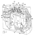
- the machine thus comprises a base 10 supporting on brackets 12 two pivot shafts 14, each in turn carrying a support 16 for a shoe support 18.
- Each shoe support 18 can support a shoe S, bottom uppermost, with the toe end thereof facing towards the front of the machine, i.e. towards the operator.
- the base 10 supports a support column structure 22 carrying a casting on which tool supporting means generally designated 26 is carried the tool supporting.
- a bifurcated arm 30 supported, for pivotal movement about a horizontal axis, between upstanding lugs 32 forming part of a support casting 34, the latter casting itself being supported for pivotal movement about a vertical axis.
- a first numerically controlled motor constituted by a stepping motor 144
- a second numerically controlled motor constituted by a second stepping motor 84
- a drive arrangement generally designated 70.
- a third numerically controlled motor (as herein defined), constituted by a stepping motor (not shown, but identified by reference numeral 122 in the aforementioned EPC Patent Specification), is provided, acting on a rearwardly extending portion 102 of the arm 30.
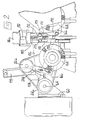
- the arm 30 supports a transversely extending bridge member at opposite ends of which are provided forwardly projecting arms 152, between which is carried, on fulcrum pins 154, a generally U-shaped tool carrier comprising a cross-beam 156, two bevelled gear housings 158, arranged one at either end of the cross-beam, and two forwardly projecting arms 160.
- a shaft 164 Projecting forwardly from each housing 158 is a shaft 164 on which an inwardly extending transverse support arm 166 is pivotally mounted, each arm 166 carrying a rotary radial wire roughing brush 168.
- each support arm 166 has a link 170 pivotally connected thereto, the opposite end of each link 170 having formed therein a slot 171 in which is received a pin 173, whereby pivotal movement of the arm 166 about the shaft 164 is limited.
- resilient means constituted by a pneumatically controlled piston-and-cylinder arrangement 175, is provided a piston rod 177 of which is pivotally connected to the arm 166, said arrangement 175 being effective, when actuated, to urge the link downwardly relative to said pin.
- Each pin 173 is mounted in a block 172, itself mounted for limited heightwise sliding movement on a front face of the cross-beam 156.
- the block 172 threadedly receives a threaded shaft 180 coupled, via a universal coupling 182, to the output drive shaft of a numerically controlled motor (as herein defined), constituted by a stepping motor 186, supported on the cross-beam 156.
- a numerically controlled motor as herein defined
- Operation of the stepping motor 186 is thus effective to cause the block 172 to be moved heightwise relative to the cross-beam 156, thus to shift the defined heightwise position of each tool 168, as determined by engagement between each pin 173 and the upper end of its associated slot 171.
- the distance through which such shifting takes place is pre-determined.
- the stepping motor 186 is operated each time a brush grinding operation takes place, as will be referred to hereinafter.
- the tool carrier is mounted for pivotal movement on the fulcrum pins 154, thus to cause the roughing brushes 168 to be tilted bodily therewith about the axis of the fulcrum pins 154.
- the plane of each radial brush can be maintained perpendicular, or substantially so, to the plane of the area of the shoe bottom at the time being operated upon.
- a further numerically controlled motor (as herein defined), constituted by a. stepping motor 232, is provided, which acts through a rod 204 which in turn is pivotally connected to an upstanding bracket on the cross-beam 156.
- the shoe bottom engaging portion of the operating surface of each tool is maintained, by successive grinding operations, such that it lies tangentially, or substantially so, to the plane in which the axis of the fulcrum pins 154 is disposed, when the brushes are in contact with the shoe bottom.
- the pivotal movement of the brushes about said axis does not significantly affect the position of the shoe bottom engaging portion of the operating surface of each tool lengthwise, heightwise and widthwise of the shoe bottom.
- the roughing brushes 168 are caused to rotate in contrary directions such that each brush, as it is caused to operate progressively along a marginal portion of the shoe bottom, effects an inwiping action on such marginal portion.
- an electric motor 300 mounted on the base 10 of the machine is provided, which operates through a system of drive belts and drive pulleys, as described in greater detail in the aforementioned EPC Patent Specification.
- Said system comprises, for each brush, a pulley 246, mounted on the shaft 164, said pulley being operatively connected to the spindle of the roughing brush 168 by a drive belt 244, over a tensioning pulley 266 carried on the arm 166.
- the machine in accordance with the invention is computer-controlled, the computer having a storage memory for storing digitised information relating to a number of selected styles of shoe bottom to be operated upon, the operator selecting the appropriate style for the particular shoe to be operated upon the next cycle of operation; such selection may be through a keyboard (not shown) of the computer.
- the digitised information may be stored on a suitable information-carrying medium, e.g. magnetic tape. In such a case, selection of a given style will of course require the appropriate medium to be placed in a reader of the computer.
- programmed instruction when used herein is intended to include digitised information particular to a given shoe style, regardless of the manner of its storage.
- the computer is effective, in response to the programmed instruction selected, to cause the tool carrier to follow a predetermined path with reference to three co-ordinate axes relative to the shoe support.
- the computer supplies drive signals, in the form of control pulses, to the appropriate stepping motor 144, whereby its associated shoe support 18 is caused to move the shoe bottom beneath the brushes 168, while simultaneously drive signals, also in the form of control pulses, are supplied to the second and third stepping motors for effecting movement of the tool support both widthwise and heightwise of the path of lengthwise movement of the shoe support.
- the computer may supply drive signals, in the form of control pulses, to the stepping motor 232, whereby the tool support is caused to pivot about the axis of the fulcrum pins 154 as aforementioned.
- control pulses are generated and supplied thereto in accordance with a programmed instruction, including digitised co-ordinate axis values, using three co-ordinate axes, for a plurality of successive selected points along the marginal portion to be operated upon, such digitised information being stored in the memory of the computer.
- the various stepping motors of the machine and also the computer control means thereof may also be utilised for determining the operative path of the tool carrier in relation to the shoe support.
- a model shoe is placed in one of the shoe supports 18 and relative lengthwise, widthwise and heightwise movement is effected between the tool carrier and the shoe support, spaced points of contact being selected between a brush 168 carried by the tool carrier and the shoe bottom supported by the shoe support, and the co-ordinate axis values of each such selected point being caused to be digitised using the computer control means and to be thereafter stored in the memory of such computer.
- the method used for determining the path of the tool carrier relative to the shoe support using the machine in accordance with the invention is generally similar, except as hereinafter described, to the method described in our co-pending EP-A-0 041 808.
- the machine also comprises operator controlled means, including a manually operable control device, generally as described in the last-mentioned Patent Specification, for effecting relative lengthwise, widthwise and heightwise movement between the tool carrier and the shoe support.
- each tool 168 may "float" heightwise in relation to the carrier, thus to accommodate any irregularities in the shoe bottom being operated upon, as compared with the digitised predetermined path.
- each piston-and-cylinder arrangement 175 is effective to urge its associated tool 168 to move relative to the tool carrier in a direction extending heightwise relative to the shoe support into a defined heightwise position in relation to the tool carrier, such position being determined by engagement by the pin 173 with one end of its associated slot 171 (as shown in Figure 2).
- sensing means (not shown) is also provided, operable in the path-determining mode of the machine, for sensing when the tool is in said defined heightwise position.
- Such sensing means comprises a fluidic bleed device which is closed when the pin 173 is in engagement with said one end of the slot 171, and which is opened as soon as the pin moves out of such position.
- the fluidic bleed device furthermore, is effective to operate an indicator lamp which is visible by the operator, so that he can readily detect when the tool is in its defined heightwise position.
- the shoe support is moved to a start position, which is such as to bring the leading, i.e. heel, end of the shoe bottom to a position beneath the selected brush 168, whereafter the latter is lowered into engagement with the shoe bottom under the control of the operator.
- a start position which is such as to bring the leading, i.e. heel, end of the shoe bottom to a position beneath the selected brush 168, whereafter the latter is lowered into engagement with the shoe bottom under the control of the operator.
- the brush engages the shoe bottom it will be displaced from its defined heightwise position and this will be indicated by the indicator lamp.
- the operator can then adjust the heightwise position, prior to operating a "teach" button, whereby the co-ordinate axis values for the three-co-ordinate axes are digitised _and stored.
- Operation of the "teach” button is also effective to raise the brush out of engagement with the shoe bottom and to effect a predetermined amount of lengthwise movement of the shoe support relative to the shoe, as fully described in EP-A-0 041 808.
- the tool By maintaining the tool in its defined heightwise position for the digitising of the first selected point, any possibility of the brush, as it approaches the shoe bottom in the operating mode of the machine, engaging with the shoe upper above the feather line, and thereby roughing in a region which will be visible in the finished shoe, can be avoided.
- the operator then, using the manually operable device, lowers the brush into engagement with the shoe bottom and also moves it widthwise according to the shoe bottom contour, such operator-controlled movement also causing compensatory lengthwise movement of the shoe support to take place so as to maintain the predetermined distance between the point being digitised and the previous point to have been digitised, as described fully in EP-A-0 041 808.
- the indicator lamp indicates that the tool has been moved out of its defined heightwise position
- the operator then causes further heightwise movement of the tool. carrier to take place through a predetermined number of steps, say 50, of the stepping motor, so that the tool 168 is moved to a position in which the pin 173 is disposed approximately centrally of the slot 171.
- the operator then operates the "teach" button, and the set of co-ordinate axis values is again digitised, the tool then being moved through a further predetermined distance, out of engagement with the shoe bottom in readiness for the next point to be digitised.
- Digitising of each successive point then takes place as aforesaid up to the toe end of the shoe, with the brush in a "floating" relationship with the tool carrier.
- the final selected point may again be digitised with the tool in its defined heightwise position.
- the computer control means may be so arranged that the operator merely locates the shoe in relation to the shoe bottom with the tool retained in its defined heightwise position, and thereafter operation of the "teach" button is effective first to lower the tool carrier through a predetermined distance and thereafter to initiate digitising.
- variable pressure regulating means comprising a plurality of sub-circuits each comprising a variable pressure regulator.
- the sub-circuits are selectively included in the main pneumatic circuit for the piston-and-cylinder arrangements 175 so that, as a tool 168 is caused to operate progressively along the marginal portion of a shoe bottom, the pressure applied thereby to the shoe bottom can be varied under the control of the resilient means.
- variation in applied pressure may be desirable e.g. where the upper is made up of different types or qualities of material which response differently to the roughing operation.
- the machine in accordance with the invention also comprises grinding means, comprising two grinding stones (not shown) but referred to by reference numeral 630 in our co-pending EP-A-0 043 645, one for each brush, the stones being arranged side-by-side and spaced apart by the same, or substantially the same, spacing as between the roughing brushes 168.
- the grinding stones are caused to rotate in contrary directions to one another, the direction of rotation in each case being such that, when engaged by a rotating roughing brush 168, the operating surface of each stone is moving in the same direction as the operating surface of the roughing brush engaged thereby, but at a greatly increased speed.
- the brushes when subjected to pressure from the grinding stones, may be caused to yield upwardly to an extent allowed by the slots 171, the arrangement being such that such upward movement is limited by engagement of each pin 173 with the lower end of its associated slot 171, the tool thus being moved to a second defined heightwise position, determined by the pins 173 in engagement with the lower end of the slots 171, for the grinding operation.
- each brush may be moved to a second heightwise position for grinding purposes, in which position each pin 173 is located centrally of its slot 171, which position of course defines the optimum operating position of the tool in the operating mode of the tool.
- Such a second defined heightwise position may be achieved in any conventional way, whether pneumatically or mechanically.
Claims (10)
Applications Claiming Priority (2)
| Application Number | Priority Date | Filing Date | Title |
|---|---|---|---|
| GB8134214 | 1981-11-13 | ||
| GB8134214 | 1981-11-13 |
Publications (3)
| Publication Number | Publication Date |
|---|---|
| EP0079695A2 EP0079695A2 (de) | 1983-05-25 |
| EP0079695A3 EP0079695A3 (en) | 1985-05-22 |
| EP0079695B1 true EP0079695B1 (de) | 1987-05-20 |
Family
ID=10525847
Family Applications (1)
| Application Number | Title | Priority Date | Filing Date |
|---|---|---|---|
| EP82305645A Expired EP0079695B1 (de) | 1981-11-13 | 1982-10-25 | Maschine zur fortschreitenden Bearbeitung entlang den Randbereichen von Schuhböden |
Country Status (4)
| Country | Link |
|---|---|
| US (1) | US4452057A (de) |
| EP (1) | EP0079695B1 (de) |
| CA (1) | CA1189257A (de) |
| DE (1) | DE3276350D1 (de) |
Families Citing this family (21)
| Publication number | Priority date | Publication date | Assignee | Title |
|---|---|---|---|---|
| US4756038A (en) * | 1980-06-20 | 1988-07-12 | International Shoe Machine Corporation | Machine for automatically roughing the cement margin of a footwear upper assembly |
| CS249085B1 (en) * | 1985-03-25 | 1987-03-12 | Antonin Petrzelka | Device for lasting margin's lacerating |
| CS249048B1 (en) * | 1985-06-13 | 1987-03-12 | Josef Bis | Tracing pulley's shift control device |
| US4817222A (en) * | 1987-10-15 | 1989-04-04 | Shafir Aaron | Method and apparatus for making shoe lasts and/or shoe components |
| US4866802A (en) * | 1988-04-08 | 1989-09-19 | International Shoe Machine Corporation | Roughing machine for footware upper assemblies and a system that includes the roughing machine but typically includes as well other machines ahead of and following |
| US5128880A (en) * | 1990-05-11 | 1992-07-07 | Foot Image Technology, Inc. | Foot measurement and footwear sizing system |
| JP3041039B2 (ja) * | 1990-05-11 | 2000-05-15 | フット イメージ テクノロジー,インコーポレイテッド | 足測定、靴型及び履き物製造の統合システム |
| US5237520A (en) * | 1990-05-11 | 1993-08-17 | Foot Image Technology, Inc. | Foot measurement and footwear sizing system |
| US5206804A (en) * | 1990-05-11 | 1993-04-27 | Foot Image Technology, Inc. | Footwear visual image cataloging and sizing |
| US5195030A (en) * | 1990-05-11 | 1993-03-16 | Foot Image Technology, Inc. | System and method of foot shape imaging and overlay |
| DE4104468C2 (de) * | 1991-02-14 | 1995-03-23 | Leibrock Maschinenfabrik Gmbh | Automatisch arbeitende Vorrichtung zum Bearbeiten von Schuhschäften an mehreren Stationen |
| EP0511814A1 (de) * | 1991-05-01 | 1992-11-04 | British United Shoe Machinery Limited | Fortschreitende Betriebskontrolle eines Werkzeuges entlang eines bestimmten Weges |
| US7607673B1 (en) | 2004-12-09 | 2009-10-27 | Vey Jeffrey L | Running boards for three wheel motorcycles |
| US8755925B2 (en) | 2011-11-18 | 2014-06-17 | Nike, Inc. | Automated identification and assembly of shoe parts |
| US9451810B2 (en) | 2011-11-18 | 2016-09-27 | Nike, Inc. | Automated identification of shoe parts |
| US10552551B2 (en) | 2011-11-18 | 2020-02-04 | Nike, Inc. | Generation of tool paths for shore assembly |
| US8958901B2 (en) | 2011-11-18 | 2015-02-17 | Nike, Inc. | Automated manufacturing of shoe parts |
| US8849620B2 (en) | 2011-11-18 | 2014-09-30 | Nike, Inc. | Automated 3-D modeling of shoe parts |
| EP2628466B1 (de) | 2012-02-17 | 2017-04-05 | Medacta International S.A. | Zwischenwirbelimplantat mit verbessertem Befestigungssystem für die Fixierungsplatte |
| WO2014125428A1 (en) | 2013-02-14 | 2014-08-21 | Medacta International Sa | Intervertebral implant with improved shape of the fixing plate |
| TW201404326A (zh) * | 2013-09-30 | 2014-02-01 | kun-zhong Liu | 免縫鞋面的製造方法 |
Family Cites Families (6)
| Publication number | Priority date | Publication date | Assignee | Title |
|---|---|---|---|---|
| DK111520B (da) * | 1963-05-29 | 1968-09-02 | P Hansen | Maskine til opkrasning af indpindingstillægget på færdigpindede sko ved hjælp af rotationsbørster. |
| US3717893A (en) * | 1970-09-11 | 1973-02-27 | G Carlson | Automatic tape-controlled work finishing machine |
| US3831405A (en) * | 1973-09-24 | 1974-08-27 | Int Shoe Machine Corp | Roughing machine with roughing tool sharpening mechanism |
| DE2650079C3 (de) * | 1976-10-30 | 1980-06-26 | Internationale Schuh-Maschinen Co Gmbh, 6780 Pirmasens | Vorrichtung zum Aufrauhen des Schaftzwickrandes einer Schuheinheit |
| IT1093314B (it) * | 1978-03-17 | 1985-07-19 | Bruggi Mario | Macchina cardatrice per creare la rugorosita' superficiale lungo il bordo di una tomaia ripiegato sotto la scarpa,onde favorire l'incollaggio della suola |
| EP0042671B1 (de) * | 1980-06-10 | 1985-04-03 | British United Shoe Machinery Limited | Maschine zum kombinierten Aufrauhen der Ränder und zum Ausglasen der Spitzenteile von Schuhböden |
-
1982
- 1982-10-25 DE DE8282305645T patent/DE3276350D1/de not_active Expired
- 1982-10-25 EP EP82305645A patent/EP0079695B1/de not_active Expired
- 1982-11-01 US US06/438,520 patent/US4452057A/en not_active Expired - Lifetime
- 1982-11-04 CA CA000414856A patent/CA1189257A/en not_active Expired
Also Published As
| Publication number | Publication date |
|---|---|
| EP0079695A3 (en) | 1985-05-22 |
| US4452057A (en) | 1984-06-05 |
| EP0079695A2 (de) | 1983-05-25 |
| CA1189257A (en) | 1985-06-25 |
| DE3276350D1 (en) | 1987-06-25 |
Similar Documents
| Publication | Publication Date | Title |
|---|---|---|
| EP0079695B1 (de) | Maschine zur fortschreitenden Bearbeitung entlang den Randbereichen von Schuhböden | |
| EP0041808A1 (de) | Ermittlung des Arbeitswegs eines Werkzeugs auf einer dreidimensionalen Fläche eines Arbeitsstückes | |
| EP0042672B1 (de) | Maschine zum fortschreitenden Aufrauhen der Randbereiche von Schuhböden | |
| EP0276944B1 (de) | Klebstoffauftragevorrichtung | |
| US4951338A (en) | Machine for performing a progressive operation on marginal portions of a shoe in the manufacture thereof | |
| EP0043645B1 (de) | Vorrichtung zum fortschreitenden Aufrauhen von Randbereichen der Schuhböden | |
| EP0150116B1 (de) | Automatische Maschine zum Aufrauhen des Schaftkleberandes einer Schuheinheit | |
| US4331011A (en) | Automatic roughing machine | |
| EP0091321B1 (de) | Maschine zum fortschreitenden Aufrauhen der Randteile eines Schuhbodens | |
| EP0511814A1 (de) | Fortschreitende Betriebskontrolle eines Werkzeuges entlang eines bestimmten Weges | |
| JPS58146306A (ja) | 工具の作動通路及び作動部分決定方法、これによる靴製造機、及びこれに用いるグリツド | |
| US5101528A (en) | Machine for roughing side walls portions of a shoe | |
| US4389861A (en) | Machine adapted for use in the manufacture of shoes | |
| EP0353881B1 (de) | Maschine zur fortschreitenden Bearbeitung entlang der Randbereiche von Schuhen | |
| EP1424021B1 (de) | Vorrichtung zum Positionieren und Spannen geformter Teile und damit ausgerüstete Maschine | |
| JPH0397405A (ja) | 製靴用糊付機 | |
| EP0750462A1 (de) | Maschine zur fortschreitenden bearbeitung entlang ausgewählter bereiche von artikeln | |
| US1512881A (en) | Machine for operating upon heels | |
| WO1995028105A1 (en) | Progressively roughing marginal portions of a shoe bottom | |
| US1921165A (en) | Edge trimming machine | |
| GB2259265A (en) | Computerized numerical control automatic roughening apparatus for the sole edge of a footwear piece | |
| JPS6351801A (ja) | 履物の甲皮組立体の糊付け縁部に起毛加工を施すための起毛機 |
Legal Events
| Date | Code | Title | Description |
|---|---|---|---|
| PUAI | Public reference made under article 153(3) epc to a published international application that has entered the european phase |
Free format text: ORIGINAL CODE: 0009012 |
|
| AK | Designated contracting states |
Designated state(s): DE FR GB IT |
|
| PUAL | Search report despatched |
Free format text: ORIGINAL CODE: 0009013 |
|
| RAP1 | Party data changed (applicant data changed or rights of an application transferred) |
Owner name: USM CORPORATION Owner name: BUSM CO. LIMITED |
|
| AK | Designated contracting states |
Kind code of ref document: A3 Designated state(s): DE FR GB IT |
|
| 17P | Request for examination filed |
Effective date: 19851001 |
|
| 17Q | First examination report despatched |
Effective date: 19860807 |
|
| GRAA | (expected) grant |
Free format text: ORIGINAL CODE: 0009210 |
|
| AK | Designated contracting states |
Kind code of ref document: B1 Designated state(s): DE FR GB IT |
|
| REF | Corresponds to: |
Ref document number: 3276350 Country of ref document: DE Date of ref document: 19870625 |
|
| ET | Fr: translation filed | ||
| ITF | It: translation for a ep patent filed |
Owner name: UFFICIO BREVETTI RICCARDI & C. |
|
| PLBE | No opposition filed within time limit |
Free format text: ORIGINAL CODE: 0009261 |
|
| STAA | Information on the status of an ep patent application or granted ep patent |
Free format text: STATUS: NO OPPOSITION FILED WITHIN TIME LIMIT |
|
| 26N | No opposition filed | ||
| ITPR | It: changes in ownership of a european patent |
Owner name: CESSIONE;BRITISH UNITED SHOE MACHINERY LIMITED |
|
| REG | Reference to a national code |
Ref country code: FR Ref legal event code: TP Ref country code: FR Ref legal event code: CD |
|
| PGFP | Annual fee paid to national office [announced via postgrant information from national office to epo] |
Ref country code: FR Payment date: 19920913 Year of fee payment: 11 |
|
| ITTA | It: last paid annual fee | ||
| PG25 | Lapsed in a contracting state [announced via postgrant information from national office to epo] |
Ref country code: FR Effective date: 19940630 |
|
| REG | Reference to a national code |
Ref country code: FR Ref legal event code: ST |
|
| PGFP | Annual fee paid to national office [announced via postgrant information from national office to epo] |
Ref country code: GB Payment date: 19950926 Year of fee payment: 14 |
|
| PGFP | Annual fee paid to national office [announced via postgrant information from national office to epo] |
Ref country code: DE Payment date: 19960917 Year of fee payment: 15 |
|
| PG25 | Lapsed in a contracting state [announced via postgrant information from national office to epo] |
Ref country code: GB Effective date: 19961025 |
|
| GBPC | Gb: european patent ceased through non-payment of renewal fee |
Effective date: 19961025 |
|
| PG25 | Lapsed in a contracting state [announced via postgrant information from national office to epo] |
Ref country code: DE Free format text: LAPSE BECAUSE OF NON-PAYMENT OF DUE FEES Effective date: 19980701 |