EP0079183A1 - Raster-Abtaster und Abtastverfahren - Google Patents
Raster-Abtaster und Abtastverfahren Download PDFInfo
- Publication number
- EP0079183A1 EP0079183A1 EP82305768A EP82305768A EP0079183A1 EP 0079183 A1 EP0079183 A1 EP 0079183A1 EP 82305768 A EP82305768 A EP 82305768A EP 82305768 A EP82305768 A EP 82305768A EP 0079183 A1 EP0079183 A1 EP 0079183A1
- Authority
- EP
- European Patent Office
- Prior art keywords
- document
- line
- array
- scanning
- aperture
- Prior art date
- Legal status (The legal status is an assumption and is not a legal conclusion. Google has not performed a legal analysis and makes no representation as to the accuracy of the status listed.)
- Granted
Links
Images


Classifications
-
- H—ELECTRICITY
- H04—ELECTRIC COMMUNICATION TECHNIQUE
- H04N—PICTORIAL COMMUNICATION, e.g. TELEVISION
- H04N1/00—Scanning, transmission or reproduction of documents or the like, e.g. facsimile transmission; Details thereof
- H04N1/04—Scanning arrangements, i.e. arrangements for the displacement of active reading or reproducing elements relative to the original or reproducing medium, or vice versa
- H04N1/19—Scanning arrangements, i.e. arrangements for the displacement of active reading or reproducing elements relative to the original or reproducing medium, or vice versa using multi-element arrays
- H04N1/191—Scanning arrangements, i.e. arrangements for the displacement of active reading or reproducing elements relative to the original or reproducing medium, or vice versa using multi-element arrays the array comprising a one-dimensional array, or a combination of one-dimensional arrays, or a substantially one-dimensional array, e.g. an array of staggered elements
- H04N1/192—Simultaneously or substantially simultaneously scanning picture elements on one main scanning line
- H04N1/193—Simultaneously or substantially simultaneously scanning picture elements on one main scanning line using electrically scanned linear arrays, e.g. linear CCD arrays
-
- H—ELECTRICITY
- H04—ELECTRIC COMMUNICATION TECHNIQUE
- H04N—PICTORIAL COMMUNICATION, e.g. TELEVISION
- H04N1/00—Scanning, transmission or reproduction of documents or the like, e.g. facsimile transmission; Details thereof
- H04N1/04—Scanning arrangements, i.e. arrangements for the displacement of active reading or reproducing elements relative to the original or reproducing medium, or vice versa
- H04N1/12—Scanning arrangements, i.e. arrangements for the displacement of active reading or reproducing elements relative to the original or reproducing medium, or vice versa using the sheet-feed movement or the medium-advance or the drum-rotation movement as the slow scanning component, e.g. arrangements for the main-scanning
- H04N1/121—Feeding arrangements
- H04N1/1215—Feeding using one or more cylindrical platens or rollers in the immediate vicinity of the main scanning line
Definitions
- the invention relates to a raster scanner and method of scanning, and more particularly to an improved scanner control and method of scanning control.
- the typical raster input scanner is called upon to produce video image signals in asynchronous fashion scanline-by-scanline in response to an external request.
- the aforementioned scanner typically has a slit-like scanning aperture extending across the width of a platen, the latter serving to support the document original to be scanned during the scanning process.
- One or more lamps cooperate with discrete optical elements to transmit a wedge-like beam of image rays reflected from the document through the scanning aperture to one or more linear scanning arrays. Since in scanners of this type scanning takes place on a line-by-line basis, a document transport is provided to index or step the document forward over the scanning aperture one line at a time.
- stepping motion of the document must be carried out with utmost accuracy if a faithful and complete representation of the document image is to be captured. Because high scanner throughput speeds are desirable, which may for example result in up to 400 steps per second, delays imposed by acceleration and deceleration of the document must be reduced to an absolute minimum.
- One manner of accomplishing the necessary stepping action at the high speeds desired is to use a permanent magnet type step motor to operate the document transport, which may for example consist of a feed roll coupled to the step motor via a reduction drive.
- a permanent magnet type step motor to operate the document transport, which may for example consist of a feed roll coupled to the step motor via a reduction drive.
- apparatus of this type requires a short period to settle after each step forward.
- the document does not stop instantly at the end of each step pulse but instead decelerates in uneven and largely uncontrolled steps during a finite interval before coming to a complete stop. This in turn can delay initiation of the scanning cycle while waiting for document motion to stop which, as will be understood, has the adverse effect of reducing and limiting scanner throughput speeds.
- the invention is intended to correct or at least alleviate the aforedescribed problem.
- the invention provides a method of scanning a document line-by-line comprising the steps of: stepping the document to be scanned ahead one line at a time; simultaneously scanning a line of the document as the document is being accelerated during the initial part of the stepping movement to avoid delay while waiting for the document to come to a stop; and repeating the foregoing steps for subsequent scanlines.
- the invention further provides a raster scanner comprising in combination: a scan slit through which a document may be scanned line-by-line by a scanning array; stepping means for advancing the document across the slit in step-like fashion; and control means for simultaneously actuating the stepping means and the scanning array to scan the next document line during a period of uniform document acceleration thereby avoiding nonuniform document movement following cessation of the step pulse or incurring a delay while waiting for the document to come to a stop before scanning.
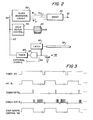
- a raster input scanner 10 incorporating the scanning control of the present invention.
- the scanning control of the present invention permits scanner 10 to respond to asynchronous demands for image signals such as may result from situations wherein the communication channel served by scanner 10 has a restricted capacity, or where scanner 10 serves a disc memory whose rate of data acceptance is less than the rate at which scanner 10 generates image signals, or to accommodate off-peak transmittal, or operator interruptions, etc. without sacrificing the quality and faithfulness of the image signals produced.
- Scanner 10 includes a platen 15 having a flat surface 16 across which documents 18 to be scanned are moved in the direction shown by the solid line arrow.
- a slit-like scanning aperture 20 is provided in the platen 15, the longitudinal axis of aperture 20 extending in the direction substantially perpendicular to the direction of movement of the document 18.
- a suitable array 24 such as a Fairchild Corporation Model 121-H linear array is provided for scanning the document image line-by-line as the document is indexed or stepped across aperture 20.
- Array 24 is disposed so that the scanning axis thereof is substantially parallel to the axis of scanning aperture 20.
- the optical path between scanning aperture 20 and array 24 includes a lens 26 for focusing the document line viewed by array 24 through aperture 20 onto the array 24.
- a reflector 31 is disposed on the other side of the optical path across from lamp 30, reflector 31 serving to reflect light emitted by lamp 30 into the aperture area. While a single array 24 is shown and described herein, it will be understood that array 24 may consist of a composite of several arrays.
- a viewing element 32 which is formed from any suitable transparent material such as glass is movably disposed within the scanning aperture 20. Viewing element 32 is mounted on a pair of leaf springs 34. Springs 34, the longitudinal axis of which extends in a direction substantially parallel to the direction of movement of the document to be scanned to reduce perturbations in the document feed, have the remote ends 34' thereof secured as by cementing to the underside of platen 15. As will be understood, leaf springs 34 bias viewing element 32 upwardly and into the confines of scanning aperture 20.
- a document transport has a document feed roll 40 rotatably mounted on support member 15 above scanning aperture 20 and the viewing element 32 therein, such that the periphery 42' of the roll 40 contacts the upper surface of viewing element 32 at a point just upstream of the optical centerline 25.
- a low friction surface 47 is preferably provided on viewing element 32 to control frictional loading on feed roll 40.
- feed roll 40 serves to step the document to be scanned along platen 15 and across the viewing element 32 one line at a time.
- feed roll 40 comprises an internal core member or shaft 41, normally metal, having a rubber sleeve 42 thereabout.
- Sleeve 42 is perferably formed from a relatively hard durometer rubber material to ensure uniform friction and provide long life.
- a step motor 45 is coupled to shaft 41 as by means of pulleys and belt (not shown), motor 45 serving to step feed roll 40 in the direction shown by the solid line arrow upon actuation thereof.
- springs 34 hold viewing element 32 in resilient contact with the periphery of feed roll 40 to form a nip between which the doucument 18 to be scanned passes.
- the bias provided by springs 34 accommodates documents of different thickness without velocity changes.
- clock pulse 0 ⁇ 1 defines the integration period during which the array photosites view the image
- clock pulse 0 ⁇ 2 the transfer period during which the charges accumulated on the array photosites are transferred to one or more on-board parallel in-serial out shift registers
- clock pulses ⁇ 3 provide the pulses to clock the image signals or pixels in serial fashion from the array shift register or registers to output.line 52.
- A- suitable step motor control 56 is provided for operating step motor 45, control 56 serving when triggered to actuate motor 45 to rotate feed roll 40 and step the document to be scanned forward for a distance of one scanline.
- a suitable sheet edge sensor 58 which may for example comprise a cooperating photocell and light disposed so that sensor 58 is actuated when the document to be scanned reaches the optical centerline 25, is provided, the output of sensor 58 being coupled through gate 57 to the control input of a suitable timer 60, and to lamp control latch 66.
- Gate 57 is enabled through lead 59 in response to a demand for image signals from the external source served by scanner 10.
- Latch 66 when set by a signal from sensor 58 in response to the presence of a document, energizes lamp 30.
- Timer 60 has the output terminal thereof coupled to the control input terminal of clock generator circuit 50 and step motor control 56 by lead 62.
- Timer 60 comprises any suitable timing mechanism such as a crystal controlled clock capable when triggered by the signal output of sensor 58 of generating a series of timed pulses in lead 62 for actuating step motor control 56 and operating scanning array 24 as will appear.
- step motor 45 On actuation of step motor 45, the document 18 is accelerated by feed roll 40 at a relatively constant rate (shown by wave segment 65") from a standing start to a maximum speed S. From this point, step motor 45 normally overshoots the position of the next scanline (i.e. the desired position) following which the inertia of the various parts, i.e. feed roll 40, step motor 45, etc., sustains a somewhat oscillatory or uneven document movement at a steadily decreasing amplitude until the document comes to a stop at the desired position. This latter document motion is illustrated by the wave portion 65' in Figure 4.
- scanning array 24 is actuated simultaneously with actuation of step motor 45 by triggering clock generator circuit 50 concurrently with step motor control 56.
- the array integration period is initiated by the clock pulse 0 ⁇ 1 from clock circuit 50 as feed roll 40 begins to advance the document 18 forward. Integration of the image line by scanning array 29 accordingly takes place during the period when the document is being accelerated by feed roll 40 at a relatively constant rate, i.e. during segment 65" of wave pattern 65.
- the image charges are transferred to the array onboard shift register or shift registers by the transfer pulse 0 ⁇ 2 and the image signals thereafter output by the clock pulses 03.
- Array charge transfer and image signal output which are independent of document movement, are accordingly carried out between acceleration impulses.
- the document 18 to be scanned is inserted into the nip formed by viewing element 32 and feed roll 40 by suitable means, for example by hand.
- sensor 58 responds to actuate timer 60 and set lamp control latch 66. Setting of latch 66 energizes lamp 30.
- timer 60 commences to generate a succession of timed control pulses in lead 62, each timed pulse serving to trigger step motor control 56 and actuate step motor 45 through one step.
- the control pulses output by timer 60 trigger clock generator circuit 50.
- Actuation of motor 45 rotates feed roll 40 through a predetermined arc to index or step the document 18 ahead one line while the clock signals 0 ⁇ 1 , 0 2 , 0 3 output by clock generator circuit 50 operate scanning array 24 in the sequence 'described to scan the image line.
- step cycle process is repeated line by line. Following scanning of the last line, movement of the document trailing edge past the optical centerline 25 resets sensor 58 to terminate operation of scanner 10.
- step scanning arrangements i.e. a scanning or moving platen; or moving lens, or mirror(s), or array, or combination thereof; etc. may be readily contemplated.
Landscapes
- Engineering & Computer Science (AREA)
- Multimedia (AREA)
- Signal Processing (AREA)
- Facsimile Scanning Arrangements (AREA)
Applications Claiming Priority (2)
| Application Number | Priority Date | Filing Date | Title |
|---|---|---|---|
| US06/316,468 US4432023A (en) | 1981-10-30 | 1981-10-30 | Raster scanner control |
| US316468 | 1981-10-30 |
Publications (3)
| Publication Number | Publication Date |
|---|---|
| EP0079183A1 true EP0079183A1 (de) | 1983-05-18 |
| EP0079183B1 EP0079183B1 (de) | 1985-12-27 |
| EP0079183B2 EP0079183B2 (de) | 1989-05-24 |
Family
ID=23229186
Family Applications (1)
| Application Number | Title | Priority Date | Filing Date |
|---|---|---|---|
| EP82305768A Expired EP0079183B2 (de) | 1981-10-30 | 1982-10-29 | Raster-Abtaster und Abtastverfahren |
Country Status (4)
| Country | Link |
|---|---|
| US (1) | US4432023A (de) |
| EP (1) | EP0079183B2 (de) |
| JP (1) | JPS5881380A (de) |
| DE (1) | DE3268186D1 (de) |
Families Citing this family (6)
| Publication number | Priority date | Publication date | Assignee | Title |
|---|---|---|---|---|
| FR2575578B1 (fr) * | 1984-12-31 | 1995-03-03 | Canon Kk | Appareil d'enregistrement et de reproduction optiques d'informations |
| JPS6370658A (ja) * | 1986-09-12 | 1988-03-30 | Canon Inc | 画像読取装置 |
| US4878119A (en) * | 1988-02-29 | 1989-10-31 | Xerox Corporation | System for synchronizing integration pulses with integration signal in an asynchronous raster input scanner |
| US5274465A (en) * | 1989-04-15 | 1993-12-28 | Samsung Electronics Co. Ltd. | Document conveying circuit for use in a facsimile system |
| US5374999A (en) * | 1992-12-22 | 1994-12-20 | Silitek Corporation | Scan control system |
| EP0975140A1 (de) * | 1998-07-21 | 2000-01-26 | Jaakov Tenné | Visitenkarten-Organizer |
Citations (3)
| Publication number | Priority date | Publication date | Assignee | Title |
|---|---|---|---|---|
| DE2840227A1 (de) * | 1977-09-15 | 1979-03-22 | Minnesota Mining & Mfg | Nichtlineare umkehrbare laengsabtaststeuerung mit mehreren geschwindigkeiten fuer faksimilemaschinen |
| DE2934559A1 (de) * | 1978-08-29 | 1980-03-06 | Ricoh Kk | Faksimile-uebertragungsverfahren und -einrichtung |
| DE2929447B2 (de) * | 1978-07-20 | 1981-06-04 | Ricoh Co., Ltd., Tokyo | Faksimile-System |
Family Cites Families (11)
| Publication number | Priority date | Publication date | Assignee | Title |
|---|---|---|---|---|
| US3637303A (en) * | 1968-06-21 | 1972-01-25 | Canon Kk | Electrophotographic copying machine having movable slit-exposure station |
| US3834805A (en) * | 1973-01-29 | 1974-09-10 | Sperry Rand Corp | Xerographic copier with asynchronous copy feed |
| US3957707A (en) * | 1974-06-21 | 1976-05-18 | The Goodyear Tire & Rubber Company | Acrylic composition and film |
| JPS5911905B2 (ja) * | 1975-12-18 | 1984-03-19 | キヤノン株式会社 | カヘンバイフクシヤキ |
| JPS52155007A (en) * | 1976-06-18 | 1977-12-23 | Matsushita Graphic Communic | Facsimile system |
| US4070089A (en) * | 1976-07-01 | 1978-01-24 | Xerox Corporation | Two dimensional laser scanner with movable cylinder lens |
| GB1566410A (en) * | 1976-12-17 | 1980-04-30 | Xerox Corp | Photocopiers |
| JPS5580954A (en) * | 1978-12-14 | 1980-06-18 | Ricoh Co Ltd | Picture information process system |
| JPS5919664B2 (ja) * | 1979-07-23 | 1984-05-08 | 日本電信電話株式会社 | フアクシミリ送信機の副走査方法 |
| JPS5626262U (de) * | 1979-08-06 | 1981-03-11 | ||
| US4367493A (en) * | 1981-04-02 | 1983-01-04 | Xerox Corporation | Raster scanner apparatus and method |
-
1981
- 1981-10-30 US US06/316,468 patent/US4432023A/en not_active Expired - Lifetime
-
1982
- 1982-10-19 JP JP57184409A patent/JPS5881380A/ja active Granted
- 1982-10-29 EP EP82305768A patent/EP0079183B2/de not_active Expired
- 1982-10-29 DE DE8282305768T patent/DE3268186D1/de not_active Expired
Patent Citations (3)
| Publication number | Priority date | Publication date | Assignee | Title |
|---|---|---|---|---|
| DE2840227A1 (de) * | 1977-09-15 | 1979-03-22 | Minnesota Mining & Mfg | Nichtlineare umkehrbare laengsabtaststeuerung mit mehreren geschwindigkeiten fuer faksimilemaschinen |
| DE2929447B2 (de) * | 1978-07-20 | 1981-06-04 | Ricoh Co., Ltd., Tokyo | Faksimile-System |
| DE2934559A1 (de) * | 1978-08-29 | 1980-03-06 | Ricoh Kk | Faksimile-uebertragungsverfahren und -einrichtung |
Also Published As
| Publication number | Publication date |
|---|---|
| JPH0531342B2 (de) | 1993-05-12 |
| EP0079183B2 (de) | 1989-05-24 |
| EP0079183B1 (de) | 1985-12-27 |
| US4432023A (en) | 1984-02-14 |
| JPS5881380A (ja) | 1983-05-16 |
| DE3268186D1 (en) | 1986-02-06 |
Similar Documents
| Publication | Publication Date | Title |
|---|---|---|
| US4748514A (en) | Variable rate scanning control | |
| US4433346A (en) | Raster input scanner | |
| US4367493A (en) | Raster scanner apparatus and method | |
| US6771397B2 (en) | Image reader for use in image forming apparatus | |
| US4878119A (en) | System for synchronizing integration pulses with integration signal in an asynchronous raster input scanner | |
| US5444555A (en) | Image reading apparatus and method for reading a document during acceleration or deceleration of a stepping motor | |
| US4432023A (en) | Raster scanner control | |
| US7102797B2 (en) | Image reading device and image forming apparatus including the image reading device | |
| JPS6233790B2 (de) | ||
| JPH07212519A (ja) | 走査装置 | |
| EP0091280A1 (de) | Abtastanordnung für Bildraster | |
| EP1793578A2 (de) | Bildauslesevorrichtung und Methode zur Bildauslesung | |
| US4380389A (en) | Document transport for raster scanners | |
| US5473445A (en) | Image scanner and image scanning method | |
| US7345796B2 (en) | Image scanner for use in image forming apparatus | |
| JPS60130966A (ja) | フアクシミリ装置の副走査方式 | |
| JPS58170169A (ja) | 画像転送制御方式 | |
| JP3162788B2 (ja) | 原稿読み取り装置 | |
| JP3571499B2 (ja) | 原稿読み取り速度制御装置 | |
| JP3066904B2 (ja) | 画像読取装置 | |
| US20050231771A1 (en) | Scanner and method thereof | |
| JPS60254870A (ja) | 画像読取装置 | |
| JPH07264358A (ja) | 読取装置 | |
| JPS60163568A (ja) | 原稿読取装置 | |
| JPH04369163A (ja) | 画像読取装置 |
Legal Events
| Date | Code | Title | Description |
|---|---|---|---|
| PUAI | Public reference made under article 153(3) epc to a published international application that has entered the european phase |
Free format text: ORIGINAL CODE: 0009012 |
|
| AK | Designated contracting states |
Designated state(s): DE FR GB |
|
| 17P | Request for examination filed |
Effective date: 19831103 |
|
| GRAA | (expected) grant |
Free format text: ORIGINAL CODE: 0009210 |
|
| AK | Designated contracting states |
Designated state(s): DE FR GB |
|
| ET | Fr: translation filed | ||
| REF | Corresponds to: |
Ref document number: 3268186 Country of ref document: DE Date of ref document: 19860206 |
|
| PLBI | Opposition filed |
Free format text: ORIGINAL CODE: 0009260 |
|
| 26 | Opposition filed |
Opponent name: OCE-NEDERLAND B.V. Effective date: 19860924 |
|
| PUAH | Patent maintained in amended form |
Free format text: ORIGINAL CODE: 0009272 |
|
| STAA | Information on the status of an ep patent application or granted ep patent |
Free format text: STATUS: PATENT MAINTAINED AS AMENDED |
|
| 27A | Patent maintained in amended form |
Effective date: 19890524 |
|
| AK | Designated contracting states |
Kind code of ref document: B2 Designated state(s): DE FR GB |
|
| ET3 | Fr: translation filed ** decision concerning opposition | ||
| PGFP | Annual fee paid to national office [announced via postgrant information from national office to epo] |
Ref country code: FR Payment date: 19991011 Year of fee payment: 18 |
|
| PGFP | Annual fee paid to national office [announced via postgrant information from national office to epo] |
Ref country code: GB Payment date: 19991027 Year of fee payment: 18 |
|
| PGFP | Annual fee paid to national office [announced via postgrant information from national office to epo] |
Ref country code: DE Payment date: 19991102 Year of fee payment: 18 |
|
| PG25 | Lapsed in a contracting state [announced via postgrant information from national office to epo] |
Ref country code: GB Free format text: LAPSE BECAUSE OF NON-PAYMENT OF DUE FEES Effective date: 20001029 |
|
| GBPC | Gb: european patent ceased through non-payment of renewal fee |
Effective date: 20001029 |
|
| PG25 | Lapsed in a contracting state [announced via postgrant information from national office to epo] |
Ref country code: FR Free format text: LAPSE BECAUSE OF NON-PAYMENT OF DUE FEES Effective date: 20010629 |
|
| PG25 | Lapsed in a contracting state [announced via postgrant information from national office to epo] |
Ref country code: DE Free format text: LAPSE BECAUSE OF NON-PAYMENT OF DUE FEES Effective date: 20010703 |
|
| REG | Reference to a national code |
Ref country code: FR Ref legal event code: ST |