EP0079012A1 - Procédé et appareil pour la fabrication de mousses thermoplastiques - Google Patents
Procédé et appareil pour la fabrication de mousses thermoplastiques Download PDFInfo
- Publication number
- EP0079012A1 EP0079012A1 EP82110028A EP82110028A EP0079012A1 EP 0079012 A1 EP0079012 A1 EP 0079012A1 EP 82110028 A EP82110028 A EP 82110028A EP 82110028 A EP82110028 A EP 82110028A EP 0079012 A1 EP0079012 A1 EP 0079012A1
- Authority
- EP
- European Patent Office
- Prior art keywords
- gas
- thermoplastic
- water
- melt
- extruder
- Prior art date
- Legal status (The legal status is an assumption and is not a legal conclusion. Google has not performed a legal analysis and makes no representation as to the accuracy of the status listed.)
- Ceased
Links
Images


Classifications
-
- B—PERFORMING OPERATIONS; TRANSPORTING
- B29—WORKING OF PLASTICS; WORKING OF SUBSTANCES IN A PLASTIC STATE IN GENERAL
- B29C—SHAPING OR JOINING OF PLASTICS; SHAPING OF MATERIAL IN A PLASTIC STATE, NOT OTHERWISE PROVIDED FOR; AFTER-TREATMENT OF THE SHAPED PRODUCTS, e.g. REPAIRING
- B29C44/00—Shaping by internal pressure generated in the material, e.g. swelling or foaming ; Producing porous or cellular expanded plastics articles
- B29C44/34—Auxiliary operations
- B29C44/3442—Mixing, kneading or conveying the foamable material
- B29C44/3446—Feeding the blowing agent
-
- B—PERFORMING OPERATIONS; TRANSPORTING
- B29—WORKING OF PLASTICS; WORKING OF SUBSTANCES IN A PLASTIC STATE IN GENERAL
- B29C—SHAPING OR JOINING OF PLASTICS; SHAPING OF MATERIAL IN A PLASTIC STATE, NOT OTHERWISE PROVIDED FOR; AFTER-TREATMENT OF THE SHAPED PRODUCTS, e.g. REPAIRING
- B29C44/00—Shaping by internal pressure generated in the material, e.g. swelling or foaming ; Producing porous or cellular expanded plastics articles
- B29C44/34—Auxiliary operations
- B29C44/3442—Mixing, kneading or conveying the foamable material
-
- B—PERFORMING OPERATIONS; TRANSPORTING
- B29—WORKING OF PLASTICS; WORKING OF SUBSTANCES IN A PLASTIC STATE IN GENERAL
- B29C—SHAPING OR JOINING OF PLASTICS; SHAPING OF MATERIAL IN A PLASTIC STATE, NOT OTHERWISE PROVIDED FOR; AFTER-TREATMENT OF THE SHAPED PRODUCTS, e.g. REPAIRING
- B29C48/00—Extrusion moulding, i.e. expressing the moulding material through a die or nozzle which imparts the desired form; Apparatus therefor
- B29C48/25—Component parts, details or accessories; Auxiliary operations
- B29C48/285—Feeding the extrusion material to the extruder
- B29C48/29—Feeding the extrusion material to the extruder in liquid form
-
- B—PERFORMING OPERATIONS; TRANSPORTING
- B29—WORKING OF PLASTICS; WORKING OF SUBSTANCES IN A PLASTIC STATE IN GENERAL
- B29C—SHAPING OR JOINING OF PLASTICS; SHAPING OF MATERIAL IN A PLASTIC STATE, NOT OTHERWISE PROVIDED FOR; AFTER-TREATMENT OF THE SHAPED PRODUCTS, e.g. REPAIRING
- B29C48/00—Extrusion moulding, i.e. expressing the moulding material through a die or nozzle which imparts the desired form; Apparatus therefor
- B29C48/25—Component parts, details or accessories; Auxiliary operations
- B29C48/285—Feeding the extrusion material to the extruder
- B29C48/295—Feeding the extrusion material to the extruder in gaseous form
-
- B—PERFORMING OPERATIONS; TRANSPORTING
- B29—WORKING OF PLASTICS; WORKING OF SUBSTANCES IN A PLASTIC STATE IN GENERAL
- B29C—SHAPING OR JOINING OF PLASTICS; SHAPING OF MATERIAL IN A PLASTIC STATE, NOT OTHERWISE PROVIDED FOR; AFTER-TREATMENT OF THE SHAPED PRODUCTS, e.g. REPAIRING
- B29C48/00—Extrusion moulding, i.e. expressing the moulding material through a die or nozzle which imparts the desired form; Apparatus therefor
- B29C48/25—Component parts, details or accessories; Auxiliary operations
- B29C48/36—Means for plasticising or homogenising the moulding material or forcing it through the nozzle or die
- B29C48/362—Means for plasticising or homogenising the moulding material or forcing it through the nozzle or die using static mixing devices
-
- B—PERFORMING OPERATIONS; TRANSPORTING
- B29—WORKING OF PLASTICS; WORKING OF SUBSTANCES IN A PLASTIC STATE IN GENERAL
- B29C—SHAPING OR JOINING OF PLASTICS; SHAPING OF MATERIAL IN A PLASTIC STATE, NOT OTHERWISE PROVIDED FOR; AFTER-TREATMENT OF THE SHAPED PRODUCTS, e.g. REPAIRING
- B29C48/00—Extrusion moulding, i.e. expressing the moulding material through a die or nozzle which imparts the desired form; Apparatus therefor
- B29C48/25—Component parts, details or accessories; Auxiliary operations
- B29C48/36—Means for plasticising or homogenising the moulding material or forcing it through the nozzle or die
- B29C48/375—Plasticisers, homogenisers or feeders comprising two or more stages
- B29C48/38—Plasticisers, homogenisers or feeders comprising two or more stages using two or more serially arranged screws in the same barrel
-
- B—PERFORMING OPERATIONS; TRANSPORTING
- B29—WORKING OF PLASTICS; WORKING OF SUBSTANCES IN A PLASTIC STATE IN GENERAL
- B29C—SHAPING OR JOINING OF PLASTICS; SHAPING OF MATERIAL IN A PLASTIC STATE, NOT OTHERWISE PROVIDED FOR; AFTER-TREATMENT OF THE SHAPED PRODUCTS, e.g. REPAIRING
- B29C48/00—Extrusion moulding, i.e. expressing the moulding material through a die or nozzle which imparts the desired form; Apparatus therefor
- B29C48/25—Component parts, details or accessories; Auxiliary operations
- B29C48/36—Means for plasticising or homogenising the moulding material or forcing it through the nozzle or die
- B29C48/50—Details of extruders
- B29C48/505—Screws
- B29C48/54—Screws with additional forward-feeding elements
-
- B—PERFORMING OPERATIONS; TRANSPORTING
- B29—WORKING OF PLASTICS; WORKING OF SUBSTANCES IN A PLASTIC STATE IN GENERAL
- B29C—SHAPING OR JOINING OF PLASTICS; SHAPING OF MATERIAL IN A PLASTIC STATE, NOT OTHERWISE PROVIDED FOR; AFTER-TREATMENT OF THE SHAPED PRODUCTS, e.g. REPAIRING
- B29C48/00—Extrusion moulding, i.e. expressing the moulding material through a die or nozzle which imparts the desired form; Apparatus therefor
- B29C48/25—Component parts, details or accessories; Auxiliary operations
- B29C48/36—Means for plasticising or homogenising the moulding material or forcing it through the nozzle or die
- B29C48/50—Details of extruders
- B29C48/505—Screws
- B29C48/585—Screws provided with gears interacting with the flow
-
- B—PERFORMING OPERATIONS; TRANSPORTING
- B29—WORKING OF PLASTICS; WORKING OF SUBSTANCES IN A PLASTIC STATE IN GENERAL
- B29C—SHAPING OR JOINING OF PLASTICS; SHAPING OF MATERIAL IN A PLASTIC STATE, NOT OTHERWISE PROVIDED FOR; AFTER-TREATMENT OF THE SHAPED PRODUCTS, e.g. REPAIRING
- B29C48/00—Extrusion moulding, i.e. expressing the moulding material through a die or nozzle which imparts the desired form; Apparatus therefor
- B29C48/25—Component parts, details or accessories; Auxiliary operations
- B29C48/36—Means for plasticising or homogenising the moulding material or forcing it through the nozzle or die
- B29C48/50—Details of extruders
- B29C48/505—Screws
- B29C48/63—Screws having sections without mixing elements or threads, i.e. having cylinder shaped sections
-
- B—PERFORMING OPERATIONS; TRANSPORTING
- B29—WORKING OF PLASTICS; WORKING OF SUBSTANCES IN A PLASTIC STATE IN GENERAL
- B29C—SHAPING OR JOINING OF PLASTICS; SHAPING OF MATERIAL IN A PLASTIC STATE, NOT OTHERWISE PROVIDED FOR; AFTER-TREATMENT OF THE SHAPED PRODUCTS, e.g. REPAIRING
- B29C48/00—Extrusion moulding, i.e. expressing the moulding material through a die or nozzle which imparts the desired form; Apparatus therefor
- B29C48/25—Component parts, details or accessories; Auxiliary operations
- B29C48/36—Means for plasticising or homogenising the moulding material or forcing it through the nozzle or die
- B29C48/50—Details of extruders
- B29C48/68—Barrels or cylinders
- B29C48/685—Barrels or cylinders characterised by their inner surfaces, e.g. having grooves, projections or threads
- B29C48/686—Barrels or cylinders characterised by their inner surfaces, e.g. having grooves, projections or threads having grooves or cavities
-
- B—PERFORMING OPERATIONS; TRANSPORTING
- B29—WORKING OF PLASTICS; WORKING OF SUBSTANCES IN A PLASTIC STATE IN GENERAL
- B29C—SHAPING OR JOINING OF PLASTICS; SHAPING OF MATERIAL IN A PLASTIC STATE, NOT OTHERWISE PROVIDED FOR; AFTER-TREATMENT OF THE SHAPED PRODUCTS, e.g. REPAIRING
- B29C48/00—Extrusion moulding, i.e. expressing the moulding material through a die or nozzle which imparts the desired form; Apparatus therefor
- B29C48/25—Component parts, details or accessories; Auxiliary operations
- B29C48/92—Measuring, controlling or regulating
-
- B—PERFORMING OPERATIONS; TRANSPORTING
- B29—WORKING OF PLASTICS; WORKING OF SUBSTANCES IN A PLASTIC STATE IN GENERAL
- B29C—SHAPING OR JOINING OF PLASTICS; SHAPING OF MATERIAL IN A PLASTIC STATE, NOT OTHERWISE PROVIDED FOR; AFTER-TREATMENT OF THE SHAPED PRODUCTS, e.g. REPAIRING
- B29C2948/00—Indexing scheme relating to extrusion moulding
- B29C2948/92—Measuring, controlling or regulating
- B29C2948/92504—Controlled parameter
- B29C2948/92676—Weight
-
- B—PERFORMING OPERATIONS; TRANSPORTING
- B29—WORKING OF PLASTICS; WORKING OF SUBSTANCES IN A PLASTIC STATE IN GENERAL
- B29C—SHAPING OR JOINING OF PLASTICS; SHAPING OF MATERIAL IN A PLASTIC STATE, NOT OTHERWISE PROVIDED FOR; AFTER-TREATMENT OF THE SHAPED PRODUCTS, e.g. REPAIRING
- B29C2948/00—Indexing scheme relating to extrusion moulding
- B29C2948/92—Measuring, controlling or regulating
- B29C2948/92819—Location or phase of control
- B29C2948/92828—Raw material handling or dosing, e.g. active hopper or feeding device
-
- B—PERFORMING OPERATIONS; TRANSPORTING
- B29—WORKING OF PLASTICS; WORKING OF SUBSTANCES IN A PLASTIC STATE IN GENERAL
- B29C—SHAPING OR JOINING OF PLASTICS; SHAPING OF MATERIAL IN A PLASTIC STATE, NOT OTHERWISE PROVIDED FOR; AFTER-TREATMENT OF THE SHAPED PRODUCTS, e.g. REPAIRING
- B29C48/00—Extrusion moulding, i.e. expressing the moulding material through a die or nozzle which imparts the desired form; Apparatus therefor
- B29C48/03—Extrusion moulding, i.e. expressing the moulding material through a die or nozzle which imparts the desired form; Apparatus therefor characterised by the shape of the extruded material at extrusion
- B29C48/07—Flat, e.g. panels
-
- B—PERFORMING OPERATIONS; TRANSPORTING
- B29—WORKING OF PLASTICS; WORKING OF SUBSTANCES IN A PLASTIC STATE IN GENERAL
- B29K—INDEXING SCHEME ASSOCIATED WITH SUBCLASSES B29B, B29C OR B29D, RELATING TO MOULDING MATERIALS OR TO MATERIALS FOR MOULDS, REINFORCEMENTS, FILLERS OR PREFORMED PARTS, e.g. INSERTS
- B29K2105/00—Condition, form or state of moulded material or of the material to be shaped
- B29K2105/0005—Condition, form or state of moulded material or of the material to be shaped containing compounding ingredients
-
- Y—GENERAL TAGGING OF NEW TECHNOLOGICAL DEVELOPMENTS; GENERAL TAGGING OF CROSS-SECTIONAL TECHNOLOGIES SPANNING OVER SEVERAL SECTIONS OF THE IPC; TECHNICAL SUBJECTS COVERED BY FORMER USPC CROSS-REFERENCE ART COLLECTIONS [XRACs] AND DIGESTS
- Y10—TECHNICAL SUBJECTS COVERED BY FORMER USPC
- Y10S—TECHNICAL SUBJECTS COVERED BY FORMER USPC CROSS-REFERENCE ART COLLECTIONS [XRACs] AND DIGESTS
- Y10S264/00—Plastic and nonmetallic article shaping or treating: processes
- Y10S264/05—Use of one or more blowing agents together
Definitions
- This invention relates to the generation of foam thermoplastic materials in the form of extrudates and more particularly, to the generation of foamed thermoplastic extrudates utilizing blowing agents other than fluorocarbons and specifically, air. nitrogen, carbon dioxide, and water either alone or in combination with themselves and othe: ingredients.
- thermoplastic foam extrudates The predominate blowing agent ior the generation of thermoplastic foam extrudates on a commercial basis has been fluorocarbons, for example, trichlorofluoromethane and dichio- tofluoromethane.
- fluorocarbons have been determined to be an undesirable pollutant ior the atmosphere. Accordingly, ways are being sought to eliminate or materially reduce the utilization of fluorocarbons for all purposes wherever possible.
- a significant area in which to eliminate fluorocarbons from manufacturing processes is in the generation of thermoplastic foam extrudates such as thermoplastic foam sheeting and the like.
- Natural gases such as air, pure nitrogen or pure carbon dioxide, all of which have predictable and acceptable effects on the ecology, would be the most desirable blowing agents.
- water since it would become vaporized in contact with molten thermoplastic masses in an extruding line or the like, is also a prime candidate for an ecologically sound blowing agent.
- Another object of the present invention is to provide a new and novel method and apparatus for injecting air, nitrogen, carbon dioxide, water, and/or combinations of these into an extrusion system configuration as blowing agents to produce foamed thermoplastic extrudate from that extr-usion system.
- Another object of the present invention is to reduce the cost of producing foamed thermoplastic extrudates.
- Still another object of the present invention is to provide foamed thermoplastic extrudates of enhanced quality.
- Yet another object of the present invention is to provide a new and novel combination of gases and/or water and/or other ingredients as the blowing and nucleating agents for the production of foamed thermoplastic extrudates and the like, thereby totally supplanting and eliminating the need for fluorocarbons in the production of such products.
- the methods of the present invention include the controlled injection of gases such as air, nitrogen and carbon dioxide and/or water and/or nucleating agents such as talc into an extrusion system upstream of the extruding di e .
- gases such as air, nitrogen and carbon dioxide and/or water and/or nucleating agents such as talc
- Some embodiments also include the addition of chemical blowing agents which further illustrate the versatility of the methods of the present invention.
- the extruder systems contemplated by the present invention are of either a single extruder or a . tandem extruder configuration with various access points at which controlled amounts of thermoplastic, nucleating agents, gas, water and/or chemical blowing agents can be added to the molten thermoplastic mass being produced by the extrusion system upstream of the extruding die.
- resin, granulates and a nucleating agent are introduced into the upstream end of an extruder and a controlled volume of water is introduced mid-way between the upstream end and the gate of the extruder valve.
- the output of the extruder then passes through a screen changer and a gear pump, in that order, through a gas injector assembly, then through a mixer (of either the static or dynamic type) and a dynamic cooler structure to an extruding die.
- the final foamed product emanates from the extruding die.
- a transducer is provided Upstream from the mixer at the gas injector assembly to maintain the proper relationship' between the speed of the pump and the pressure at the gas injection assembly to maintain a constant pressure at the point of gas injection into the system. This insures a substantially uniform flow of compressible gas into the molten extrudate upstream of the mixer and cooler assemblies to ensure a homogeneous product.
- the water injected into'the extruder barrel is accomplished by use of a metering pump or the like.
- the first extruder is provided with resin, granulates and nucleator at its upstream end, with water injection intermediate the ends of its barrel, and the output of the first extruder passes through a screen changer and a first gear pump.
- This first gear pump has its speed controlled by a transducer immediately adjacent the gas injection apparatus which is at the output of the first gear pump. Downstream and immediately adjacent the outlet end of the gas injection apparatus is a second gear pump which then feeds a mixer, the latter exhausting into the upstream end of a second extruder barrel which serves as a dynamic cooling device to bring the foamed plastic extrudate to the .
- the first and second gear pumps are provided to prevent the compressible plastic material from assuming too many variations in actual system pressure on both sides of the point of injection of gas into the molten extrudate.
- the basic design of this apparatus is an attempt to approximate molecule for molecule injection to minimize or substantially eliminate downstream mixing.
- a practical compromise is embodied in the structure of the gas injector apparatus of the present invention in-an effort to achieve optimum injection levels which when combined with a downstream mixer device will achieve substantially the same results as molecule for molecule injection.
- the gas injector assembly consists of an in-line body having a central bore with an expanded substantially cylindrical central chamber defined therein in which a flow spreader is positioned having sufficient conformality with the expanded chamber to spread the flow of incoming molten extrudate into a circular fan shape and pass it through a close tolerance annular gap between the spreader and the . walls of the chamber.
- a very small annular slot is provided in the peripheral wall of the expanded cylindrical cavity which slot is supplied with gas under pressure and causes a thin sheet of gas to be introduced into the thin sheet of thermoplastic extrudate-flowing around the flow spreader at that point.
- the flow spreader and the cavity cease to conform in a tight tolerance mode and the flow is permitted to proceed in a less impeded manner around a splined downstream portion of the flow spreader which is extended axially of the flow and which is positioned within the outlet end of the central bore of the injecting apparatus to support the flow spreader within the enlarged cylindrical bore of the injectionapparatus.
- the mixer assembly downstream of the injection apparatus is preferably of either the static or dynamic type.
- the static type is exemplified by the melt blender manufactured by the Koch Engineering Company, Inc., which melt blender is exemplified in U.S.Patents 3,785,620 and 3,871,624. This mixer is fully described and illustrated in bulletin No. KMV-2 of Koch Engineering Company, Inc., a.copy of which Bulletin is attached hereto and made a part hereof as Appendix I.
- a dynamic mixer of a preferred type basically comprises a through-bore with a series of sets of axially spaced and fixed gear shaped teeth peripherally disposed in the bore with interspersed rotary mixing gears mounted on a common shaft in the bore. Rotation of the shaft provides mixing of molten extrudate flowing in the bore by the interaction of the fixed and rotary mixing teeth.
- the dynamic cooler utilized downstream from the mixer is of the type generally exemplified in U.S. Patent 3,830,901 of Thomas W. Winstead entitled Continuous Process for Extruding Cellular Thermoplastics, issued August 20, 1974.
- Such a cooler is essentially a flow metering device which includes a cooling function such that a predetermined quantity of molten extrudate per unit time and at a preselected extrusion temperature is delivered to the extrusion die.
- Foamed thermoplastic extrudate has been produced in the systems and by the methods of the present invention utilizing water alone as a blowing agent, water and nitrogen as a combined blowing agent and water and air as a blowing agent. To these combinations have been added talc as a nucleating agent, and azodicarbonamide as a chemical blowing agent in various combinations to produce foamed extrudate which after molding in a continuous system to form molded product have ranged in density from 2.3 lbs. per cu. ft. to 21.0 lbs. per cu. ft. Various attendant cell sizes have been readily achievable which are commensurate with the densities. Both oriented and non-oriented foams have been produced utilizing the blowing agents and techniques of the invention and have been found to be highly satisfactory.
- the cell pressures achievable by the present invention are higher than the cell pressures achievable by Freon blowing agents and therefore, less brittleness is an immediate benefit achieved by the present invention in the ultimate extruded foam products.
- the oriented foams have been stretch oriented 1.5 times initial dimensions in both the machine and transverse directions of extrusion and this has been found to be highly satisfactory in producing foams of reduced brittleness and enhanced structural strength.
- water is introduced into the extruder barrel at 2000 - 3800 PSIG; gas is introduced into the injector at a delivery pressure on the order of 3200 - 5000 PSIG at 430 0 F and the extrudate is fed to the extrusion die at 260 0 - 280° F and 1300 - 3600 PSIG. All of these parameters are approximate but represent desired orders of magnitude in the process of the present invention to produce polystyrene foams of the densities referenced above.
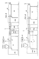
- a preferred embodiment of a single extrusion system for producing foamed thermoplastic resin is illustrated as including an extruder E having an elongated barrel B with an input hopper H positioned against the upstream end of the barrel B to receive resin Rl, granular R2 and/or nucleating material N at that point of the extruder.
- the downstream or gate end of the barrel B exhausts through a screen changer S to a controlled rate gear pump P from which controllable quantities of extrudate are emitted.
- a water injection point WI which receives water W from a controlled volume water pump WP as schematically shown.
- the controlled volume pump P is preferably a gear pump and has a variable speed drive VSD which is responsive to a control voltage from a pressured voltage to voltage transducer T, the latter being connected to the input side of a gas injection assembly I which is connected to an external source of gas or air G as will be hereinafter more fully described.
- VSD variable speed drive
- the transducer T senses the pressure at the input of the gas injector to determine whether or not there is a variation in pressure differential at that point caused by either a variation in flow of extrudate into the injector, flow of gas into the injector, or a combination of both.
- the output of the gas injector which at this point is a mixture of gas and molten extrudate is then passed through a mixer M which may be either of the static or dynamic type and thence through a dynamic cooler such as that described in U.S. Patent 3,830,901 of Thomas W. Winstead, as above identified, from whence the thoroughly mixed and cooled extrudate with entrained water and gas is delivered to the outlet die D from which it is emitted in the form of foam sheeting F.
- the water pump WP may be of a similar construction to pumps employed to inject fluorocarbons into the extruder as a blowing agent and in fact, this water injection can be acomplished at the same position on the extruder barrel B as was previously used to inject fluorocarbons therein.
- Water levels ranging from 0-8% by weight of the melt within the extruder are contemplated by the present invention. These ranges of water injection are accomplished in the 50 lb. per hour range, for example, by injection pressure ranging from 2000 to 3800 PSIG.
- the transducer T has a control link CL indicated schematically by dotted lines going back to control the speed of the drive ED of the extruder E.
- the transducer T has a control link CL indicated schematically by dotted lines going back to control the speed of the drive ED of the extruder E.
- the pressure at the intake of the gas injection apparatus I is controlled by controlling the extruder drive rather than the speed of a gear pump immediately adjacent the injection apparatus I.
- the transducer T is coupled to sense the upstream pressure entering the mixer and control the - drive ED of the extruder E to vary its speed and control the upstream pressure at the inlet of the mixer M.
- the reflection of this pressure back into the downstream gate area of the extruder barrel B tends to maintain a constant pressure differential between the flow of molten extrudate and the gas G at the injection point GI in the extruder E.
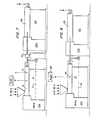
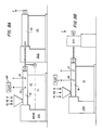
- Figures 5, 6, 7, 8, and 9 are directed to tandem extruder systems in which the upstieam extruder is designated El and the downstream extruder designated E2. Basically, the downstream extruder E2 replaces the dynamic cooler D/C of Figures 1-4. In all of the embodiments of Figures 5-9, the downstream extruder E2 feeds directly from its barrel B2 into the extruding die D to produce the desired thermoplastic foam extrudate.
- gear pumps Pl and P2 which are located immediately upstream and downstream, respectively, of the gas injection apparatus I.
- the upstream gear pump PI has its drive DSD1 controlled as to speed by the output of the transducer T in the same manner described for the embodiment of Figure 1.
- the downstream pump D2 is driven at a constant speed so that the extrudate melt which is being monitored as to pressure.is controlled both upstream and downstream of the gas injection apparatus I by positive displacement gear pumps to compensate for any compression of the extrudate melt itself and thereby reduce the compressibility effects on the stability of the system at the point of gas injection.
- a mixer either static or dynamic is illustrated as being immediately downstream from the downstream gear D2 from whence the extrudate melt with gas and water injected therein passes into the downstream extruder E2 through the barrel B2 of the latter and from that point directly to the output . die D to produce the desired foam extrudate F.
- the upstream gear pump P1 of Figure 5 has been removed and the transducer T controls the drive ED1 of the upstream extruder El through a control linkage CL indicated in dotted lines to thereby provide the pressure differential control at the point of gas injection in a manner similar to that previously described for Figure 2.
- the downstream gear pump D2 remains to isolate the gas injection point from the downstream mixer M and downstream extruder E2, thereby preventing compressibilty and instability present in the downstream extruder E2 from reflecting back to the gas injection point and the gas injection apparatus I. All of the elements of Figure 6 which are like elements to those of Figure 5 bear like designations.
- Figure 7 is similar to Figure 6 with the exception that the downstream mixer M has been removed from its position between the downstream gear pump D2 and the downstream extruder E2 and the gas ingestion point GI has been placed- adjacent the downstream gate area in the barrel Bl of the first or upstream extruder El.
- this embodiment is a manually controlled laboratory approximation of the embodiment of Figure 8A with a dynamic cooler D/C simulating the downstream extruder E2 of Figure 8A.
- the control linkage CL is approximated by manual control of the extruder drive EDI.
- the gas injec- tot assembly I is shown as having a body portion 20 comprised of an upstream half 20A and a downstream half 20B, which are coaxially bolted together by bolts 22 such that opposed surfaces 24A and 24B thereof are tightly clamped together.
- the surface 24B illustrated in plain view in Figure 11, is sandblasted to provide for the controlled leakage of gas under pressure through the junction formed by juxtaposing the said surfaces 24A and 24B.
- This gas leakage is confined to the interior most portion of the surfaces by providing an 0-Ring 26 in an 0-Ring slot 26S O-Ring 26 forms a seal about the juxtaposed surfaces 24A and 24B externally of an adjacent annular gas port 28 formed in and communicating through the downstream body portion 20B ( Figure 12) by means of a passageway 30 and an external hose connection 32 or the like to an air supply 34.
- the juxtaposed surfaces 24A and 24B are annular in configuration and join centrally located dished surfaces 36A and 36B which are co-extensive and define a centrally located mixing cavity 38 within the housing 20 between the housing section 20A and 20B.
- the upstream half of the mixing cavity 38 communicates with an inlet port 40A and a downstream half of the mixing cavity 30A communicates with an outlet port 40B, the said inlet and outlet ports being respectively connected to the upstream and downstream conduits bearing the molten thermoplastic material in the system of the present invention.
- the inlet and oulet portion 40A and 40B are coaxial and the outer extremities of the mixing chamber 38 are concentric with the common axis of the inlet and outlet ports 40A and 40B.
- the mixing chamber is circular in cross-section in a plane transverse of the axis of the inlet and outlet ports 40A and 40B and is basically rectangular with semi-circular ends in a cross-section taken along the common axis of the inlet and outlet ports 40A and 40B. This fact is clearly illustrated by Figures 10, 11 and 12.
- FIG 11, taken in conjunction with Figure 10 illustrates a flow spreader 42 in place within the mixing chamber,38.
- This flow spreader 42 is in the form of an in-line slug having a centrally located upstream spreader cone 42A which merges with a disc shaped central portion 42B in a smooth transitional configuration which in turn merges at its downstream side with a fluted flow director cone and mounting means 42C.
- the flow directing cone and mounting means 42C includes flutes 42Cl which permit the exhausting of intermixed air and/or gas and thermoplastic from the mixing chamber 38 into the outlet port 40B in the downstream half 20B of the housing of the gas injector apparatus I.
- the flow ports or flutes 42Cl are milled or otherwise formed into the cylindrical base portion 42C2 of the flow directing and mounting means 42C, the outer extremity of the said base portion being in juxtaposition with the internal wall of an enlarged portion or lead in section 40Bl of the outlet port 40B. This securely mounts the flow diverting slug 42 coaxially with both the inlet port 40A, into which the upstream diverter cone 42A extends, and the downstream or outlet port 40B.
- the disc shaped central portion 22B of the flow spreader 42 has acurately configured outer extremities 42Bl which as clearly illustrated in Figure 10 are very closely proximate to and slightly upstream from the annular line of engagement defined at the juncture of the dished surfaces 36A and 36B and their respective merger points with the sand blasted surface 24B.
- This annular junction line actually comprises an annular bleed-in or input 44 by which gas in a very thin film achieved by leakage from the gas inlet groove through the juncture 44 between the sandblasted surfaces 24B and the juxtaposed surface 24A provides a close approximation to a molecule for molecule injection of gas into a very thin film of flowing thermoplastic just downstream from the most proximate position of the flow diverter 42 and the dished surfaces of the mixing chamber 38.
- a plurality of lag screws or other stud like shims 46 are provided on the downstream face of the central portion 42B of the flow diverter 42 in mutual juxtaposition therewith and with the downstream dished surface 36B of the mixing chamber 38 to properly space the flow diverter within the said mixing chamber.
- the transducer probe for sensing the pressure at a point immediately upstream from the gas injection analysis 44 is provided by a sensing port 48 in the upstream body portion 20A of the body 20 of the injector gas injector assembly I which leads from the upstream side thereof to a point immediately adjacent the closest proximate positions of the flow diverter 42 and the dished internal surface 36A of the mixing chamber 38.
- a transducer probe assembly 50 is inserted into the sensing port with suitable connections from the probe assembly 50 back to the transducer T thereby all the variations in pressure.immediately upstream from the gas and thermoplastic mixing position in the gas injection assembly I may be monitored.
- molten extrudate is ingested through the inlet port 40A and diverted around the upstream diverter cone 42A of the flow diverter 42 from whence it is forced to flow as indicated by the flow arrows in Figure 10 through an annular gap created by the symmetrical proximity of the outer most periphery 42B1 of the flow diverter 42 and the conformally shaped internal upstream surface 36A to present a thin annular.film of molten thermoplastic to the annular gas injection junction 44 which provides, likewise, a very thin sheet of gas to be intermixed with the very thin sheet of molten thermoplastic to provide an approximation of molecule for molecule intermix of these two materials and thence, the admixed thermoplastic and entrained gas proceeds around the shims or studs 46 and through the flutes 42Cl over the downstream flow directing cone 42C and out through the outlet port 40B to be further processed by the systems of the present invention downstream.
- a dynamic mixer DM of the present invention is shown as including a body portion 60 having a through-bore 62 and a right angle bore 64 communicating therewith at the upstream most end of the body portion 60 such that the right angle bore 64 comprises an inlet port into which thermoplastic melt received from the gas injection apparatus I is ingested.
- a dynamic mixer shait assembly 66 which is sealed adjacent the right angle bore 64 by means of an 0-ring seal 68 or the like to prevent leakage of ingested melt from the upstream end of the through-bore 62.
- a dotted line connecting link 70 is also schematically indicated at the driving interconnection between the power source 68 and the drive hub 66A.
- the dynamic mixer shaft 66 is provided with an auger feed section 66B positioned in the intersection or junction of the right angles 64 and the through-bore 62 such that molten extrudate received from the right angle bore 64 will be forced downstream in through-bore 62 by the auger section 66B upon rotation of the dynamic mixer shaft 66.
- the flow of molten thermoplastic material is illustrated by suitable flow arrows in the right angle port 64 and through port 62.
- a like number of basically complimentary fixed and spaced gear piece configuration 70 disposed peripherally about the inner extremities of the through-bore 62 in a coextensive array with the geared toothed section 66B of the mixe shaft 66 are provided as shown in a side section in Figure 13 and in plan in Figure 16 to interact with and be interspersed between each pair of adjacent gear structures 66Dl on the toothed section 66D of the mixer shaft 66.
- Rotation of the mixer shaft 66 causes the rotary teeth to churn and to homogenize the molten thermoplastic by interaction with the fixed gear piece 70 surrounding the inner periphery of the through-bore 62 such that discharged thermoplastic melt from the downstream end 62A of the through-bore 62 has been further homogenized by the action of the dynamic mixer DM.
- This mixer also further homogenizes the intermix gas and molten thermoplastic received from the gas injection assembly by as well as assuring uniformity of mix of other ingredients in the thermoplastic melt prior to delivery thereof to the downstream extrusion die D.
- Polystyrene resin of a high molecular weight, high heat type such as Foster Grant's high-heat type 58DG is fed through an extruder system in the configuration of Figure 1, such that a thermoplastic melt is provided at the extruder gate at a temperature on the order of 398°F.
- the pressure of the melt upstream of the extruder gate is 5500 PSIG and downstream is 5000 PSIG at a through-put of 44 lbs./hr. Water is injected into the extruder barrel and the melt by a constant displacement pump operating in a pressure range of 3100 to 3500 PSIG.
- a mixing action is imparted to the melt with entrained water downstream from the extruder at a temperature of 400 F after which the melt is delivered through a controlled cooler to an extrusion die at 3500 PSIG and a temperature of 278°F to form an extruded sheet of foamed thermoplastic material having a thickness of the order of 0.160 inches and density of 12.7 lbs./cubic foot.
- Example A The resin of Example A with the addition of 4% talc by weight as a nucleant was run through an extruder system in the configuration of Figure 1 and water injected by constant displacement pump at pressures in the range of 2900 to 3300 PSIG. A mixing action was imparted at 380°F and controlled cooling effected to deliver the thermoplastic melt with entrained nucleant and water to an extrusion die at 3600 PSIG and a temperature of 283°F.
- the resultant extruder foamed thermoplastic sheet product of 0.190 inches thickness and a density of 8.9 lbs./cubic foot was left in flat sheets as well as thermoformed while still hot into the shape of meat trays.
- examples 11 and 12 deal with injection of gas directly into the extruder barrel at a given ga. pressure and with no downstream mixer.
- the injection pressure, injection temperature and mixer RPM are not applicable (N/A) as indicated.
Landscapes
- Engineering & Computer Science (AREA)
- Mechanical Engineering (AREA)
- Extrusion Moulding Of Plastics Or The Like (AREA)
- Manufacture Of Porous Articles, And Recovery And Treatment Of Waste Products (AREA)
- Molding Of Porous Articles (AREA)
Applications Claiming Priority (2)
| Application Number | Priority Date | Filing Date | Title |
|---|---|---|---|
| US06/319,403 US4436679A (en) | 1981-11-09 | 1981-11-09 | Method and apparatus for generating foamed thermoplastic materials |
| US319403 | 1994-10-06 |
Publications (1)
| Publication Number | Publication Date |
|---|---|
| EP0079012A1 true EP0079012A1 (fr) | 1983-05-18 |
Family
ID=23242115
Family Applications (1)
| Application Number | Title | Priority Date | Filing Date |
|---|---|---|---|
| EP82110028A Ceased EP0079012A1 (fr) | 1981-11-09 | 1982-10-29 | Procédé et appareil pour la fabrication de mousses thermoplastiques |
Country Status (6)
| Country | Link |
|---|---|
| US (1) | US4436679A (fr) |
| EP (1) | EP0079012A1 (fr) |
| JP (1) | JPS58126127A (fr) |
| AU (1) | AU554046B2 (fr) |
| BR (1) | BR8206396A (fr) |
| CA (1) | CA1189266A (fr) |
Cited By (11)
| Publication number | Priority date | Publication date | Assignee | Title |
|---|---|---|---|---|
| EP0291179A1 (fr) * | 1987-04-15 | 1988-11-17 | The Dow Chemical Company | Préparation de mousses en polymère alkénylique aromatique et produits obtenus |
| EP0329810A1 (fr) * | 1988-02-25 | 1989-08-30 | Idemitsu Petrochemical Co. Ltd. | Procédé de fabrication de feuilles en résine thermoplastique et installation à cet effet |
| EP0376671A2 (fr) * | 1988-12-27 | 1990-07-04 | The Dow Chemical Company | Procédé et dispositif pour fabriquer des mousses thermoplastiques |
| EP0445847A2 (fr) * | 1987-04-15 | 1991-09-11 | The Dow Chemical Company | Préparation de mousses en polymère et produits obtenus |
| EP0463759A2 (fr) * | 1990-06-20 | 1992-01-02 | Rapra Technology Limited | Procédé de production de mousse thermoplastique |
| EP0486957A1 (fr) * | 1990-11-20 | 1992-05-27 | Linde Aktiengesellschaft | Procédé d'utilisation d'un gaz inerte pour la production de mousse plastique |
| EP0668139A1 (fr) * | 1994-02-21 | 1995-08-23 | Sulzer Chemtech AG | Procédé pour la préparation de granules plastiques expansibles |
| EP0887167A1 (fr) * | 1994-10-11 | 1998-12-30 | The Dow Chemical Company | Mousse obtenue par injection d'eau en aval |
| US6136396A (en) * | 1996-08-12 | 2000-10-24 | Tenneco Packaging Inc. | Polymeric articles having antistatic properties and methods for their manufacture |
| EP2138294A1 (fr) | 2008-06-25 | 2009-12-30 | Sulzer Chemtech AG | Procédé et dispositif destinés à introduire un moyen d'entraînement |
| EP3831573A4 (fr) * | 2018-12-26 | 2021-11-03 | Toray Industries, Inc. | Procédé de fabrication de feuille, procédé de fabrication de film microporeux de polyoléfine, dispositif de mesure de malaxage et dispositif d'évacuation |
Families Citing this family (42)
| Publication number | Priority date | Publication date | Assignee | Title |
|---|---|---|---|---|
| JPS6089318A (ja) * | 1983-10-24 | 1985-05-20 | Toshiba Mach Co Ltd | 射出成形方法 |
| US4486550A (en) * | 1984-04-24 | 1984-12-04 | The Dow Chemical Company | Styrenic foam and process therefor |
| US4746478A (en) * | 1985-07-24 | 1988-05-24 | Sekisui Kaseihin Kogyo Kabushiki Kaisha | Method and apparatus for production of foamed thermoplastic material |
| CA1255866A (fr) * | 1985-07-24 | 1989-06-20 | Hiromu Fujisaki | Methode et diapositif de production d'un materiau thermoplastique mousse |
| DE3615586C1 (de) * | 1986-05-09 | 1987-05-07 | Berstorff Gmbh Masch Hermann | Strangpressvorrichtung zum Herstellen von Kunststoffschmelzemischungen |
| US4790207A (en) * | 1986-11-14 | 1988-12-13 | Huffy Corporation | Bicycle control lever mounting system |
| JPH0641161B2 (ja) * | 1988-02-17 | 1994-06-01 | 積水化成品工業株式会社 | スチレン系樹脂発泡シートの製造方法及び加熱成形用スチレン系樹脂発泡シート |
| US5055272A (en) * | 1989-01-13 | 1991-10-08 | Sealed Air Corporation | Method for producing polyurethane foam and apparatus therefor |
| US5118720A (en) * | 1989-01-13 | 1992-06-02 | Sealed Air Corporation | Method for producing polyurethane foam and apparatus therefor |
| US5082608A (en) * | 1990-06-14 | 1992-01-21 | Owens-Illinois Plastic Products Inc. | Polystyrene foam sheet manufacture |
| US5423607A (en) * | 1991-05-03 | 1995-06-13 | Dolco Packaging Corp. | Method for blending diverse blowing agents |
| US5340844A (en) * | 1992-04-24 | 1994-08-23 | The Dow Chemical Company | Polystyrene foam and a process for making the same |
| US5322664A (en) * | 1993-02-02 | 1994-06-21 | Owens-Illinois Labels Inc. | Clear film extrusion from an annular die |
| US5514192A (en) * | 1993-02-09 | 1996-05-07 | Grigsby, Jr.; Jerry L. | Plastic stonewashing stone and method |
| US5411683B1 (en) * | 1993-08-20 | 2000-08-01 | Sweetheart Cup Co | Method for making thermoplastic foam with combined 1,1-difluoroethane and co2 blowing agent |
| US5753717A (en) * | 1994-03-30 | 1998-05-19 | Aci Operations Pty Ltd. | Plastics foam and method of manufacturing same |
| WO1996025281A1 (fr) * | 1995-02-14 | 1996-08-22 | Robert Michael Branger | Preparation de mousses polymeres |
| WO1997006935A1 (fr) * | 1995-08-14 | 1997-02-27 | Massachusetts Institute Of Technology | Dispositif d'etranglement a engrenage en tant que dispositif de nuceation dans un systeme d'extrusion en continu d'un materiau microcellulaire |
| US6113374A (en) * | 1996-08-14 | 2000-09-05 | Owens Corning Fiberglass Technology, Inc. | Foam extrusion apparatus |
| US6884377B1 (en) | 1996-08-27 | 2005-04-26 | Trexel, Inc. | Method and apparatus for microcellular polymer extrusion |
| ATE295254T1 (de) | 1996-08-27 | 2005-05-15 | Trexel Inc | Verfahren zum extrudieren von mikrozellenpolymeren |
| US5889069A (en) * | 1997-07-15 | 1999-03-30 | The Dow Chemical Company | High temperature syndiotactic styrene polymer foam |
| US5900199A (en) * | 1997-11-21 | 1999-05-04 | Algonquin Automotive | Process for making a vehicle grille guard |
| US6103154A (en) * | 1998-02-27 | 2000-08-15 | Reebok International Ltd. | Method of molding cross-linked foamed compositions |
| US6206558B1 (en) | 1998-03-27 | 2001-03-27 | Sencorp Systems, Inc. | Extrusion system |
| PT1022303E (pt) * | 1999-01-20 | 2001-10-30 | Poliglas Sa | Processo e aparelho para produzir espuma de polistireno e blocos e placas produzidos com a referida espuma |
| US6391931B1 (en) | 1999-04-28 | 2002-05-21 | 3M Innovative Properties Co | Uniform small cell foams and a continuous process for making same |
| GB2354965A (en) * | 1999-07-20 | 2001-04-11 | Gas Injection Ltd | Extrusion sizing/calibration dies with gas pressure control |
| US8557884B2 (en) * | 2002-05-31 | 2013-10-15 | Owens Corning Intellectual Capital, Llc | To enhance the thermal insulation of polymeric foam by reducing cell anisotropic ratio and the method for production thereof |
| US8733405B2 (en) | 2005-03-14 | 2014-05-27 | Advanced Drainage Systems, Inc. | Corrugated pipe with outer layer |
| ITMO20050135A1 (it) * | 2005-06-03 | 2006-12-04 | Coopbox Europ S P A | Procedimento per la produzione di polistirolo espanso. |
| CA2622695C (fr) * | 2007-02-26 | 2015-11-03 | Advanced Drainage Systems, Inc. | Appareil et methode de voie d'acheminement de filiere d'extrusion pour tubes |
| CA2622692C (fr) * | 2007-02-26 | 2015-10-06 | Advanced Drainage Systems, Inc. | Matrice de tuyau double paroi a rapport defini |
| US20080290538A1 (en) * | 2007-05-23 | 2008-11-27 | Biesenberger Jeffrey J | Extruder ramp-up control system and method |
| US8820800B2 (en) * | 2007-11-16 | 2014-09-02 | Advanced Drainage Systems, Inc. | Multi-wall corrugated pipe couplings and methods |
| US8820801B2 (en) * | 2007-11-16 | 2014-09-02 | Advanced Drainage System, Inc. | Multi-wall corrugated pipe couplings and methods |
| US8114324B2 (en) | 2008-10-14 | 2012-02-14 | Advanced Drainage Systems, Inc. | Apparatus and method for pressing an outer wall of pipe |
| US7988438B2 (en) * | 2008-02-11 | 2011-08-02 | Advanced Drainage Systems, Inc. | Extrusion die vacuum seals |
| US20100089074A1 (en) * | 2008-10-14 | 2010-04-15 | Sutton Gerald S | Apparatus and Method for Cooling an Outer Wall of Pipe |
| US8550807B2 (en) * | 2008-05-28 | 2013-10-08 | Advanced Drainage Systems, Inc. | In-mold punch apparatus and methods |
| JP2015500155A (ja) | 2011-12-15 | 2015-01-05 | スティロン ヨーロッパ ゲゼルシャフト ミット ベシュレンクテル ハフツング | 動的混合ポンプ |
| WO2018027006A1 (fr) | 2016-08-03 | 2018-02-08 | Corning Incorporated | Appareil et procédés de régulation de rhéologie de lots de précurseurs de céramique |
Citations (6)
| Publication number | Priority date | Publication date | Assignee | Title |
|---|---|---|---|---|
| AT241099B (de) * | 1959-07-22 | 1965-07-12 | Foster Grant Co Inc | Verfahren zur Herstellung eines Körpers aus schaumfähigen thermoplastischen Kunststoffen und danach hergestellter Schaumstoffkörper |
| US3439622A (en) * | 1966-09-02 | 1969-04-22 | Phillips Petroleum Co | Motor control circuit utilizing a voltage controlled rectifier |
| DE1704824A1 (de) * | 1966-04-13 | 1971-05-19 | Mobil Oil Corp | Verfahren und Vorrichtung zum Erzeugen bzw.Ausstossen thermoplastischen Schaummaterials |
| US3830901A (en) * | 1968-09-09 | 1974-08-20 | T Winstead | Continuous process for extruding cellular thermoplastics |
| DE2544559A1 (de) * | 1975-10-04 | 1977-04-07 | Bayer Ag | Verfahren und vorrichtung zum herstellen eines reaktionsgemisches fuer die produktion von schaumstoff |
| DE2501966B2 (de) * | 1974-01-22 | 1978-10-12 | The Furukawa Electric Co. Ltd., Tokio | Einrichtung zum Strangpressen von Schaumstoff artikeln |
Family Cites Families (11)
| Publication number | Priority date | Publication date | Assignee | Title |
|---|---|---|---|---|
| DE1704824U (de) | 1955-06-02 | 1955-08-18 | Ernst Jacobi Fa | Vorrichtung zur fadenabsaugung an spinnmaschinen. |
| US3089857A (en) | 1960-04-12 | 1963-05-14 | Koppers Co Inc | Storage stable expandable polymeric composition containing expandable polymeric particles and two different blowing agents and method of making same |
| US3711067A (en) | 1971-01-08 | 1973-01-16 | Midland Ross Corp | Extruding and mixing equipment |
| CH537208A (de) | 1971-04-29 | 1973-07-13 | Sulzer Ag | Mischeinrichtung für fliessfähige Medien |
| US3792839A (en) | 1971-08-23 | 1974-02-19 | Polysar Ltd | Device for the injection of fluid foaming agents into plasticized polymeric material |
| US3796779A (en) | 1972-02-02 | 1974-03-12 | Bischoff Chemical Corp | Mixing of molten plastic and gas |
| US3940467A (en) | 1973-07-20 | 1976-02-24 | Bethlehem Steel Corporation | Method of injection molding a structural foamed thermoplastic article having a uniform swirl-free and indent-free surface |
| DE2440022C2 (de) | 1974-08-21 | 1982-07-08 | Bayer Ag, 5090 Leverkusen | Verfahren zur Herstellung von Dämm- und Leichtbaustoffen und Vorrichtung zur Durchführung dieses Verfahrens |
| US4302409A (en) | 1975-09-04 | 1981-11-24 | Union Carbide Corporation | Method for the extrusion of thermoplastic material composites |
| DE2713181A1 (de) | 1977-03-25 | 1978-10-05 | Kabel Metallwerke Ghh | Verfahren zur herstellung geschaeumter materialien |
| US4211523A (en) | 1978-11-29 | 1980-07-08 | Hoover Universal, Inc. | Gas-flow control apparatus for equipment for producing foamed plastic |
-
1981
- 1981-11-09 US US06/319,403 patent/US4436679A/en not_active Expired - Lifetime
-
1982
- 1982-10-29 EP EP82110028A patent/EP0079012A1/fr not_active Ceased
- 1982-11-02 CA CA000414685A patent/CA1189266A/fr not_active Expired
- 1982-11-03 AU AU90138/82A patent/AU554046B2/en not_active Ceased
- 1982-11-04 BR BR8206396A patent/BR8206396A/pt unknown
- 1982-11-08 JP JP57196704A patent/JPS58126127A/ja active Pending
Patent Citations (6)
| Publication number | Priority date | Publication date | Assignee | Title |
|---|---|---|---|---|
| AT241099B (de) * | 1959-07-22 | 1965-07-12 | Foster Grant Co Inc | Verfahren zur Herstellung eines Körpers aus schaumfähigen thermoplastischen Kunststoffen und danach hergestellter Schaumstoffkörper |
| DE1704824A1 (de) * | 1966-04-13 | 1971-05-19 | Mobil Oil Corp | Verfahren und Vorrichtung zum Erzeugen bzw.Ausstossen thermoplastischen Schaummaterials |
| US3439622A (en) * | 1966-09-02 | 1969-04-22 | Phillips Petroleum Co | Motor control circuit utilizing a voltage controlled rectifier |
| US3830901A (en) * | 1968-09-09 | 1974-08-20 | T Winstead | Continuous process for extruding cellular thermoplastics |
| DE2501966B2 (de) * | 1974-01-22 | 1978-10-12 | The Furukawa Electric Co. Ltd., Tokio | Einrichtung zum Strangpressen von Schaumstoff artikeln |
| DE2544559A1 (de) * | 1975-10-04 | 1977-04-07 | Bayer Ag | Verfahren und vorrichtung zum herstellen eines reaktionsgemisches fuer die produktion von schaumstoff |
Non-Patent Citations (1)
| Title |
|---|
| REGELUNGSTECHNISCHE PRAXIS, vol. 17, Heft 9, 1975, Munich W. ALLERDISSE "Messen, Regeln und Steuern an Spritzgiessmaschinen" pages 266-273 page 268, left column, line 3 page 269, left column, line 3 fig. 1, 2 * |
Cited By (16)
| Publication number | Priority date | Publication date | Assignee | Title |
|---|---|---|---|---|
| EP0445847A2 (fr) * | 1987-04-15 | 1991-09-11 | The Dow Chemical Company | Préparation de mousses en polymère et produits obtenus |
| EP0445847A3 (en) * | 1987-04-15 | 1992-01-15 | The Dow Chemical Company | Preparation of polymer foam and product |
| EP0291179A1 (fr) * | 1987-04-15 | 1988-11-17 | The Dow Chemical Company | Préparation de mousses en polymère alkénylique aromatique et produits obtenus |
| EP0329810A1 (fr) * | 1988-02-25 | 1989-08-30 | Idemitsu Petrochemical Co. Ltd. | Procédé de fabrication de feuilles en résine thermoplastique et installation à cet effet |
| US4863653A (en) * | 1988-02-25 | 1989-09-05 | Idemitsu Petrochemical Co., Ltd. | Process of producing thermoplastic resin sheet and equipment therefor |
| EP0376671A2 (fr) * | 1988-12-27 | 1990-07-04 | The Dow Chemical Company | Procédé et dispositif pour fabriquer des mousses thermoplastiques |
| EP0376671A3 (fr) * | 1988-12-27 | 1992-04-15 | The Dow Chemical Company | Procédé et dispositif pour fabriquer des mousses thermoplastiques |
| EP0463759A3 (en) * | 1990-06-20 | 1992-07-22 | Rapra Technology Limited | Production of thermoplastics foams |
| EP0463759A2 (fr) * | 1990-06-20 | 1992-01-02 | Rapra Technology Limited | Procédé de production de mousse thermoplastique |
| EP0486957A1 (fr) * | 1990-11-20 | 1992-05-27 | Linde Aktiengesellschaft | Procédé d'utilisation d'un gaz inerte pour la production de mousse plastique |
| EP0668139A1 (fr) * | 1994-02-21 | 1995-08-23 | Sulzer Chemtech AG | Procédé pour la préparation de granules plastiques expansibles |
| EP0887167A1 (fr) * | 1994-10-11 | 1998-12-30 | The Dow Chemical Company | Mousse obtenue par injection d'eau en aval |
| US6136396A (en) * | 1996-08-12 | 2000-10-24 | Tenneco Packaging Inc. | Polymeric articles having antistatic properties and methods for their manufacture |
| EP2138294A1 (fr) | 2008-06-25 | 2009-12-30 | Sulzer Chemtech AG | Procédé et dispositif destinés à introduire un moyen d'entraînement |
| US8246237B2 (en) | 2008-06-25 | 2012-08-21 | Sulzer Chemtech Ag | Apparatus and method for the introduction of a foaming agent into a polymer melt |
| EP3831573A4 (fr) * | 2018-12-26 | 2021-11-03 | Toray Industries, Inc. | Procédé de fabrication de feuille, procédé de fabrication de film microporeux de polyoléfine, dispositif de mesure de malaxage et dispositif d'évacuation |
Also Published As
| Publication number | Publication date |
|---|---|
| US4436679A (en) | 1984-03-13 |
| AU554046B2 (en) | 1986-08-07 |
| CA1189266A (fr) | 1985-06-25 |
| BR8206396A (pt) | 1983-09-27 |
| JPS58126127A (ja) | 1983-07-27 |
| AU9013882A (en) | 1983-05-19 |
Similar Documents
| Publication | Publication Date | Title |
|---|---|---|
| US4436679A (en) | Method and apparatus for generating foamed thermoplastic materials | |
| US3792839A (en) | Device for the injection of fluid foaming agents into plasticized polymeric material | |
| CN109228003B (zh) | 一种利用超临界混合流体挤出发泡制备低密度聚合物泡沫珠粒的装置及方法 | |
| US4124307A (en) | Homogenizer for viscous materials | |
| EP0463759A2 (fr) | Procédé de production de mousse thermoplastique | |
| US3146493A (en) | Process and apparatus for the production of polyolefine granulates | |
| KR920011681A (ko) | 고성능 압출기 | |
| CN1017587B (zh) | 挤出食品的方法和设备 | |
| KR960703061A (ko) | 폴리머 폼을 제조하기 위해 액체 물질에 있는 소형 버블을 분산하기 위한 장치 및 방법(Apparatus and method for the dispersion of minute bubbles in liquid materials for the production of polymer foams) | |
| US3930782A (en) | Apparatus for extruding plastic material | |
| GB917731A (en) | Method of and apparatus for pumping and/or extruding visco-elastic materials | |
| US4082488A (en) | Apparatus for the extrusion of temperature sensitive thermoplastics | |
| AU650268B2 (en) | A dynamic mixing system and method for producing thermoplastic materials | |
| US6676395B2 (en) | Equipment for extruding an expanded polymer sheet or plate | |
| FI980800A (fi) | Menetelmä ja laitteisto muovikalvon valmistamiseksi ja muovikalvo | |
| US3499186A (en) | Extruder for producing porous shaped resinous articles | |
| US3316335A (en) | Method and apparatus for continuously extruding and foaming plastics | |
| CN110901013A (zh) | 一种多功能螺杆挤出机 | |
| US3609807A (en) | Rotary plate extruding machine | |
| US3302934A (en) | Apparatus for making porous materials | |
| AU1428388A (en) | Apparatus and method for producing foamed materials | |
| JPS5670923A (en) | Method of and apparatus for producing thermoplastic resin foamed body | |
| JPS644225A (en) | Material mixing method and mixer | |
| CN221022223U (zh) | 基于熔体自密封的超临界流体辅助聚合物挤出发泡装置 | |
| CN109228004B (zh) | 基于聚四氟乙烯和滑石粉耦合改性的挤出发泡制备低密度peba珠粒泡沫的方法 |
Legal Events
| Date | Code | Title | Description |
|---|---|---|---|
| PUAI | Public reference made under article 153(3) epc to a published international application that has entered the european phase |
Free format text: ORIGINAL CODE: 0009012 |
|
| AK | Designated contracting states |
Designated state(s): AT BE CH DE FR GB IT LI LU NL SE |
|
| 17P | Request for examination filed |
Effective date: 19830419 |
|
| STAA | Information on the status of an ep patent application or granted ep patent |
Free format text: STATUS: THE APPLICATION HAS BEEN REFUSED |
|
| 18R | Application refused |
Effective date: 19860420 |
|
| RIN1 | Information on inventor provided before grant (corrected) |
Inventor name: WINSTEAD, THOMAS W. |