EP0078751B1 - Dispositif de détection de dégonflement d'un pneumatique de guidage - Google Patents
Dispositif de détection de dégonflement d'un pneumatique de guidage Download PDFInfo
- Publication number
- EP0078751B1 EP0078751B1 EP82402032A EP82402032A EP0078751B1 EP 0078751 B1 EP0078751 B1 EP 0078751B1 EP 82402032 A EP82402032 A EP 82402032A EP 82402032 A EP82402032 A EP 82402032A EP 0078751 B1 EP0078751 B1 EP 0078751B1
- Authority
- EP
- European Patent Office
- Prior art keywords
- roadway
- sensors
- sensing means
- deflation
- guide
- Prior art date
- Legal status (The legal status is an assumption and is not a legal conclusion. Google has not performed a legal analysis and makes no representation as to the accuracy of the status listed.)
- Expired
Links
- 238000001514 detection method Methods 0.000 claims description 12
- 230000008719 thickening Effects 0.000 claims description 7
- 239000002184 metal Substances 0.000 claims description 5
- 230000007246 mechanism Effects 0.000 claims 1
- 238000006073 displacement reaction Methods 0.000 description 18
- 238000005259 measurement Methods 0.000 description 2
- 238000005452 bending Methods 0.000 description 1
- 230000005540 biological transmission Effects 0.000 description 1
- 238000010586 diagram Methods 0.000 description 1
- 238000003754 machining Methods 0.000 description 1
- 230000002035 prolonged effect Effects 0.000 description 1
- 230000003313 weakening effect Effects 0.000 description 1
Images
Classifications
-
- G—PHYSICS
- G01—MEASURING; TESTING
- G01L—MEASURING FORCE, STRESS, TORQUE, WORK, MECHANICAL POWER, MECHANICAL EFFICIENCY, OR FLUID PRESSURE
- G01L17/00—Devices or apparatus for measuring tyre pressure or the pressure in other inflated bodies
- G01L17/005—Devices or apparatus for measuring tyre pressure or the pressure in other inflated bodies using a sensor contacting the exterior surface, e.g. for measuring deformation
-
- B—PERFORMING OPERATIONS; TRANSPORTING
- B61—RAILWAYS
- B61F—RAIL VEHICLE SUSPENSIONS, e.g. UNDERFRAMES, BOGIES OR ARRANGEMENTS OF WHEEL AXLES; RAIL VEHICLES FOR USE ON TRACKS OF DIFFERENT WIDTH; PREVENTING DERAILING OF RAIL VEHICLES; WHEEL GUARDS, OBSTRUCTION REMOVERS OR THE LIKE FOR RAIL VEHICLES
- B61F13/00—Rail vehicles characterised by wheel arrangements, not otherwise provided for
Definitions
- the present invention relates to a device for detecting the deflation of one of the guide tires of a vehicle on track, these tires being carried, symmetrically with respect to the axis of fixed guide means belonging to the track, by a support structure connected to the vehicle chassis.
- the invention finds a particularly important application in guided vehicles using horizontal pneumatic guide wheels rigidly connected to the axles and based either on two guide bars placed symmetrically with respect to the axis of the track, or on a single bar of guidance they enclose: such vehicles are for example used in the VAL system in Lille (France).
- Another known device provided for detecting only the deflation of lift tires (GB-A-2 019 073) comprises, for each wheel or each pair of twin wheels, a rigid disc integral with the wheel. This disc closes a switch if the tire sags.
- the present invention aims to provide a detection device which meets the requirements of practice better than those previously known, in particular in that it is of low cost and of sufficient reliability.
- the invention provides a device which includes means for detecting the displacement of the support structure relative to its nominal position.
- the approach to the problem used by the invention is completely different from those previously adopted in the sense that no component of the device is on board vehicles and that the device, therefore located on the ground, has no movable or flexible element. .
- the devices are based on the observation that the probability of simultaneous and symmetrical deflation of the two opposite guide wheels is extremely low.
- the detection means will be carried by the track and placed so as to detect the displacement of the support structure with respect to a component of the track, for example with respect to the guide means themselves.
- the guide means are provided to impose on the tires an increased load at these locations. This increased load can be caused by a tightening of the guide bars in the detection zone if these guide means comprise two bars, by a thickening of the single bar if the guide means comprise a single bar clamped by the tires.
- the left and right guide wheels are inflated in a substantially identical manner, there is no significant displacement of the support structure of the guide wheels when passing through the tightening or thickening zone. If, on the other hand, a tire is deflated, the stiffnesses of the tires differ and the support structure moves until the horizontal forces applied to each of the guide wheels are balanced.
- the displacement of the support structure will obviously depend on the extent of the tightening or thickening.
- This tightening or thickening is necessary because, in the current track, the displacement will generally be too small to be able to be distinguished from those resulting from normal deflections in laces due to various causes. These causes include track irregularities, braking forces, wind action, centrifugal force in curves. The travel will be chosen so that it does not induce excessive forces on the guide wheels and their support structure during normal operation. In practice, the tightening or thickening will be chosen so that the forces it causes do not exceed those encountered in the curves of the track in normal operation. On the other hand, this tightening or this thickening will be chosen to cause a significant displacement, typically of the order of a centimeter, in the event of deflation of a wheel.
- the displacement measurement will advantageously be carried out on a point of the support structure or of the members which are linked to it which is close to the running plane. If the support structure is free in yaw, this measurement will be made at a point distant from the yaw axis.
- the detection means will generally consist at least of a contactless displacement sensor, possibly associated with a circuit which provides an alarm signal only when the signal supplied by the sensor exceeds a threshold corresponding to a displacement of the order of a centimeter. Since the part whose travel is detected is generally metallic, electromagnetic proximity sensors of the conventional type will generally be used.
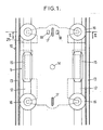
- the detection device equips a track 10 comprising two support rails 12 and two guide bars 13.
- the vehicle traveling on the track (not shown) is equipped with simple axles.
- the axle 11 shown in part in Figures 1 and 2 is provided with a pivot 14 ( Figure 1) rotating on the chassis of the vehicle.
- This axle is provided with two supporting wheels 15 which rest on the rails 12.
- It has a support structure shown schematically at 15 (FIG. 1) in the form of a plate, the four angles of which are provided with horizontal guide wheels 16 equipped with tires which bear on the bars 13.
- the wheels 16 guide the running part of the track.
- the guide means are completed by two rollers 17, connected to the structure by rigid means not shown, intended for guiding the vehicle in the track apparatus and in particular in the switches.
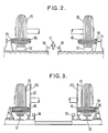
- the detection means which make it possible to detect the transverse displacements of the rollers 17 caused by a deflation, comprise, at locations distributed along the track, proximity sensors 18. These sensors will generally be of the electromagnetic type, the rollers 17 being metallic. To increase the amplitude of the displacement caused by a deflation, the bearing surfaces of the ramps 13 are brought together in the areas where the sensors are placed 18. This approximation can be achieved by placing sections locally on ramps of constant section. flat metal 19 of appropriate thickness or by bending the guide bars.
- the sensors 18 are associated with electronics not shown, providing an alarm signal when the approach exceeds a determined threshold which results in a preselected amplitude of the signal supplied by a sensor or a predetermined difference between the signals supplied by the two sensors.
- the following characteristics of a device intended for a metropolitan network can be given, by way of example.
- the two sensors 18, of electromagnetic type are placed opposite the guide rollers 17, 28 mm from these rollers. Their range is 25 mm.
- the guide ramps 13 have an additional thickness of 2x10 mm at the level of the sensors, which reduces the spacing between ramps from 2130 to 2110 mm. When all the guide tires are at nominal pressure, there is no detection signal.
- FIG. 3 (where the members corresponding to those of FIG. 2 are designated by the same reference number) is intended for a vehicle provided with bogies where the carrying wheels 15 provided with tires are doubled by metallic wheels 20 intended to ensure safety in the event of deflation.
- the sensors 18 are then placed so as to detect the displacement of the spur 21 of these metal wheels.
- contactless sensors sensitive to a displacement of the order of a centimeter can be used. This arrangement would apply equally well in the case where, instead of detecting the displacement of the chin, we would detect the displacement of any other metallic part of the bogie.
- the sensors can be of the DB 51 CPF type from the company BALOGH, mounted on leveling supports themselves fixed to the track.
- the sensors can be placed face to face ( Figure 1) or offset in the longitudinal direction and possibly doubled to ensure redundancy.
- a cable connects each detector to a connection box to a control cabinet; the latter may include alarm and / or vehicle stop control means in response to a detection signal coming from any one of the detectors (OR function) or from several (AND function).
Landscapes
- Chemical & Material Sciences (AREA)
- Analytical Chemistry (AREA)
- Physics & Mathematics (AREA)
- General Physics & Mathematics (AREA)
- Engineering & Computer Science (AREA)
- Mechanical Engineering (AREA)
- Length Measuring Devices With Unspecified Measuring Means (AREA)
- Force Measurement Appropriate To Specific Purposes (AREA)
- Ultra Sonic Daignosis Equipment (AREA)
- Pens And Brushes (AREA)
- Injection Moulding Of Plastics Or The Like (AREA)
Applications Claiming Priority (2)
| Application Number | Priority Date | Filing Date | Title |
|---|---|---|---|
| FR8120698A FR2515597A1 (fr) | 1981-11-04 | 1981-11-04 | Dispositif de detection de degonflement d'un pneumatique de guidage |
| FR8120698 | 1981-11-04 |
Publications (2)
| Publication Number | Publication Date |
|---|---|
| EP0078751A1 EP0078751A1 (fr) | 1983-05-11 |
| EP0078751B1 true EP0078751B1 (fr) | 1986-04-09 |
Family
ID=9263698
Family Applications (1)
| Application Number | Title | Priority Date | Filing Date |
|---|---|---|---|
| EP82402032A Expired EP0078751B1 (fr) | 1981-11-04 | 1982-11-04 | Dispositif de détection de dégonflement d'un pneumatique de guidage |
Country Status (7)
| Country | Link |
|---|---|
| US (1) | US4588977A (enExample) |
| EP (1) | EP0078751B1 (enExample) |
| JP (1) | JPS5889406A (enExample) |
| CA (1) | CA1226485A (enExample) |
| DE (1) | DE3270472D1 (enExample) |
| FR (1) | FR2515597A1 (enExample) |
| MX (1) | MX153076A (enExample) |
Families Citing this family (2)
| Publication number | Priority date | Publication date | Assignee | Title |
|---|---|---|---|---|
| FR2915165B1 (fr) * | 2007-04-23 | 2009-07-17 | Alstom Transport Sa | Bogie pour vehicule ferroviaire et vehicule ferroviaire correspondant |
| EP4335714A1 (de) * | 2022-09-09 | 2024-03-13 | ottobahn GmbH | Passive weiche für ein schienengebundenes verkehrssystem, fahrwerk für ein schienengebundenes verkehrssystem und schienengebundenes verkehrssystem |
Family Cites Families (10)
| Publication number | Priority date | Publication date | Assignee | Title |
|---|---|---|---|---|
| US2108187A (en) * | 1937-04-16 | 1938-02-15 | Sr Walter R Armstrong | Signal device |
| US2546183A (en) * | 1948-07-20 | 1951-03-27 | Harry B Foulks | Tire deflation switch |
| NL130713C (enExample) * | 1964-04-06 | |||
| US3668624A (en) * | 1969-11-20 | 1972-06-06 | Novatek Inc | Method and apparatus for vehicle control and guidance |
| JPS5312624Y2 (enExample) * | 1972-06-20 | 1978-04-05 | ||
| FR2200126A1 (enExample) * | 1972-09-20 | 1974-04-19 | Cav Ltd | |
| FR2323138A1 (fr) * | 1975-09-04 | 1977-04-01 | Regie Autonome Transports | Dispositif de detection du degonflement de pneumatiques |
| JPS5416871A (en) * | 1977-07-07 | 1979-02-07 | Mitsubishi Electric Corp | Method of producing discharge lamp |
| US4204478A (en) * | 1978-04-18 | 1980-05-27 | Westinghouse Electric Corp. | Transportation vehicle flat tire safety apparatus |
| FR2429683A1 (fr) * | 1978-06-26 | 1980-01-25 | Matra | Installation de detection des anomalies de gonflage des pneumatiques d'un vehicule guide |
-
1981
- 1981-11-04 FR FR8120698A patent/FR2515597A1/fr active Granted
-
1982
- 1982-10-29 US US06/437,554 patent/US4588977A/en not_active Expired - Lifetime
- 1982-11-01 CA CA000414570A patent/CA1226485A/en not_active Expired
- 1982-11-04 DE DE8282402032T patent/DE3270472D1/de not_active Expired
- 1982-11-04 MX MX195051A patent/MX153076A/es unknown
- 1982-11-04 EP EP82402032A patent/EP0078751B1/fr not_active Expired
- 1982-11-04 JP JP57192652A patent/JPS5889406A/ja active Granted
Also Published As
| Publication number | Publication date |
|---|---|
| JPH0342202B2 (enExample) | 1991-06-26 |
| DE3270472D1 (en) | 1986-05-15 |
| FR2515597B1 (enExample) | 1984-01-20 |
| CA1226485A (en) | 1987-09-08 |
| US4588977A (en) | 1986-05-13 |
| FR2515597A1 (fr) | 1983-05-06 |
| MX153076A (es) | 1986-07-28 |
| EP0078751A1 (fr) | 1983-05-11 |
| JPS5889406A (ja) | 1983-05-27 |
Similar Documents
| Publication | Publication Date | Title |
|---|---|---|
| EP2771219B1 (fr) | Systeme de controle dynamique du roulage du ou des galets de guidage pour un ensemble de guidage d'un vehicule le long d'au moins un rail | |
| EP0942839B1 (en) | System and method for the detection of vehicle rollover conditions | |
| EP2459427B1 (fr) | Méthode et dispositif de détection de déraillement d'un véhicule guidé | |
| EP2219930B1 (fr) | Dispositif de mesure de deplacement d'un vehicule autoguide | |
| US4654973A (en) | Railroad track gage | |
| JP2006527688A (ja) | デジタルデータバス | |
| US7327243B2 (en) | Method for warning deflation of tires and system thereof, and judgment program of deflation of tires | |
| EP2832622A1 (fr) | Méthode et dispositifs de contrôle d'un enraillement correct d'un véhicle guidé | |
| EP1982850A1 (fr) | Dispositif et procédé de contrôle de pression de pneumatiques d'un véhicule à l'aide d'inclinomètres | |
| EP0787605B1 (fr) | Dispositif de surveillance de la pression de gonflage des pneumatiques d'un véhicule | |
| EP2749471B1 (fr) | Procédé d'évaluation de la vitesse d'un véhicule ferroviaire | |
| EP0054453B1 (fr) | Dispositif pour la détection du sous-gonflage d'un pneumatique d'un atterrisseur d'aéronef | |
| EP0078751B1 (fr) | Dispositif de détection de dégonflement d'un pneumatique de guidage | |
| US7043971B2 (en) | System for detecting sliding of a wheel travelling along a track | |
| JP3095588B2 (ja) | 車両の脱線検出装置 | |
| US11701928B2 (en) | Rim for wheel with sensor and wheel comprising said rim | |
| WO2021250132A1 (fr) | Procédé et dispositif de contrôle d'une installation de transport par câble et installation comprenant un tel dispositif de contrôle | |
| EP3056361A1 (fr) | Système et méthode de détection de pneumatiques dégonflés sur un train | |
| EP2691780B1 (fr) | Methode et systeme de mesure de variation de vitesse d'un corps mobile | |
| WO1990000485A1 (fr) | Procede et dispositif pour le controle de la suspension active de caisse sur un vehicule ferroviaire | |
| FR3116037A1 (fr) | Dispositif de détection de déraillement d’un véhicule ferroviaire | |
| KR20030083181A (ko) | 태그액슬 적용 차량의 경사로 주행시 슬립방지장치 및 그방법 | |
| FR2927019A1 (fr) | Procede et systeme de diagnostic de l'etat de gonflage d'au moins un pneumatique d'un vehicule automobile | |
| FR2921620A1 (fr) | Dispositif d'assistance de direction d'un vehicule automobile pour roues motrices et directrices. | |
| FR2462313A1 (fr) | Appareil pour l'arret brutal de tout vehicule utilisable en cas de detresse |
Legal Events
| Date | Code | Title | Description |
|---|---|---|---|
| PUAI | Public reference made under article 153(3) epc to a published international application that has entered the european phase |
Free format text: ORIGINAL CODE: 0009012 |
|
| AK | Designated contracting states |
Designated state(s): DE GB IT |
|
| 17P | Request for examination filed |
Effective date: 19830610 |
|
| ITF | It: translation for a ep patent filed | ||
| GRAA | (expected) grant |
Free format text: ORIGINAL CODE: 0009210 |
|
| AK | Designated contracting states |
Kind code of ref document: B1 Designated state(s): DE GB IT |
|
| REF | Corresponds to: |
Ref document number: 3270472 Country of ref document: DE Date of ref document: 19860515 |
|
| PLBE | No opposition filed within time limit |
Free format text: ORIGINAL CODE: 0009261 |
|
| STAA | Information on the status of an ep patent application or granted ep patent |
Free format text: STATUS: NO OPPOSITION FILED WITHIN TIME LIMIT |
|
| 26N | No opposition filed | ||
| ITTA | It: last paid annual fee | ||
| PGFP | Annual fee paid to national office [announced via postgrant information from national office to epo] |
Ref country code: GB Payment date: 20011030 Year of fee payment: 20 |
|
| PGFP | Annual fee paid to national office [announced via postgrant information from national office to epo] |
Ref country code: DE Payment date: 20011115 Year of fee payment: 20 |
|
| REG | Reference to a national code |
Ref country code: GB Ref legal event code: IF02 |
|
| PG25 | Lapsed in a contracting state [announced via postgrant information from national office to epo] |
Ref country code: GB Free format text: LAPSE BECAUSE OF EXPIRATION OF PROTECTION Effective date: 20021103 |
|
| REG | Reference to a national code |
Ref country code: GB Ref legal event code: PE20 Effective date: 20021103 |