EP0078593A1 - A system of a shower tray, waste and support - Google Patents
A system of a shower tray, waste and support Download PDFInfo
- Publication number
- EP0078593A1 EP0078593A1 EP82303736A EP82303736A EP0078593A1 EP 0078593 A1 EP0078593 A1 EP 0078593A1 EP 82303736 A EP82303736 A EP 82303736A EP 82303736 A EP82303736 A EP 82303736A EP 0078593 A1 EP0078593 A1 EP 0078593A1
- Authority
- EP
- European Patent Office
- Prior art keywords
- waste
- shower tray
- support
- flange
- adaptor
- Prior art date
- Legal status (The legal status is an assumption and is not a legal conclusion. Google has not performed a legal analysis and makes no representation as to the accuracy of the status listed.)
- Granted
Links
Images


Classifications
-
- E—FIXED CONSTRUCTIONS
- E03—WATER SUPPLY; SEWERAGE
- E03F—SEWERS; CESSPOOLS
- E03F5/00—Sewerage structures
- E03F5/04—Gullies inlets, road sinks, floor drains with or without odour seals or sediment traps
- E03F5/0407—Floor drains for indoor use
- E03F5/0408—Floor drains for indoor use specially adapted for showers
-
- E—FIXED CONSTRUCTIONS
- E03—WATER SUPPLY; SEWERAGE
- E03C—DOMESTIC PLUMBING INSTALLATIONS FOR FRESH WATER OR WASTE WATER; SINKS
- E03C1/00—Domestic plumbing installations for fresh water or waste water; Sinks
- E03C1/12—Plumbing installations for waste water; Basins or fountains connected thereto; Sinks
- E03C1/20—Connecting baths or bidets to the wastepipe
-
- E—FIXED CONSTRUCTIONS
- E03—WATER SUPPLY; SEWERAGE
- E03F—SEWERS; CESSPOOLS
- E03F5/00—Sewerage structures
- E03F5/04—Gullies inlets, road sinks, floor drains with or without odour seals or sediment traps
- E03F2005/0416—Gullies inlets, road sinks, floor drains with or without odour seals or sediment traps with an odour seal
Definitions
- This invention relates to a system of a shower tray and a waste and support for the shower tray; andto a waste body adaptor which is part of the system.
- Known, conventional shower trays have a drain hole in which a tail portion of a waste flange is located, the flange portion of the waste flange bearing on a seal which bears down on an upper surface of a flat portion of the floor of the shower tray adjacent the drain hole.
- the waste flange is held securely in position by means of a nut which engages an upper portion of an external thread on the tail portion of the waste flange, below the flat of the floor. The nut, when secured, causes the seal to be compressed thereby effecting an efficient seal.
- the waste includes a trap which is provided with a running nut which is intended to engage a lower portion of the external thread on the tail portion of the waste flange.
- a running nut which is intended to engage a lower portion of the external thread on the tail portion of the waste flange.
- a system of a shower tray with waste and support means comprising:
- the system which can be packaged and sold as a combination of components in assembled or dismantled form, may optionally include two seals, the first seal being intended to fit around the tail portion of the waste flange and, in use, to be positioned between the flange portion of the waste flange and the flat of the shower tray; and the second seal being intended to fit around the spigot of the shower tray and, in use, to be positioned between the underside of the flat of the shower tray and an upper face of the waste body adaptor.
- the support means may be, but does not necessarily need to be, in the form of two complementary components.
- the case in which the support means is in the form of two components is described in much greater detail hereinbelow.
- Another aspect of the present invention is the waste body adaptor itself.
- This aspect provides a waste body adaptor having threaded portions intended for connection to a waste trap and to a tail portion of a waste flange, with a floor portion of a shower tray between the waste body adaptor and the waste flange; wherein that region of the waste body adaptor which is to face the waste flange is provided with a recess for accommodating a spigot dependent from the floor portion of the shower tray; and wherein an external side wall region of the waste body adaptor is provided with at least one projection intended, when abutting a secure member, to resist rotation of the waste body adaptor when the flange is being secured thereto.
- the secure member referred to in the immediately preceding paragraph could be, in practice, part of the support means referred to as a component of the first-mentioned aspect of the present invention.
- the waste body adaptor which itself constitutes the second-mentioned aspect of the present invention can thus be regarded as an adaptor having (a) means for resisting rotation relative to a support means, (b) a recess for accommodating a lower end region of a spigot of a shower tray, (c) a threaded portion for engagement with a complementary threaded portion on a tail portion of a waste flange, and (d) a portion suitable, in use, for engagement with a waste trap.
- the support means (or at least one component thereof when the support means is constituted by two or more components) is correctly positioned, which can be accomplished with the aid of a template provided by the supplier.
- the template will enable the support means to be positioned correctly not only with regard to an effluent pipe (which may already be fixed in position by a builder), but also with regard to the area in which the shower tray is to be located so that the shower tray is located securely in the correct position.
- a waste trap can be secured to the effluent pipe and the waste body adaptor can be secured with respect to the waste trap.
- the support means will have slots or other holes for locating the projections or other means on the waste bodya adaptor for resisting rotation relative to the support means.
- a seal, the second of the two aforementioned seals, can then be positioned on top of the waste body adaptor, and then the shower tray can be lowered into position.
- the shower tray may be provided with one or more further component of support means secured to the underside of the shower tray so that, when the shower tray is lowered into the correct position, it has its floor portion adequately supported by virtue of the support means which by then rest(s) on the floor of the building.
- the spigot of the shower tray is accommodated within the recess (b) of the waste body adaptor.
- a seal the first of the two aforementioned seals, is located around the tail portion of the waste flange, and the tail portion is then passed down into the spigot of the shower tray. After passing through the spigot the threaded tail portion of the waste flange can, upon rotation of the waste flange, be caused to engage with the appropriate threaded portion (c) of the waste body adaptor.
- a key provided with a plurality of lugs which engage in the holes of a grid in the waste flange can be used for rotating the waste flange with respect to the waste body adaptor, so as to ensure a good seal in the region of the two seals.
- the shower tray forming part of the system of the present invention may have a thickness (prior to forming) of, for example, 4, 4.5 or 5 mm and may be formed from, for instance, so-called 10 percent acrylic on ABS.
- the acrylic can be PMMA (polymethylmethacrylate)
- the ABS is a terpolymer of acrylonitrile, butadiene and styrene, the terpolymer occupying approximately 90% of the thickness of the material.
- the shower tray may have, but need not have, an integral side wall.
- the present invention is particularly advantageous for shower trays having an integral side wall in view of the limited accessibility to the underside of the shower tray, which has proved such a problem in the past.
- the shower tray can have the drain hole in any convenient position and is not limited to any particular position, although for aesthetic purposes and ease of plumbing, it is convenient to have the drain hole at the so-called centre back position.
- the shower tray may, in its floor region, be provided with some suitable anti-slip means, such as numerous small raised portions.
- the shower tray may, in addition, be provided with a gulley near the edge of the floor portion so that water drains from the floor portion into the gulley and is then led around the gulley to the drain hole, conveniently positioned at the centre back position.
- the underside of the tray may be provided with a strengthening plate which not only strengthens the floor portion of the shower tray but also serves to spread any load applied to the floor portion.
- the strengthening plate may be constructed of any convenient material, preferably a relatively inexpensive material, such as chipboard, for instance chipboard having a thickness of 12mm.
- the spigot which is dependent from the flat of the shower tray may extend downwardly by a distance in the range from 9.5 to 12.7mm below the underside of the flat.
- the flat is conveniently immediately adjacent the spigot.
- support means it is possible to employ a single support means and such a support means is contemplated within the scope of the invention.
- a support means in the form of a first support and a second support, the first support being intended to be secured to the floor of the building before installation of the shower tray, and the second support being intended to be positioned at the time that the shower tray is installed.
- the second support may be supplied by the supplier already secured to the underside of the shower tray, with the aforementioned strengthening plate between an upper portion of the second support and the underside of the floor of the shower tray.
- the first and second supports may be, and preferably are, complementary in that, apart from the channel for accommodating the waste components below the shower tray, the first and second supports occupy substantially the whole of the space'below the floor portion of the shower tray so as to provide full support for the shower tray.
- the first support has the form of a truncated cone with the base of the cone having a larger diameter than the flat top of the cone, so that the side wall of the cone tapers upwardly.
- the channel provided in the conical first support is in such a position that the axis of the conical first support can pass through the centre of the spigot of the shower tray, when those components are correctly positioned.
- the second support preferably then has a form which corresponds to the space below the shower tray apart from the conical shape of the first support and apart from any channel in the second support for an effluent pipe.
- the channel in the first support can be adpated to be suitable to accommodate a conventional 38mm (1.5 inch) diameter waste trap having a waste seal depth of 19 or 76mm (0.75 or 3inch).
- the advantage of having a circular conical form for the first support is that it can be rotated appropriately so that the waste body adaptor and waste trap can be correctly lined up with the effluent pipe, and the fact that the first support is of circular conical form means that it can be rotated relative to the second support without causing any undue problems, provided that the second support is in the correct position for accommodating the effluent pipe.
- the first support is preferably provided with means for securing the first support to the floor of the building.
- the first support may be provided with screw holes through which screws may be passed to secure the first support to the floor of the building.
- the first support can have, in addition to the aforementioned channel, slots or other recessed regions for accommodating the projections or other means which extend from the side wall of the waste body adaptor and which are intended to prevent rotation of the waste body adaptor relative to the first support.
- the support means for example the first and second supports, can be formed from expanded polystyrene, for instance a high density expanded polystyrene.
- waste body adaptor As regards the waste body adaptor this must, as indicated above, have (a) means for resisting rotation relative to the support means, for example projections in the form of wings from the side of the adaptor; (b) a recess for accommodating a lower end region of the spigot of the shower tray; (c) a threaded portion for engagement with a complementary threaded portion on the tail portion of the waste flange; and (d) a portion suitable, in use, for engagement with a waste trap.
- the waste body adaptor may be formed of a suitable injection moulded plastics material. It may have, for example, a height of 37mm, although the actual dimensions may be varied considerably depending on the dimensions of the waste flange, the waste trap, and the intended height between the floor portion of the shower tray and the floor of the building.
- waste flange again the dimensions may be varied considerably depending on the size of the shower tray and the magnitude of the waste body adaptor. However, by way of example, a waste flange having a flange portion with a diameter of 74mm and a tail portion with a height of 25mm may be suitable.
- this may be formed from, for instance, polypropylene.
- this may be formed from, for example, a synthetic rubber material.
- a waste flange generally indicated by the reference 1, which has a flange portion 2, a grid 3 (shown most clearly in Figures 5 and 6), and a dependent tail portion 4 provided over the majority of its length with an external screw thread 5.
- seal 6 in this case a polypopylene seal, which is intended to surround the non-threaded portion of the tail portion of the waste flange 1.
- FIG. 1 only a small portion of the shower tray, generally indicated by the reference numeral 10, is shown.
- the illustrated portion includes part of the floor portion 11 which is provided with a slightly recessed flat 12 (for accommodating the flange portion 2 of the waste flange 1), dependent from which flat 12 is an integral spigot 13, which defines a drain hole.
- the waste body adaptor generally indicated as 20, which has an internal recess 21 intended to accommodate the spigot 13 of the shower tray 10.
- An intermediate portion of the internal surface of the waste body adaptor 20 is provided with a screw thread 22 intended to engage the screw thread 5 of the waste flange 1.
- a lover region of the waste body adpator 20 is provided with an external screw thread 23. Projecting diametrically from the upper and intermediate portions of the external side wall of the waste body adaptor 20 are two radial projections 24.
- a seal 25 in this case one formed of synthetic rubber, which is intended to provide a seal in the region between the upper part of the waste body adaptor 20 and the underside of the flat 12 of the shower tray 10.
- a waste trap generally indicated by the reference numeral 30, which is provided at one end with a running nut 31 and at the opposite end with a screw thread 32.
- the running nut 31 has an internal screw thread intended to engage the external screw thread 23 of the waste body adaptor 20; and the external screw thread 32 is intended to be gripped by a running nut 71 at the end of an effluent pipe 70 (shown in Figures 2 and 4).
- Figure 2 in addition to showing on a reduced scale the components illustrated in Figure 1, shows a first support generally indicated by the reference numeral 50, the first support 50 having a generally circular base 51, a generally circular top face 52 and an upwardly tapering side wall 53.
- the support 50 which may-be formed from expanded polystyrene, is generally solid apart from: a channel 54 intended to accommodate waste cmponents, two slots 55 intended to accommodate the projections 24 of the waste body adpator 20, two scooped out portions 56 and two screw holes 57 (only one of which is shown).
- the first support 50 is intended to support and locate the waste body adaptor 20 and waste trap 30, as well as supporting part of the floor portion 11 of the shower tray 10.
- the first support 50 can be secured to the floor 90 of the building by means of screws 58 which are secured through the screw holes 57.
- the projections 24 on the waste body adaptor 20 will be located in the slots 55, thereby preventing any rotation of the waste body adaptor 20 relative to the waste trap 30 when the waste flange 1 is rotated with respect to the adaptor 20.
- Figure 3 shows, in full, the shower tray 10 with its floor portion 11, flat 12 and spigot 13. Also shown on the floor portion 11 are raised portions 14 to resist slipping.
- the floor portion 11 is surrounded by an inner, upward, side wall 15 at the top of which is a rim 16 dependent from which is an outer side wall 17.
- a gulley 18 which communicates with the flat 12 so that water draining from the floor portion 11 can be carried by the gulley 18 to the region of the flat 12 and, from there, down through the drain hole defined by the spigot 13.
- a strengthening panel 40 which, in this particular case, is secured to the underside of the floor portion 11 (although this need not be the case).
- the second support 60 which is provided with a large conical void 61 the dimensions of which correspond to the corresponding external dimensions of the first support 50.
- the second support 60 is secured to the underside of the shower tray 10, and may, like the first support 50, be formed of a high density expanded polystyrene.
- Figure 4 shows the case in which the components illustrated in Figure 2 are accommodated within the void 61 of the second support 60 shown in Figure 3.
- Figure 4 is the equivalent to the combination of the components in Figure 2 (in assembled form) and those in Figure 3 (if one disregards the shower tray 10 of Figure 2).
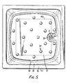
- Figure 5 is a plan of the system shown in Figure 4, the extent of the strengthening panel 40 being shown as a discontinuous line. Also, the gulley 18 is clearly shown, as is the manner in which it leads to the flat 12.
- the waste flange 1 has already been described in connection with Figure 1, and there is also shown a key 80 having a generally cylindrical body 81 with two arms 82 and six dependent lugs 31 capable of being introduced into the holes in the grid 3 of the waste flange 1, for rotating the waste flange 1 during assembly.
- a template (not shown, but provided by the supplier) can be placed on the floor 90 of the building and positioned correctly with respect to the effluent pipe 70.
- the waste body adaptor 20 can then be secured to the waste trap 30 by screwing the running nut 31 onto the screw thread 23, there being a seal to ensure no leakage.
- the waste trap 30 can be a conventional waste trap as obtained at a builders' merchant, and the waste body adaptor 24 is in accordance with the present invention.
- the combination of the two can be lowered into the channel 54 in the first support so that the projections 24 of the adaptor 20 are accommodated within the slots 55 of the first support 50.
- the effluent pipe 70 is then securely connected to 'the other end of the waste trap 30 by means of the running nut 71 engaging the screw thread 32.
- the first support 50 is then secured to the floor 9 0 of the building by means of the screws 58 located in the holes 57.
- the seal 25 is then placed on the upper part of the waste body adaptor 20.
- An advantage of the system of the present invention is that, should there be any blockage in, for instance, the waste trap 30, it is a simple matter to use the key 80 to release the waste flange 1 thereby providing clear access to the waste body adaptor 20 and thence to the waste trap-30.
- the system of the present invention provides easy installation together with positive support and positive location of the shower tray 10.
- the effluent pipe 70 and waste trap 30 can be conventional components acquired from a builders's merchant.
- a person wishing to install the shower tray can then purchase the system of shower tray, support means, waste adaptor and waste flange.
- the purchased package should include an appropriate template, screws for securing the support means to the floor of the building (or other suitable fixing means), and the necessary seals (for example seals 6 and 25).
- the effluent pipe 70 need not run directly rearwards, as shown in the illustrated embodiment. Instead, it can run along any desired line, in view of the permitted rotation of the first support 50 relative to the second support 60.
Abstract
Description
- This invention relates to a system of a shower tray and a waste and support for the shower tray; andto a waste body adaptor which is part of the system.
- Known, conventional shower trays have a drain hole in which a tail portion of a waste flange is located, the flange portion of the waste flange bearing on a seal which bears down on an upper surface of a flat portion of the floor of the shower tray adjacent the drain hole. The waste flange is held securely in position by means of a nut which engages an upper portion of an external thread on the tail portion of the waste flange, below the flat of the floor. The nut, when secured, causes the seal to be compressed thereby effecting an efficient seal.
- The waste includes a trap which is provided with a running nut which is intended to engage a lower portion of the external thread on the tail portion of the waste flange. In practice, especially with shower trays having an integral side wall, it can be extremely difficult to tighten the running nut, and it can also be difficult to ensure that there is adequate support under the floor of the shower tray; generally, the greater the amount of support, the greater the degree of obstruction so far as tightening the running nut is concerned.
- The problem of correctly installing a shower tray and its waste and support means can be greatly exacerbated when the shower tray is to be located in a recess defined by three walls with the waste means joining an effluent pipe which is inaccessible from the far side of one of the three walls.
- According to one aspect of the present invention, there is provided a system of a shower tray with waste and support means, the system being in dismantled, partially assembled or fully assembled form and comprising:
- a shower tray having a floor portion provided with a flat having a drain hole surrounded by a spigot dependent from the flat;
- support means capable of supporting the shower tray and having a channel for accommodating waste components below the shower tray;
- a waste flange which has a flange portion capable of resting on the flat of the shower tray and which has a tail portion having a threaded portion and capable of passing through the spigot of the shower tray; and
- a waste body adaptor having (a) means capable of resisting rotation of the adaptor relative to the support means, (b) a recess for accommodating a lower end region of the spigot of the shower tray, (c) a threaded portion for engagement with the complementary threaded portion on the tail portion of the waste flange, and (d) a portion suitable, in use, for securing engagement with a waste trap:
- the system being such that, when assembled, the spigot is accommodated in the recess (b) of the waste body adaptor, the flange portion of the waste flange rests on the flat of the shower tray, the tail portion of the waste flange passes through the spigot and securely engages the threaded portion (c) of the waste body adaptor, the means (a) cooperates with the support means to prevent rotation of the waste body adaptor, and the support means provides support for the shower tray.
- The system, which can be packaged and sold as a combination of components in assembled or dismantled form, may optionally include two seals, the first seal being intended to fit around the tail portion of the waste flange and, in use, to be positioned between the flange portion of the waste flange and the flat of the shower tray; and the second seal being intended to fit around the spigot of the shower tray and, in use, to be positioned between the underside of the flat of the shower tray and an upper face of the waste body adaptor.
- The support means may be, but does not necessarily need to be, in the form of two complementary components. The case in which the support means is in the form of two components is described in much greater detail hereinbelow.
- Another aspect of the present invention is the waste body adaptor itself. This aspect provides a waste body adaptor having threaded portions intended for connection to a waste trap and to a tail portion of a waste flange, with a floor portion of a shower tray between the waste body adaptor and the waste flange; wherein that region of the waste body adaptor which is to face the waste flange is provided with a recess for accommodating a spigot dependent from the floor portion of the shower tray; and wherein an external side wall region of the waste body adaptor is provided with at least one projection intended, when abutting a secure member, to resist rotation of the waste body adaptor when the flange is being secured thereto.
- The secure member referred to in the immediately preceding paragraph could be, in practice, part of the support means referred to as a component of the first-mentioned aspect of the present invention.
- The waste body adaptor which itself constitutes the second-mentioned aspect of the present invention can thus be regarded as an adaptor having (a) means for resisting rotation relative to a support means, (b) a recess for accommodating a lower end region of a spigot of a shower tray, (c) a threaded portion for engagement with a complementary threaded portion on a tail portion of a waste flange, and (d) a portion suitable, in use, for engagement with a waste trap.
- The provision of the spigot dependent from the flat of the shower tray is an important and novel feature of the shower tray which constitutes a component of the system of the present invention.
- In order to install the system constituting the first-mentioned aspect of the present invention, the support means (or at least one component thereof when the support means is constituted by two or more components) is correctly positioned, which can be accomplished with the aid of a template provided by the supplier. The template will enable the support means to be positioned correctly not only with regard to an effluent pipe (which may already be fixed in position by a builder), but also with regard to the area in which the shower tray is to be located so that the shower tray is located securely in the correct position.
- With the support means, or at least part of the support means,appropriately located and secured, for example by screws screwed into the floor of the building, a waste trap can be secured to the effluent pipe and the waste body adaptor can be secured with respect to the waste trap. In practice, the support means will have slots or other holes for locating the projections or other means on the waste bodya adaptor for resisting rotation relative to the support means.
- A seal, the second of the two aforementioned seals, can then be positioned on top of the waste body adaptor, and then the shower tray can be lowered into position. Depending on the nature of the support means already in position, the shower tray may be provided with one or more further component of support means secured to the underside of the shower tray so that, when the shower tray is lowered into the correct position, it has its floor portion adequately supported by virtue of the support means which by then rest(s) on the floor of the building.
- As the shower tray is lowered into position, the spigot of the shower tray is accommodated within the recess (b) of the waste body adaptor.
- With the shower tray thus correctly positioned and supported, a seal, the first of the two aforementioned seals, is located around the tail portion of the waste flange, and the tail portion is then passed down into the spigot of the shower tray. After passing through the spigot the threaded tail portion of the waste flange can, upon rotation of the waste flange, be caused to engage with the appropriate threaded portion (c) of the waste body adaptor.
- A key provided with a plurality of lugs which engage in the holes of a grid in the waste flange can be used for rotating the waste flange with respect to the waste body adaptor, so as to ensure a good seal in the region of the two seals.
- The shower tray forming part of the system of the present invention may have a thickness (prior to forming) of, for example, 4, 4.5 or 5 mm and may be formed from, for instance, so-called 10 percent acrylic on ABS. In this material, the acrylic can be PMMA (polymethylmethacrylate), and the ABS is a terpolymer of acrylonitrile, butadiene and styrene, the terpolymer occupying approximately 90% of the thickness of the material.
- The shower tray may have, but need not have, an integral side wall. The present invention is particularly advantageous for shower trays having an integral side wall in view of the limited accessibility to the underside of the shower tray, which has proved such a problem in the past.
- The shower tray can have the drain hole in any convenient position and is not limited to any particular position, although for aesthetic purposes and ease of plumbing, it is convenient to have the drain hole at the so-called centre back position.
- The shower tray may, in its floor region, be provided with some suitable anti-slip means, such as numerous small raised portions.
- The shower tray may, in addition, be provided with a gulley near the edge of the floor portion so that water drains from the floor portion into the gulley and is then led around the gulley to the drain hole, conveniently positioned at the centre back position.
- In addition to the support means referred to above and described in greater detail below, the underside of the tray may be provided with a strengthening plate which not only strengthens the floor portion of the shower tray but also serves to spread any load applied to the floor portion. The strengthening plate may be constructed of any convenient material, preferably a relatively inexpensive material, such as chipboard, for instance chipboard having a thickness of 12mm.
- The spigot which is dependent from the flat of the shower tray may extend downwardly by a distance in the range from 9.5 to 12.7mm below the underside of the flat. The flat is conveniently immediately adjacent the spigot.
- As regards the support means it is possible to employ a single support means and such a support means is contemplated within the scope of the invention.
- However, it is particularly convenient to employ a support means in the form of a first support and a second support, the first support being intended to be secured to the floor of the building before installation of the shower tray, and the second support being intended to be positioned at the time that the shower tray is installed. In fact, for convenience and security, the second support may be supplied by the supplier already secured to the underside of the shower tray, with the aforementioned strengthening plate between an upper portion of the second support and the underside of the floor of the shower tray.
- The first and second supports may be, and preferably are, complementary in that, apart from the channel for accommodating the waste components below the shower tray, the first and second supports occupy substantially the whole of the space'below the floor portion of the shower tray so as to provide full support for the shower tray.
- Preferably, but not necessarily the first support has the form of a truncated cone with the base of the cone having a larger diameter than the flat top of the cone, so that the side wall of the cone tapers upwardly. Conveniently the channel provided in the conical first support is in such a position that the axis of the conical first support can pass through the centre of the spigot of the shower tray, when those components are correctly positioned. The second support preferably then has a form which corresponds to the space below the shower tray apart from the conical shape of the first support and apart from any channel in the second support for an effluent pipe.
- The channel in the first support can be adpated to be suitable to accommodate a conventional 38mm (1.5 inch) diameter waste trap having a waste seal depth of 19 or 76mm (0.75 or 3inch). The advantage of having a circular conical form for the first support is that it can be rotated appropriately so that the waste body adaptor and waste trap can be correctly lined up with the effluent pipe, and the fact that the first support is of circular conical form means that it can be rotated relative to the second support without causing any undue problems, provided that the second support is in the correct position for accommodating the effluent pipe.
- The first support is preferably provided with means for securing the first support to the floor of the building. Thus, the first support may be provided with screw holes through which screws may be passed to secure the first support to the floor of the building.
- The first support can have, in addition to the aforementioned channel, slots or other recessed regions for accommodating the projections or other means which extend from the side wall of the waste body adaptor and which are intended to prevent rotation of the waste body adaptor relative to the first support.
- The support means, for example the first and second supports, can be formed from expanded polystyrene, for instance a high density expanded polystyrene.
- As regards the waste body adaptor this must, as indicated above, have (a) means for resisting rotation relative to the support means, for example projections in the form of wings from the side of the adaptor; (b) a recess for accommodating a lower end region of the spigot of the shower tray; (c) a threaded portion for engagement with a complementary threaded portion on the tail portion of the waste flange; and (d) a portion suitable, in use, for engagement with a waste trap. The waste body adaptor may be formed of a suitable injection moulded plastics material. It may have, for example, a height of 37mm, although the actual dimensions may be varied considerably depending on the dimensions of the waste flange, the waste trap, and the intended height between the floor portion of the shower tray and the floor of the building.
- As regards the waste flange, again the dimensions may be varied considerably depending on the size of the shower tray and the magnitude of the waste body adaptor. However, by way of example, a waste flange having a flange portion with a diameter of 74mm and a tail portion with a height of 25mm may be suitable.
- As regards the seal between the underside of the flange portion of the waste flange and the flat of the shower tray, this may be formed from, for instance, polypropylene.
- As regards the seal between the underside of the flat and the upper face of the waste body adaptor, this may be formed from, for example, a synthetic rubber material.
- For a better understanding of the present invention and to show how the same may be carried into effect, reference will now be made, by way of example, to the accompanying drawings, in which:
- Figure 1 shows, in exploded form, partially as a side view and partially as a vertical section, some of the components of one embodiment of the system of the present invention;
- Figure 2 shows, on a reduced scale and as an oblique view from above, the components shown in Figure 1 and also the first support;
- Figure 3 shows, on a further reduced scale and as a vertical section, a shower tray with strengthening means and the second support secured to the underside of the shower tray, the second support being complementary to the first support shown in Figure 2;
- Figure 4 is a vertical section through the same components as shown in Figure 3, but with the components shown in Figure 2 also present;
- Figure 5 is a plan of the system shown in Figure 4; and
- Figure 6 is a view, mainly from the side but slightly from above, of the waste flange shown in Figure 1 and of a key suitable for rotating the waste flange.
- Referring first to Figure 1, in the main, there is shown a waste flange generally indicated by the
reference 1, which has aflange portion 2, a grid 3 (shown most clearly in Figures 5 and 6), and adependent tail portion 4 provided over the majority of its length with anexternal screw thread 5. - Also shown in Figure 1 is a
seal 6, in this case a polypopylene seal, which is intended to surround the non-threaded portion of the tail portion of thewaste flange 1. - In Figure 1 only a small portion of the shower tray, generally indicated by the
reference numeral 10, is shown. The illustrated portion includes part of thefloor portion 11 which is provided with a slightly recessed flat 12 (for accommodating theflange portion 2 of the waste flange 1), dependent from which flat 12 is anintegral spigot 13, which defines a drain hole. - Other components of the
shower tray 10 will be described later hereineblow. - Also shown in Figure 1 is the waste body adaptor generally indicated as 20, which has an internal recess 21 intended to accommodate the
spigot 13 of theshower tray 10. An intermediate portion of the internal surface of thewaste body adaptor 20 is provided with ascrew thread 22 intended to engage thescrew thread 5 of thewaste flange 1. A lover region of thewaste body adpator 20 is provided with anexternal screw thread 23. Projecting diametrically from the upper and intermediate portions of the external side wall of thewaste body adaptor 20 are tworadial projections 24. - Shown resting on an upper portion of the
waste body adaptor 20 is aseal 25, in this case one formed of synthetic rubber, which is intended to provide a seal in the region between the upper part of thewaste body adaptor 20 and the underside of the flat 12 of theshower tray 10. - Also shown in Figure 1 is a waste trap generally indicated by the
reference numeral 30, which is provided at one end with a runningnut 31 and at the opposite end with ascrew thread 32. The runningnut 31 has an internal screw thread intended to engage theexternal screw thread 23 of thewaste body adaptor 20; and theexternal screw thread 32 is intended to be gripped by a runningnut 71 at the end of an effluent pipe 70 (shown in Figures 2 and 4). - Figure 2, in addition to showing on a reduced scale the components illustrated in Figure 1, shows a first support generally indicated by the
reference numeral 50, thefirst support 50 having a generallycircular base 51, a generally circulartop face 52 and an upwardly taperingside wall 53. Thesupport 50, which may-be formed from expanded polystyrene, is generally solid apart from: achannel 54 intended to accommodate waste cmponents, twoslots 55 intended to accommodate theprojections 24 of thewaste body adpator 20, two scooped outportions 56 and two screw holes 57 (only one of which is shown). - The
first support 50 is intended to support and locate thewaste body adaptor 20 andwaste trap 30, as well as supporting part of thefloor portion 11 of theshower tray 10. When correctly positioned on thefloor 90 of a building, perhaps with the aid of a template provided by the supplier, thefirst support 50 can be secured to thefloor 90 of the building by means ofscrews 58 which are secured through the screw holes 57. In this arrangement theprojections 24 on thewaste body adaptor 20 will be located in theslots 55, thereby preventing any rotation of thewaste body adaptor 20 relative to thewaste trap 30 when thewaste flange 1 is rotated with respect to theadaptor 20. - Figure 3 shows, in full, the
shower tray 10 with itsfloor portion 11, flat 12 andspigot 13. Also shown on thefloor portion 11 are raisedportions 14 to resist slipping. Thefloor portion 11 is surrounded by an inner, upward,side wall 15 at the top of which is arim 16 dependent from which is anouter side wall 17. At the foot of theinner side wall 15 is agulley 18 which communicates with the flat 12 so that water draining from thefloor portion 11 can be carried by thegulley 18 to the region of the flat 12 and, from there, down through the drain hole defined by thespigot 13. - Underneath a major portion of the
floor portion 11 is a strengtheningpanel 40 which, in this particular case, is secured to the underside of the floor portion 11 (although this need not be the case). - Also shown, and occupying a major portion of the space below the
shower tray 10 is thesecond support 60 which is provided with a largeconical void 61 the dimensions of which correspond to the corresponding external dimensions of thefirst support 50. In the embodiment illustrated (although this need not be the case) thesecond support 60 is secured to the underside of theshower tray 10, and may, like thefirst support 50, be formed of a high density expanded polystyrene. - Figure 4 shows the case in which the components illustrated in Figure 2 are accommodated within the
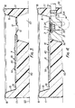
void 61 of thesecond support 60 shown in Figure 3. Thus Figure 4 is the equivalent to the combination of the components in Figure 2 (in assembled form) and those in Figure 3 (if one disregards theshower tray 10 of Figure 2). - It is clear from Figure 4 that the
waste body adaptor 20 and thewaste trap 30 are accommodated within thefirst support 50. Ansappropriate channel in thesecond support 60 and in an appropriate region of the right hand side wall 17 (as viewed in Figure 4)' is necessary to accommodate theeffluent pipe 70 and the runningnut 71. - In the event that a deep, as opposed to shallow, water seal is required, then it may well be necessary to provide a suitable pit within the
floor 90 of the building to accommodate a deep trap such as that shown bydiscontinuous lines 30A in Figure 4. - Figure 5 is a plan of the system shown in Figure 4, the extent of the strengthening
panel 40 being shown as a discontinuous line. Also, thegulley 18 is clearly shown, as is the manner in which it leads to the flat 12. - As regards Figure 6, the
waste flange 1 has already been described in connection with Figure 1, and there is also shown a key 80 having a generallycylindrical body 81 with twoarms 82 and sixdependent lugs 31 capable of being introduced into the holes in thegrid 3 of thewaste flange 1, for rotating thewaste flange 1 during assembly. - The method of installing the system illustrated in the drawings will now be described.
- Assuming that the
shower tray 10 is to be positioned in a particular place, which in practice may be determined by the position of an existingeffluent pipe 70, a template (not shown, but provided by the supplier) can be placed on thefloor 90 of the building and positioned correctly with respect to theeffluent pipe 70. - The
waste body adaptor 20 can then be secured to thewaste trap 30 by screwing the runningnut 31 onto thescrew thread 23, there being a seal to ensure no leakage. Thewaste trap 30 can be a conventional waste trap as obtained at a builders' merchant, and thewaste body adaptor 24 is in accordance with the present invention. - With the
waste body adaptor 20 and thewaste trap 30 secured together, the combination of the two can be lowered into thechannel 54 in the first support so that theprojections 24 of theadaptor 20 are accommodated within theslots 55 of thefirst support 50. - The
effluent pipe 70 is then securely connected to 'the other end of thewaste trap 30 by means of the runningnut 71 engaging thescrew thread 32. - The
first support 50 is then secured to the floor 90 of the building by means of thescrews 58 located in theholes 57. - The
seal 25 is then placed on the upper part of thewaste body adaptor 20. - The already combined assembly shown in Figure 3, namely the
shower tray 10, strengtheningpanel 40 andsecond support 60, is then lowered into position carefully so that thespigot 13 passes through theseal 25 and comes to rest in the recess 21 in the upper part of thewaste body adaptor 20. - As the assembly illustrated in Figure 3 is being lowered into position the
second support 60 moves down around thefirst support 50. Depending on the size of theeffluent pipe 70 and runningnut 71 it will be necessary for a channel of appropriate dimensions to be provided in the rear side wall and adjacent region of the second support 60 (i.e. at the right hand portion shown in Figures 3 and 4). - Once the assembly illustrated in Figure 3 is correctly and securely positioned with regard to the
first support 50 and thewaste body adaptor 20, theseal 6 is placed on the flat 12, and then thewaste flange 1 is lowered into position and rotated by means of the key 80 (shown in Figure 6) so that thescrew thread 5 on thetail portion 4 of thewaste flange 1 engages thescrew thread 22 in the intermediate portion of thewaste body adaptor 20. With thewaste flange 1 andwaste body adaptor 20 properly secured with respect to each other theseals - An advantage of the system of the present invention is that, should there be any blockage in, for instance, the
waste trap 30, it is a simple matter to use the key 80 to release thewaste flange 1 thereby providing clear access to thewaste body adaptor 20 and thence to the waste trap-30. - In addition to the accessibility of the waste trap 30 (by removal of the waste flange 1), the system of the present invention provides easy installation together with positive support and positive location of the
shower tray 10. - For do-it-yourself operations, which are becoming increasingly popular, the
effluent pipe 70 andwaste trap 30 can be conventional components acquired from a builders's merchant. A person wishing to install the shower tray can then purchase the system of shower tray, support means, waste adaptor and waste flange. The purchased package should include an appropriate template, screws for securing the support means to the floor of the building (or other suitable fixing means), and the necessary seals (forexample seals 6 and 25). - The
effluent pipe 70 need not run directly rearwards, as shown in the illustrated embodiment. Instead, it can run along any desired line, in view of the permitted rotation of thefirst support 50 relative to thesecond support 60.
Claims (21)
Priority Applications (1)
| Application Number | Priority Date | Filing Date | Title |
|---|---|---|---|
| AT82303736T ATE13919T1 (en) | 1981-10-29 | 1982-07-16 | SYSTEM FOR A SHOWER TRAY WITH DRAIN AND SUBSTRUCTURE. |
Applications Claiming Priority (2)
| Application Number | Priority Date | Filing Date | Title |
|---|---|---|---|
| GB08132649A GB2107979B (en) | 1981-10-29 | 1981-10-29 | Shower tray waste system |
| GB8132649 | 1981-10-29 |
Publications (2)
| Publication Number | Publication Date |
|---|---|
| EP0078593A1 true EP0078593A1 (en) | 1983-05-11 |
| EP0078593B1 EP0078593B1 (en) | 1985-06-19 |
Family
ID=10525482
Family Applications (1)
| Application Number | Title | Priority Date | Filing Date |
|---|---|---|---|
| EP82303736A Expired EP0078593B1 (en) | 1981-10-29 | 1982-07-16 | A system of a shower tray, waste and support |
Country Status (4)
| Country | Link |
|---|---|
| EP (1) | EP0078593B1 (en) |
| AT (1) | ATE13919T1 (en) |
| DE (1) | DE3264270D1 (en) |
| GB (1) | GB2107979B (en) |
Cited By (11)
| Publication number | Priority date | Publication date | Assignee | Title |
|---|---|---|---|---|
| GB2187939A (en) * | 1984-07-23 | 1987-09-23 | Bloomfield Ind Inc | Beverage-making device |
| AU651527B2 (en) * | 1992-06-19 | 1994-07-21 | Gregory John Mahoney | A plumbing fitting |
| GB2317107A (en) * | 1996-09-11 | 1998-03-18 | Coram | Shower tray having support means for the drainage hole area |
| GB2375479A (en) * | 2002-02-23 | 2002-11-20 | Beldore Ltd | Waste water outlet unit for a shower tray |
| EP1621688A1 (en) * | 2004-07-19 | 2006-02-01 | Terenzio Ligas | Method and tools for mounting an outlet fitting to a wash basin |
| DE102005013942A1 (en) * | 2004-12-23 | 2006-07-06 | Dallmer Gmbh & Co. Kg | Drainage device for the arrangement of a bottom plate with an opening for wastewater and arrangement of such a drainage device on a bottom plate |
| EP1973453A1 (en) | 2005-10-18 | 2008-10-01 | Impey (UK) Limited | Shower assemblies |
| US9267626B2 (en) | 2013-06-17 | 2016-02-23 | Emerson Electric Co. | Threaded sink flange assembly for installation of a food waste disposer to a sink |
| IT201900011799A1 (en) * | 2019-07-15 | 2021-01-15 | Pollini S R L | SHOWER TRAY AND RELATED PRODUCTION METHOD. |
| US10988919B2 (en) | 2018-11-20 | 2021-04-27 | Dlp Limited | Shower floor assembly |
| EP3913167A3 (en) * | 2020-05-20 | 2022-01-05 | Bestway Inflatables & Material Corp. | Drainage device for above-ground pool and above-ground pool |
Families Citing this family (3)
| Publication number | Priority date | Publication date | Assignee | Title |
|---|---|---|---|---|
| GB2126699B (en) * | 1982-09-02 | 1986-02-19 | Barker & Co George | Refrigerated display cabinets |
| GB8508733D0 (en) * | 1985-04-03 | 1985-05-09 | Armitage Shanks Ltd | Waste fitment |
| GB8824954D0 (en) * | 1988-10-25 | 1988-11-30 | Swindells J | Sealing device |
Citations (4)
| Publication number | Priority date | Publication date | Assignee | Title |
|---|---|---|---|---|
| GB873172A (en) * | 1956-12-06 | 1961-07-19 | Barking Brassware Company Ltd | Improvements in or relating to waste outlet fittings for sinks, wash-basins, baths and the like |
| DE2150158A1 (en) * | 1971-10-07 | 1973-04-19 | Jun Richard Killer | Detachable odour interceptor trap for sanitary ware - has an immersed tube sealing ring and bayonet lock |
| GB1508594A (en) * | 1975-05-19 | 1978-04-26 | Gardex Ltd | Shower base |
| GB1590791A (en) * | 1978-05-10 | 1981-06-10 | Foldor Ltd | Shower base |
-
1981
- 1981-10-29 GB GB08132649A patent/GB2107979B/en not_active Expired
-
1982
- 1982-07-16 EP EP82303736A patent/EP0078593B1/en not_active Expired
- 1982-07-16 DE DE8282303736T patent/DE3264270D1/en not_active Expired
- 1982-07-16 AT AT82303736T patent/ATE13919T1/en not_active IP Right Cessation
Patent Citations (4)
| Publication number | Priority date | Publication date | Assignee | Title |
|---|---|---|---|---|
| GB873172A (en) * | 1956-12-06 | 1961-07-19 | Barking Brassware Company Ltd | Improvements in or relating to waste outlet fittings for sinks, wash-basins, baths and the like |
| DE2150158A1 (en) * | 1971-10-07 | 1973-04-19 | Jun Richard Killer | Detachable odour interceptor trap for sanitary ware - has an immersed tube sealing ring and bayonet lock |
| GB1508594A (en) * | 1975-05-19 | 1978-04-26 | Gardex Ltd | Shower base |
| GB1590791A (en) * | 1978-05-10 | 1981-06-10 | Foldor Ltd | Shower base |
Cited By (15)
| Publication number | Priority date | Publication date | Assignee | Title |
|---|---|---|---|---|
| GB2187939A (en) * | 1984-07-23 | 1987-09-23 | Bloomfield Ind Inc | Beverage-making device |
| AU651527B2 (en) * | 1992-06-19 | 1994-07-21 | Gregory John Mahoney | A plumbing fitting |
| GB2317107A (en) * | 1996-09-11 | 1998-03-18 | Coram | Shower tray having support means for the drainage hole area |
| GB2317107B (en) * | 1996-09-11 | 2000-06-07 | Coram | Shower tray |
| US6890427B2 (en) | 2002-02-23 | 2005-05-10 | Dlp Limited | Waste water outlet unit |
| GB2375479B (en) * | 2002-02-23 | 2003-03-26 | Beldore Ltd | Waste water outlet unit |
| GB2375479A (en) * | 2002-02-23 | 2002-11-20 | Beldore Ltd | Waste water outlet unit for a shower tray |
| EP1621688A1 (en) * | 2004-07-19 | 2006-02-01 | Terenzio Ligas | Method and tools for mounting an outlet fitting to a wash basin |
| DE102005013942A1 (en) * | 2004-12-23 | 2006-07-06 | Dallmer Gmbh & Co. Kg | Drainage device for the arrangement of a bottom plate with an opening for wastewater and arrangement of such a drainage device on a bottom plate |
| EP1973453A1 (en) | 2005-10-18 | 2008-10-01 | Impey (UK) Limited | Shower assemblies |
| US9267626B2 (en) | 2013-06-17 | 2016-02-23 | Emerson Electric Co. | Threaded sink flange assembly for installation of a food waste disposer to a sink |
| US10988919B2 (en) | 2018-11-20 | 2021-04-27 | Dlp Limited | Shower floor assembly |
| IT201900011799A1 (en) * | 2019-07-15 | 2021-01-15 | Pollini S R L | SHOWER TRAY AND RELATED PRODUCTION METHOD. |
| EP3913167A3 (en) * | 2020-05-20 | 2022-01-05 | Bestway Inflatables & Material Corp. | Drainage device for above-ground pool and above-ground pool |
| US11555320B2 (en) | 2020-05-20 | 2023-01-17 | Bestway Inflatables & Material Corp. | Drainage device for above-ground pool and above-ground pool |
Also Published As
| Publication number | Publication date |
|---|---|
| GB2107979B (en) | 1985-05-01 |
| DE3264270D1 (en) | 1985-07-25 |
| GB2107979A (en) | 1983-05-11 |
| EP0078593B1 (en) | 1985-06-19 |
| ATE13919T1 (en) | 1985-07-15 |
Similar Documents
| Publication | Publication Date | Title |
|---|---|---|
| EP0078593B1 (en) | A system of a shower tray, waste and support | |
| US5329971A (en) | Closet flange test plug | |
| US4827539A (en) | Adjustable closet floor flange | |
| US4694513A (en) | Drain | |
| US4780915A (en) | Toilet floor flange | |
| US7055184B2 (en) | Closet flange with knockout retainer | |
| US20090172877A1 (en) | Means for Covering the Flange of a Waste Water Strainer | |
| US4943100A (en) | Drain suited for installation in wooden floors | |
| US11591787B2 (en) | Adjustable floor drain and method of installation | |
| US4871451A (en) | Floor drain plate assembly | |
| US4515398A (en) | Device for elevating closet bowl | |
| US20110209279A1 (en) | Means for Covering the Flange of a Waste Water Strainer | |
| US6725468B2 (en) | Combination plug device and cover plate | |
| CA2298921A1 (en) | Shower drain | |
| US3339215A (en) | Self-retaining closet bolt | |
| US4175292A (en) | Sink mounting means | |
| US5249697A (en) | Meter pit | |
| US3967326A (en) | Flange assembly for installing a toilet fixture | |
| US3419288A (en) | Stabilizer for polymer composition pipe | |
| US20050034227A1 (en) | Toilet flange assembly | |
| US4433446A (en) | Flush valve attachment system | |
| JP5019684B2 (en) | Underfloor piping structure | |
| US3921229A (en) | Water closet ring | |
| US5347786A (en) | Reusable concrete spacer sleeve | |
| CA2288035A1 (en) | Method and means for covering the flange of a waste water strainer |
Legal Events
| Date | Code | Title | Description |
|---|---|---|---|
| PUAI | Public reference made under article 153(3) epc to a published international application that has entered the european phase |
Free format text: ORIGINAL CODE: 0009012 |
|
| AK | Designated contracting states |
Designated state(s): AT BE CH DE FR IT LI LU NL SE |
|
| 17P | Request for examination filed |
Effective date: 19831101 |
|
| GRAA | (expected) grant |
Free format text: ORIGINAL CODE: 0009210 |
|
| AK | Designated contracting states |
Designated state(s): AT BE CH DE FR IT LI LU NL SE |
|
| PG25 | Lapsed in a contracting state [announced via postgrant information from national office to epo] |
Ref country code: SE Free format text: THE PATENT HAS BEEN ANNULLED BY A DECISION OF A NATIONAL AUTHORITY Effective date: 19850619 Ref country code: LI Effective date: 19850619 Ref country code: IT Free format text: LAPSE BECAUSE OF FAILURE TO SUBMIT A TRANSLATION OF THE DESCRIPTION OR TO PAY THE FEE WITHIN THE PRESCRIBED TIME-LIMIT;WARNING: LAPSES OF ITALIAN PATENTS WITH EFFECTIVE DATE BEFORE 2007 MAY HAVE OCCURRED AT ANY TIME BEFORE 2007. THE CORRECT EFFECTIVE DATE MAY BE DIFFERENT FROM THE ONE RECORDED. Effective date: 19850619 Ref country code: CH Effective date: 19850619 |
|
| REF | Corresponds to: |
Ref document number: 13919 Country of ref document: AT Date of ref document: 19850715 Kind code of ref document: T |
|
| REF | Corresponds to: |
Ref document number: 3264270 Country of ref document: DE Date of ref document: 19850725 |
|
| PG25 | Lapsed in a contracting state [announced via postgrant information from national office to epo] |
Ref country code: LU Free format text: LAPSE BECAUSE OF NON-PAYMENT OF DUE FEES Effective date: 19850731 |
|
| ET | Fr: translation filed | ||
| REG | Reference to a national code |
Ref country code: CH Ref legal event code: PL |
|
| PLBE | No opposition filed within time limit |
Free format text: ORIGINAL CODE: 0009261 |
|
| STAA | Information on the status of an ep patent application or granted ep patent |
Free format text: STATUS: NO OPPOSITION FILED WITHIN TIME LIMIT |
|
| PGFP | Annual fee paid to national office [announced via postgrant information from national office to epo] |
Ref country code: AT Payment date: 19860522 Year of fee payment: 5 |
|
| 26N | No opposition filed | ||
| PGFP | Annual fee paid to national office [announced via postgrant information from national office to epo] |
Ref country code: NL Payment date: 19860731 Year of fee payment: 5 |
|
| PG25 | Lapsed in a contracting state [announced via postgrant information from national office to epo] |
Ref country code: AT Effective date: 19870716 |
|
| BERE | Be: lapsed |
Owner name: PLASTIC FINISHES LTD Effective date: 19870731 |
|
| PG25 | Lapsed in a contracting state [announced via postgrant information from national office to epo] |
Ref country code: NL Effective date: 19880201 |
|
| NLV4 | Nl: lapsed or anulled due to non-payment of the annual fee | ||
| PG25 | Lapsed in a contracting state [announced via postgrant information from national office to epo] |
Ref country code: FR Free format text: LAPSE BECAUSE OF NON-PAYMENT OF DUE FEES Effective date: 19880331 |
|
| PG25 | Lapsed in a contracting state [announced via postgrant information from national office to epo] |
Ref country code: DE Effective date: 19880401 |
|
| REG | Reference to a national code |
Ref country code: FR Ref legal event code: ST |
|
| PG25 | Lapsed in a contracting state [announced via postgrant information from national office to epo] |
Ref country code: BE Effective date: 19890731 |