EP0078030A2 - Electric lamp - Google Patents
Electric lamp Download PDFInfo
- Publication number
- EP0078030A2 EP0078030A2 EP82109755A EP82109755A EP0078030A2 EP 0078030 A2 EP0078030 A2 EP 0078030A2 EP 82109755 A EP82109755 A EP 82109755A EP 82109755 A EP82109755 A EP 82109755A EP 0078030 A2 EP0078030 A2 EP 0078030A2
- Authority
- EP
- European Patent Office
- Prior art keywords
- metal cap
- lamp
- base sleeve
- base
- wire end
- Prior art date
- Legal status (The legal status is an assumption and is not a legal conclusion. Google has not performed a legal analysis and makes no representation as to the accuracy of the status listed.)
- Granted
Links
Images
Classifications
-
- H—ELECTRICITY
- H01—ELECTRIC ELEMENTS
- H01J—ELECTRIC DISCHARGE TUBES OR DISCHARGE LAMPS
- H01J5/00—Details relating to vessels or to leading-in conductors common to two or more basic types of discharge tubes or lamps
- H01J5/50—Means forming part of the tube or lamps for the purpose of providing electrical connection to it
- H01J5/54—Means forming part of the tube or lamps for the purpose of providing electrical connection to it supported by a separate part, e.g. base
-
- H—ELECTRICITY
- H01—ELECTRIC ELEMENTS
- H01K—ELECTRIC INCANDESCENT LAMPS
- H01K1/00—Details
- H01K1/42—Means forming part of the lamp for the purpose of providing electrical connection, or support for, the lamp
- H01K1/46—Means forming part of the lamp for the purpose of providing electrical connection, or support for, the lamp supported by a separate part, e.g. base, cap
Definitions
- the invention relates to an electric lamp with a lamp base, which is fastened via a metal cap that engages the lamp pinch foot, is inserted into the base sleeve and is firmly connected to it.
- the base can have a corresponding number of ground contacts. If there is only one central contact with the ground, the base sleeve must be included as a side contact and the end of the current supply wire in question must be guided between the metal cap and the base sleeve and fixed there.
- the object of the invention is to ensure an adjustment of the lamp even when the base sleeve has to serve as a side contact and the above measure is necessary for this.
- the metal cap is smaller in diameter than the minimum diameter of the base sleeve and is provided with an edge groove in which the power supply wire end placed between the metal cap and base sleeve runs.
- the lamp in FIG. 1 a halogen incandescent lamp, has a lamp bulb 1 made of high-melting glass.
- a tungsten filament 2 serves as the luminous element.
- the bulb 1 is filled with inert gas with halogen addition and is closed at the lower end by squeezing.
- Power supply wires 3 lead through the pinch foot 4 to the outside.
- a metal cap 5 engages on the pinch foot 4.
- the pinch foot 4 is received from its opening 6. With inwardly bent tabs 7 (FIG. 3), the metal cap 5 is supported on projections 8 of the crushed glass.
- the metal cap 5 is cylindrical. Also cylindrical is the lamp base 9, in the metal base sleeve 10 of which the metal cap 5 is inserted with a predetermined play.
- the base of the sleeve forms a base stone 11 and a central base contact 12.
- the base sleeve 10 is a side contact. Accordingly, one of the two power supply wires 3 leads to the ground contact 12, the other, however, is guided with its end 3a between the metal cap 5 and the base sleeve 10.
- the wire end 3a is inserted into an edge groove 13 of the metal cap 5.
- the edge groove 13 runs approximately parallel to the base axis.
- Another edge groove 14 is provided which is diametrically opposite the first.
Abstract
Die Metallkappe (5), die am Quetschfuß (4) der Lampe (1) angreift und die Sockelhülse (10) trägt, weist zur Aufnahme eines Stromzuführungsdrahtendes (3a) eine Nut (14) auf, wenn die Sockelhülse (10) elektrischer Seitenkontakt ist. Mit dem Anordnen des Drahtendes (3a) in der Nut (14) wird vermieden, daß durch das Drahtende (3a) das Justieren der zusammen mit ihrer Metallkappe (5) in die Sockelhülse (10) eingesetzten Lampe (1) gegenüber der Sockelhülse (10) behindert ist.The metal cap (5), which engages on the pinch foot (4) of the lamp (1) and carries the base sleeve (10), has a groove (14) for receiving a power supply wire end (3a) when the base sleeve (10) is an electrical side contact . By arranging the wire end (3a) in the groove (14) it is avoided that the wire end (3a) adjusts the lamp (1) inserted into the base sleeve (10) together with its metal cap (5) relative to the base sleeve (10 ) is disabled.
Description
Die Erfindung betrifft eine elektrische Lampe mit einem Lampensockel, der über eine am Lampenquetschfuß angreifende, in die Sockelhülse eingeführte und mit dieser fest verbundenen Metallkappe befestigt ist. Zum elektrischen Anschluß der Lampenstromzuführungsdrähte kann der Sockel eine entsprechende Anzahl Bodenkontakte aufweisen. Bei nur einem zentralen Bodenkontakt ist die Sockelhülse als Seitenkontakt einzubeziehen und das Ende des in Frage kommenden Stromzuführungsdrahtes zwischen Metallkappe und Sockelhülse zu führen und dort festzulegen.The invention relates to an electric lamp with a lamp base, which is fastened via a metal cap that engages the lamp pinch foot, is inserted into the base sleeve and is firmly connected to it. For the electrical connection of the lamp power supply wires, the base can have a corresponding number of ground contacts. If there is only one central contact with the ground, the base sleeve must be included as a side contact and the end of the current supply wire in question must be guided between the metal cap and the base sleeve and fixed there.
Aufgabe der Erfindung ist es, ein Justieren der Lampe auch dann zu gewährleisten, wenn die Sockelhülse als Seitenkontakt zu dienen hat und hierzu die vorstehende Maßnahme erforderlich ist.The object of the invention is to ensure an adjustment of the lamp even when the base sleeve has to serve as a side contact and the above measure is necessary for this.
Die gestellte Aufgabe wird dadurch gelöst, daß die Metallkappe im Durchmesser kleiner als der Mindestdurchmesser der Sockelhülse und mit einer Randnut versehen ist, in der das zwischen Metallkappe und Sockelhülse gelegte Stromzuführungsdrahtende verläuft.The object is achieved in that the metal cap is smaller in diameter than the minimum diameter of the base sleeve and is provided with an edge groove in which the power supply wire end placed between the metal cap and base sleeve runs.
Im folgenden wird die Erfindung anhand eines Ausführungsbeispiels näher beschrieben. Es zeigen
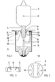
Figur 1 eine gesockelte elektrische LampeFigur 2 die Metallkappe in Draufsicht- Figur 3 die Metallkappe im Schnitt.
- Figure 1 is a socketed electric lamp
- Figure 2 shows the metal cap in plan view
- Figure 3 shows the metal cap in section.
Die Lampe der Figur 1, eine Halogenglühlampe, weist einen Lampenkolben 1 aus hochschmelzendem Glas auf. Als Leuchtkörper dient eine Wolframwendel 2. Der Kolben 1 ist mit Inertgas mit Halogenzusatz gefüllt und am unteren Ende durch Quetschen verschlossen. Stromzuführungsdrähte 3 führen durch den Quetschfuß 4 nach außen. Am Quetschfuß 4 greift eine Metallkappe 5 an. Von ihrer Öffnung 6 ist der Quetschfuß 4 aufgenommen. Mit nach innen gebogenen Lappen 7 (Figur 3) stützt sich die Metallkappe 5 an Vorsprüngen 8 des Quetschungsglases ab. Die Metallkappe 5 ist zylindrisch. Zylindrisch ist auch der Lampensockel 9, in dessen metallische Sockelhülse 10 die Metallkappe 5 mit vorgegebenem Spiel eingeführt ist. Den Hülsenboden bilden Sockelstein 11 und ein zentraler Bodenkontakt 12. Die Sockelhülse 10 ist Seitenkontakt. Entsprechend ist einer der beiden Stromzuführungsdrähte 3 zum Bodenkontakt 12, der andere dagegen mit seinem Ende 3a zwischen Metallkappe 5 und Sockelhülse 10 geführt. Das Drahtende 3a ist eingelegt in eine Randnut 13 der Metallkappe 5. Die Randnut 13 verläuft etwa parallel zur Sockelachse. Eine weitere Randnut 14 ist vorgesehen, die der ersten diametral gegenüberliegt. Nach dem Justieren werden durch Ausnutzen des vorgegebenen Spiels zwischen Metallkappe und Sockelhülse dort die justierte Lampe und der Seitenkontakt mittels Lot 16 ringförmig mit der Sockelhülse 10 verlötet.The lamp in FIG. 1, a halogen incandescent lamp, has a
Claims (1)
Applications Claiming Priority (2)
| Application Number | Priority Date | Filing Date | Title |
|---|---|---|---|
| DE19818131006U DE8131006U1 (en) | 1981-10-23 | 1981-10-23 | ELECTRIC LAMP |
| DE8131006U | 1981-10-23 |
Publications (3)
| Publication Number | Publication Date |
|---|---|
| EP0078030A2 true EP0078030A2 (en) | 1983-05-04 |
| EP0078030A3 EP0078030A3 (en) | 1983-11-09 |
| EP0078030B1 EP0078030B1 (en) | 1986-10-01 |
Family
ID=6732374
Family Applications (1)
| Application Number | Title | Priority Date | Filing Date |
|---|---|---|---|
| EP82109755A Expired EP0078030B1 (en) | 1981-10-23 | 1982-10-22 | Electric lamp |
Country Status (3)
| Country | Link |
|---|---|
| US (1) | US4489252A (en) |
| EP (1) | EP0078030B1 (en) |
| DE (2) | DE8131006U1 (en) |
Cited By (2)
| Publication number | Priority date | Publication date | Assignee | Title |
|---|---|---|---|---|
| FR2558009A1 (en) * | 1984-01-09 | 1985-07-12 | Philips Nv | ELECTRIC LAMP HAVING A PINCH APPLIED IN A SLEEVE SHAPE |
| US4870546A (en) * | 1987-12-15 | 1989-09-26 | Bosch-Siemens Hausgerate Gmbh | Electric lighting device for household appliances such as ovens |
Families Citing this family (9)
| Publication number | Priority date | Publication date | Assignee | Title |
|---|---|---|---|---|
| DE8311269U1 (en) * | 1983-04-15 | 1984-09-20 | Patent-Treuhand-Gesellschaft für elektrische Glühlampen mbH, 8000 München | LAMP FOR BAYONET-LIKE INSTALLATION IN A DISPLAY DEVICE |
| JPS63451U (en) * | 1986-06-20 | 1988-01-05 | ||
| JPH08264162A (en) * | 1995-03-22 | 1996-10-11 | Koito Mfg Co Ltd | Incandescent lamp and its manufacture |
| DE19709928A1 (en) * | 1997-03-11 | 1998-09-17 | Patent Treuhand Ges Fuer Elektrische Gluehlampen Mbh | Halogen light bulb and socket |
| WO1999067810A1 (en) * | 1998-06-22 | 1999-12-29 | Koninklijke Philips Electronics N.V. | Electric lamp with a comparatively robust lamp cap |
| US6628054B1 (en) * | 2000-10-13 | 2003-09-30 | General Electric Company | Base for low pressure discharge lamps |
| US6791250B2 (en) * | 2002-10-23 | 2004-09-14 | Eye Lighting International | Seal and flag assembly for lamp base sidewire welding |
| DE10306584A1 (en) * | 2003-02-17 | 2004-08-26 | Patent-Treuhand-Gesellschaft für elektrische Glühlampen mbH | Low-pressure discharge lamp |
| WO2008032259A2 (en) * | 2006-09-13 | 2008-03-20 | Philips Intellectual Property & Standards Gmbh | Lamp for a light system and clamping plate |
Citations (3)
| Publication number | Priority date | Publication date | Assignee | Title |
|---|---|---|---|---|
| US1957708A (en) * | 1931-04-24 | 1934-05-08 | Westinghouse Lamp Co | Mechanical base |
| US3622947A (en) * | 1970-09-02 | 1971-11-23 | Robert M Griffin | Lamp base extension |
| EP0024060A1 (en) * | 1979-08-11 | 1981-02-18 | Philips Patentverwaltung GmbH | Electric lamp with a socket-form base |
Family Cites Families (4)
| Publication number | Priority date | Publication date | Assignee | Title |
|---|---|---|---|---|
| US3573534A (en) * | 1968-10-28 | 1971-04-06 | Gen Electric | Lamp base and leading-in wire connection |
| JPS54129770A (en) * | 1978-03-30 | 1979-10-08 | Toshiba Corp | Lamp |
| DE2836596A1 (en) * | 1978-08-21 | 1980-03-13 | Patra Patent Treuhand | ELECTRIC LAMP |
| DE2938189C2 (en) * | 1979-09-21 | 1984-07-26 | Patent-Treuhand-Gesellschaft für elektrische Glühlampen mbH, 8000 München | Incandescent lamp with lamp base attached to the pinch foot without putty |
-
1981
- 1981-10-23 DE DE19818131006U patent/DE8131006U1/en not_active Expired
-
1982
- 1982-09-10 US US06/416,633 patent/US4489252A/en not_active Expired - Lifetime
- 1982-10-22 DE DE8282109755T patent/DE3273587D1/en not_active Expired
- 1982-10-22 EP EP82109755A patent/EP0078030B1/en not_active Expired
Patent Citations (3)
| Publication number | Priority date | Publication date | Assignee | Title |
|---|---|---|---|---|
| US1957708A (en) * | 1931-04-24 | 1934-05-08 | Westinghouse Lamp Co | Mechanical base |
| US3622947A (en) * | 1970-09-02 | 1971-11-23 | Robert M Griffin | Lamp base extension |
| EP0024060A1 (en) * | 1979-08-11 | 1981-02-18 | Philips Patentverwaltung GmbH | Electric lamp with a socket-form base |
Cited By (2)
| Publication number | Priority date | Publication date | Assignee | Title |
|---|---|---|---|---|
| FR2558009A1 (en) * | 1984-01-09 | 1985-07-12 | Philips Nv | ELECTRIC LAMP HAVING A PINCH APPLIED IN A SLEEVE SHAPE |
| US4870546A (en) * | 1987-12-15 | 1989-09-26 | Bosch-Siemens Hausgerate Gmbh | Electric lighting device for household appliances such as ovens |
Also Published As
| Publication number | Publication date |
|---|---|
| EP0078030B1 (en) | 1986-10-01 |
| DE3273587D1 (en) | 1986-11-06 |
| DE8131006U1 (en) | 1983-04-07 |
| EP0078030A3 (en) | 1983-11-09 |
| US4489252A (en) | 1984-12-18 |
Similar Documents
| Publication | Publication Date | Title |
|---|---|---|
| EP0078030A2 (en) | Electric lamp | |
| DE4012684A1 (en) | Compact low-pressure discharge lamp with switching arrangement | |
| EP0498256A2 (en) | Single-cap lamp | |
| EP0854496B1 (en) | Compact low pressure discharge lamp | |
| EP0854497A2 (en) | Compact low pressure discharge lamp | |
| EP1147534B1 (en) | Discharge lamp | |
| DE700996C (en) | Multipole threaded base and corresponding threaded electrical lamps | |
| EP1298703B1 (en) | Reflector lamp | |
| EP0923105B1 (en) | Compact low pressure discharge lamp | |
| EP0529146B1 (en) | Coil for the electromagnetic control of a switch apparatus | |
| DE836376C (en) | Light signaling device for electrical devices, especially switches of all kinds | |
| DE3346397A1 (en) | ADAPTATION BODY | |
| DE3615059A1 (en) | Lighting unit for electric switches | |
| EP1329932B1 (en) | Compact low pressure discharge lamp | |
| DE7934879U1 (en) | BASE SLEEVE FOR ELECTRIC BULBS | |
| EP0084848A2 (en) | Halogen incandescent lamp | |
| DE556599C (en) | Contact-proof lamp holder made of insulating material | |
| EP0179251A2 (en) | Mercury vapour low-pressure discharge lamp having a single base | |
| DE803918C (en) | Socket for electric light bulbs, especially in mine hand lamps | |
| DE45697C (en) | Innovations in electrical switches | |
| EP0906645B1 (en) | Printed circuit board with socket and base for a small incandescent lamp | |
| DE521557C (en) | Incandescent lamp socket with a two-part housing made of insulating material | |
| DE390046C (en) | Terminal locking screw plugs | |
| DE374793C (en) | Insulating socket for electric light bulbs | |
| DE327001C (en) | An electric flashlight that can be used as an alarm device is hung on the door handle and activated by pressing it down |
Legal Events
| Date | Code | Title | Description |
|---|---|---|---|
| PUAI | Public reference made under article 153(3) epc to a published international application that has entered the european phase |
Free format text: ORIGINAL CODE: 0009012 |
|
| AK | Designated contracting states |
Designated state(s): DE FR GB IT |
|
| PUAL | Search report despatched |
Free format text: ORIGINAL CODE: 0009013 |
|
| AK | Designated contracting states |
Designated state(s): DE FR GB IT |
|
| 17P | Request for examination filed |
Effective date: 19840410 |
|
| GRAA | (expected) grant |
Free format text: ORIGINAL CODE: 0009210 |
|
| AK | Designated contracting states |
Kind code of ref document: B1 Designated state(s): DE FR GB IT |
|
| ITF | It: translation for a ep patent filed |
Owner name: JACOBACCI & PERANI S.P.A. |
|
| REF | Corresponds to: |
Ref document number: 3273587 Country of ref document: DE Date of ref document: 19861106 |
|
| ET | Fr: translation filed | ||
| PLBE | No opposition filed within time limit |
Free format text: ORIGINAL CODE: 0009261 |
|
| STAA | Information on the status of an ep patent application or granted ep patent |
Free format text: STATUS: NO OPPOSITION FILED WITHIN TIME LIMIT |
|
| 26N | No opposition filed | ||
| ITTA | It: last paid annual fee | ||
| PGFP | Annual fee paid to national office [announced via postgrant information from national office to epo] |
Ref country code: GB Payment date: 20011016 Year of fee payment: 20 |
|
| PGFP | Annual fee paid to national office [announced via postgrant information from national office to epo] |
Ref country code: FR Payment date: 20011031 Year of fee payment: 20 |
|
| PGFP | Annual fee paid to national office [announced via postgrant information from national office to epo] |
Ref country code: DE Payment date: 20011217 Year of fee payment: 20 |
|
| REG | Reference to a national code |
Ref country code: GB Ref legal event code: IF02 |
|
| PG25 | Lapsed in a contracting state [announced via postgrant information from national office to epo] |
Ref country code: GB Free format text: LAPSE BECAUSE OF EXPIRATION OF PROTECTION Effective date: 20021021 |
|
| REG | Reference to a national code |
Ref country code: GB Ref legal event code: PE20 Effective date: 20021021 |