EP0077360B1 - Mit überspannungsschutzeinrichtungen versehener teilnehmerfernsprechapparat - Google Patents
Mit überspannungsschutzeinrichtungen versehener teilnehmerfernsprechapparat Download PDFInfo
- Publication number
- EP0077360B1 EP0077360B1 EP82901310A EP82901310A EP0077360B1 EP 0077360 B1 EP0077360 B1 EP 0077360B1 EP 82901310 A EP82901310 A EP 82901310A EP 82901310 A EP82901310 A EP 82901310A EP 0077360 B1 EP0077360 B1 EP 0077360B1
- Authority
- EP
- European Patent Office
- Prior art keywords
- transistor
- circuit
- base
- dipole
- emitter
- Prior art date
- Legal status (The legal status is an assumption and is not a legal conclusion. Google has not performed a legal analysis and makes no representation as to the accuracy of the status listed.)
- Expired
Links
Images
Classifications
-
- H—ELECTRICITY
- H04—ELECTRIC COMMUNICATION TECHNIQUE
- H04M—TELEPHONIC COMMUNICATION
- H04M1/00—Substation equipment, e.g. for use by subscribers
- H04M1/26—Devices for calling a subscriber
- H04M1/30—Devices which can set up and transmit only one digit at a time
- H04M1/31—Devices which can set up and transmit only one digit at a time by interrupting current to generate trains of pulses; by periodically opening and closing contacts to generate trains of pulses
- H04M1/312—Devices which can set up and transmit only one digit at a time by interrupting current to generate trains of pulses; by periodically opening and closing contacts to generate trains of pulses pulses produced by electronic circuits
-
- H—ELECTRICITY
- H02—GENERATION; CONVERSION OR DISTRIBUTION OF ELECTRIC POWER
- H02H—EMERGENCY PROTECTIVE CIRCUIT ARRANGEMENTS
- H02H9/00—Emergency protective circuit arrangements for limiting excess current or voltage without disconnection
- H02H9/02—Emergency protective circuit arrangements for limiting excess current or voltage without disconnection responsive to excess current
- H02H9/026—Current limitation using PTC resistors, i.e. resistors with a large positive temperature coefficient
-
- H—ELECTRICITY
- H02—GENERATION; CONVERSION OR DISTRIBUTION OF ELECTRIC POWER
- H02H—EMERGENCY PROTECTIVE CIRCUIT ARRANGEMENTS
- H02H9/00—Emergency protective circuit arrangements for limiting excess current or voltage without disconnection
- H02H9/04—Emergency protective circuit arrangements for limiting excess current or voltage without disconnection responsive to excess voltage
- H02H9/042—Emergency protective circuit arrangements for limiting excess current or voltage without disconnection responsive to excess voltage comprising means to limit the absorbed power or indicate damaged over-voltage protection device
Definitions
- the present invention relates to a subscriber telephone set provided, on the one hand, with a first surge protection device, connected in said set, to the line inputs, and on the other hand, with a second protection, arranged downstream of the handset hook, intended to limit the power applied to an electronic transmission and numbering circuit which cooperates with a dialing switch and a keypad.
- a surge limiter connected in parallel to the ends of the line wires which, operating in the manner of a Zener diode, is responsible for opposing an increase in the line voltage above a chosen threshold, by absorption of current on the line.
- Such an electronic protection circuit is incapable of completely protecting a subscriber telephone set because it cannot withstand large overvoltages such as those which may result, for example, from the accidental contact of a telephone line with a distribution cable. of electricity.
- Passive means such as resistors with a voltage coefficient (VDR) and resistors with a positive temperature coefficient (PTC) allow inexpensive and effective protection. It suffices, in fact, to have at the input of the subscriber station two PTC resistors in series in each of the line conductors and a VDR in parallel downstream of these. In the presence of a line overvoltage, the resistance of the VDR drops sharply, which causes a large current to flow in the PTCs, the heating of which considerably increases the line impedance.
- VDR voltage coefficient
- PTC positive temperature coefficient
- the protection thus obtained is not complete in the case where the subscriber station is provided with electronic circuits; it is known, in fact, that the procedure for calling a subscriber station from the central office is carried out by applying to the line an alternating voltage at 50 Hz of the order of 70 to 80 volts. After lifting the handset, the DC line voltage is approximately 10 volts, from which the various electronic circuits of the subscriber station are supplied.
- the "bend" voltage of the VDR must not be less than a certain volts, which means that an overvoltage below this value can be applied , in the "off-hook" position of the handset, to the electronic circuits of the subscriber unit without the protection means reacting.
- the electronic circuits are provided with internal means for limiting and stabilizing the supply voltage, the fact remains that a prolonged overvoltage can lead to the destruction of one or more circuits by overcurrent.
- One of the aims of the invention is to protect a subscriber station against all the possibilities of disturbance or destruction resulting from an overvoltage of any value.
- Another object of the invention is to take advantage of one of the embodiments of the protection device to carry out the numbering procedure by periodic cuts in the line current.
- a subscriber telephone set provided, on the one hand, with a first surge protection device, connected in said set, to the line inputs, and on the other hand, with a second device protection, arranged downstream of the handset hook, intended to limit the power applied to an electronic transmission and numbering circuit, which cooperates with a numbering switch and a keypad, is notably remarkable in that said second device protection consists of a dipole electronic circuit connected in series to one of the inputs of said transmission and numbering circuit, this dipole circuit comprising a first transistor whose emitter-collector path is connected to one of the terminals of the dipole, called the output terminal, by a current measurement resistor, and to the another terminal of the dipole, called the input terminal, by a diode forming with a second transistor, of opposite polarity to that of the first transistor, a current mirror which feeds, by the collector of this second transistor, the base of the first transistor, which is also connected to the input terminal via at least one bias resistor, while a third transistor has its
- the electronic dipole circuit comprises a fourth transistor of the same polarity as that of the first transistor, the emitter-collector path of which is connected in shunt between the output terminal and the base of the first transistor to block this last when the voltage across the dipole circuit exceeds a predetermined voltage threshold which is defined from a Zener diode of which one electrode is connected to the base of the fourth transistor and the other electrode is connected to the common point of two resistors whose the series connection constitutes said basic bias resistance of the first transistor.
- the power limiting dipole electronic circuit includes an auxiliary current interruption terminal connected to the transmission and numbering circuit.
- the dipole electronic circuit can therefore also constitute the dialing switch, the line interruption control terminal being connected to the base of the first transistor by means of a diode forming a current mirror with the emitter path.
- base of a fifth transistor of opposite polarity to that of the first transistor and whose emitter-collector path is connected in shunt between the output terminal and the base of the first transistor.
- the second protection device in combination with the first device, provides complete security against long or short overvoltages, whether or not the handset is lifted.
- the structure of this second protection device is simple even if it also fulfills the numbering function by periodically interrupting the line current. We can therefore consider the integration of this circuit, either in separate form, or even in a form incorporated in the integrated transmission / numbering circuit.
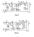
- two terminals 1 and 2 for connection to the telephone line are connected by two resistors 3 and 4 with positive temperature coefficient (PTC) to a resistance 5 with voltage coefficient (VDR), these three resistors being thermally coupled .
- the common studs of a double combined switch 6 (hook) are connected to the common point of the resistors 3 and 5, one directly and the other via a ringing capacitor 7 cooperating with a ringing circuit 8 disposed between the working stud in question of the hook 6 and the point common to the resistors 4 and 5.
- the two inputs of a diode bridge 9, 10, 11, 12 are connected, one, to the other stud of the hook 6 and the other, at the common point of the resistors 4 and 5.
- a transmission and numbering circuit 16 one input of which comprises, in series, a dipole electronic circuit 18 having the role of second protection device, limiter power, as well as a dialing switch 15.
- the circuit 16 is, moreover, provided with a dialing input connected to a keypad 17, and a periodic interrupt control output connected to the switch 15.
- the operation of the subscriber station in FIG. 1 is as follows: in the idle state, the hook 6 is in the position shown in the diagram , which allows an alternating ring signal applied to terminals 1 and 2 to activate the circuit 8 via the capacitor 7; when the subscriber picks up, the ringing circuit is interrupted and the line is connected to circuit 16 via the dipole circuit 18 and the switch 15 in the "closed" position; communication is established.
- the subscriber after off-hook, dials the number of his correspondent on the keyboard 17, which, after processing by circuit 16, sends control pulses to switch 15 in order to carry out the periodic line current cuts which will be decoded by the central office.
- the value of the cold resistance of PTC 3 and 4 is sufficient low to be considered almost negligible compared to the total impedance of the subscriber unit.
- the value of the voltage threshold of the resistor VDR 5 is obviously chosen to be greater than the alternating peak activation voltage of the buzzer 8 which is of the order of 80 volts; under these conditions, if an accidental overvoltage occurs on the line connected to terminals 1 and 2, the VDR 5 greatly decreases in value and a current then flows in the PTCs 3 and 4.
- the value of the overvoltage is limited to approximately 200 volts by the VDR 5 while the voltage nominal supply of circuit 16 is of the order of ten volts; it follows that a prolonged overvoltage in the "off-hook” position risks causing the destruction of the circuit 16 by overcurrent at the Zener diodes fixing the internal operating voltages of the said circuit.
- the dipole limiter circuit 18 behaves like a pure resistance of low value with respect to the current consumed by the circuit 16 in normal operation; from a certain current value linked to the presence of an overvoltage, it does not increase any more while the voltage between terminals 19 and 20 continues to increase until a certain value where the current suddenly becomes almost zero ; at this time, the circuit 18 behaves practically like a switch in the open state, the voltage at the terminals 19 and 20 is, in any case, limited by the upstream VDR 5. As soon as the overvoltage disappears, the circuit 18 finds again instantly its previous characteristics.
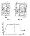
- a limiter / switch circuit 180 is interposed between terminal 19 and a line input terminal 200 of circuit 16, said circuit 180 comprising a control terminal 21 interruption.
- the circuit 180 combines the functions of the switch 15 and of the limiter circuit 18 of FIG. 1; it behaves in normal operation as a transmitter of numbering pulses supplied by the circuit 16 when the keyboard 17 is actuated by the subscriber and, in the presence of an overvoltage, it assumes the power limitation function in the manner previously described.
- the limiter circuit 18 comprises a first transistor 22, of NPN type, the collector of which is connected to the cathode of a diode 23, the anode of the latter. being connected to the input terminal 19; the emitter of transistor 22 is joined to the output terminal 20 by a resistor 24.
- a second and a third transistors 25 and 26, respectively of PNP and NPN types, are arranged in series between the terminals 19 and 20, the transmitters being respectively connected to the latter.
- the bases of transistors 25 and 26 are respectively connected, the first to the collector of transistor 22, and the second to the emitter of the same transistor.
- a fourth transistor 27, of NPN type has its emitter directly connected to terminal 20, while its collector is connected to terminal 19 by means of two resistors 28 and 29 in series.
- the combined collectors of the three transistors 25, 26 and 27 are connected, on the one hand to the base of the transistor 22, and on the other hand to the anode of a diode 30 whose cathode is connected to the collector of the transistor 22.
- the base of the transistor 27 is connected, on the one hand to the terminal 20 by a resistor 31, and on the other hand to the anode of a Zener diode 32 whose cathode is joined to the common point of the resistors 28 and 29.
- the circuit 19 operates in the following manner: on power-up, the base of the transistor 22 is supplied through the resistors 28 and 29, and the collector current of the transistor 22 flows in the diode 23 of the mirror. current constituted by said diode and transistor 25; the collector current of transistor 25 supplying the base of transistor 22, the assembly stabilizes in a conductive state close to complete saturation.
- the diode 30, derives part of the base current of the transistor 22, which makes it possible to possibly reduce the reblocking time of the circuit.
- the transistor 26 begins to flow and the collector current of the transistor 25 is then divided between the base of the transistor 22 and the collector of the transistor 26; the flow rate of transistor 22 stabilizes and the voltage between terminals 19 and 20 increases.
- the collector current of transistor 26 is in a ratio imposed by the current mirror 23, 25, with the collector current of transistor 22, it is ultimately all of these currents which is stabilized.
- Figure 4 illustrates the three operating phases of the circuit of Figure 1.
- the variation in current is linear, the slope of this variation being practically determined by the value of the resistor 24.
- the current stops increasing and is limited to approximately 60 mA.
- the current suddenly drops and remains limited to a very low value determined mainly by the saturation current of the transistor 27 limited by the resistors 28 and 29 in series.
- the protection is thus total since the current flowing between the terminals 19 and 20 is practically interrupted at the moment when the power dissipated in the circuit would risk in the long run leading to the destruction of the latter.
- the combined limiter / switch circuit 180 comprises the same components arranged in the same way as the circuit 18 in FIG. 3, to which a control transistor 33, of PNP type, the collector of which is directly connected to the output terminal 200 and the emitter of which is, moreover, connected to the base of the transistor 22 and to the collectors together of the transistors 25, 26 and 27.
- the base of the transistor 33 is connected, on the one hand to the interrupt control terminal 21, and on the other hand to the cathode of a diode 34 whose anode is joined to the emitter.
- the transistor 33 When the terminal 21 is at a potential slightly higher than that of the output terminal 200, the transistor 33 is blocked and the limiter circuit operates in the same way as the circuit 18 in FIG. 3. If the control terminal 21 is worn at a negative voltage with respect to terminal 200, the transistor 33 is brought to saturation, which has the effect of blocking the transistor 22, and therefore interrupting the current flowing between the terminals 19 and 200; it is therefore sufficient to apply to terminal 21 pulses of negative voltage compatible in duration, number and rhythm with the standardized dialing signals to obtain communication with a correspondent.
Landscapes
- Engineering & Computer Science (AREA)
- Signal Processing (AREA)
- Power Engineering (AREA)
- Devices For Supply Of Signal Current (AREA)
- Interface Circuits In Exchanges (AREA)
- Emergency Protection Circuit Devices (AREA)
Claims (3)
Applications Claiming Priority (2)
| Application Number | Priority Date | Filing Date | Title |
|---|---|---|---|
| FR8107673A FR2504323B1 (fr) | 1981-04-16 | 1981-04-16 | Poste telephonique d'abonne muni d'un dispositif de protection contre les surtensions |
| FR8107673 | 1981-04-16 |
Publications (2)
| Publication Number | Publication Date |
|---|---|
| EP0077360A1 EP0077360A1 (de) | 1983-04-27 |
| EP0077360B1 true EP0077360B1 (de) | 1985-12-18 |
Family
ID=9257486
Family Applications (1)
| Application Number | Title | Priority Date | Filing Date |
|---|---|---|---|
| EP82901310A Expired EP0077360B1 (de) | 1981-04-16 | 1982-04-16 | Mit überspannungsschutzeinrichtungen versehener teilnehmerfernsprechapparat |
Country Status (8)
| Country | Link |
|---|---|
| US (1) | US4475012A (de) |
| EP (1) | EP0077360B1 (de) |
| JP (1) | JPS58500546A (de) |
| AU (1) | AU544171B2 (de) |
| BR (1) | BR8207583A (de) |
| DE (1) | DE3267986D1 (de) |
| FR (1) | FR2504323B1 (de) |
| WO (1) | WO1982003733A1 (de) |
Families Citing this family (31)
| Publication number | Priority date | Publication date | Assignee | Title |
|---|---|---|---|---|
| BE897772A (fr) * | 1983-09-19 | 1984-03-19 | Itt Ind Belgium | Contacts electroniques et dispositifs associes |
| FR2552604B1 (fr) * | 1983-09-27 | 1989-02-24 | Europ Composants Electron | Circuit de protection telephonique contre les perturbations electriques |
| FR2558024B1 (fr) * | 1984-01-11 | 1986-05-16 | Horlogerie Photograph Fse | Clavier de numerotation telephonique protege contre les surcharges |
| US5148005A (en) * | 1984-07-10 | 1992-09-15 | Raychem Corporation | Composite circuit protection devices |
| US5064997A (en) * | 1984-07-10 | 1991-11-12 | Raychem Corporation | Composite circuit protection devices |
| US5089688A (en) * | 1984-07-10 | 1992-02-18 | Raychem Corporation | Composite circuit protection devices |
| US4630162A (en) * | 1984-07-31 | 1986-12-16 | Texas Instruments Incorporated | ESD input protection circuit |
| US4644437A (en) * | 1985-11-01 | 1987-02-17 | At&T Bell Laboratories | Telephone subscriber loop overvoltage protection integrated circuit |
| US4757528A (en) * | 1986-09-05 | 1988-07-12 | Harris Corporation | Thermally coupled information transmission across electrical isolation boundaries |
| FR2606929B1 (fr) * | 1986-11-14 | 1989-02-10 | Telemecanique Electrique | Dispositif interrupteur pour appareil de protection |
| FR2606946A1 (fr) * | 1986-11-17 | 1988-05-20 | Telephonie Ind Commerciale | Dispositif de protection d'un equipement terminal chez un abonne telephonique |
| US4794640A (en) * | 1987-02-24 | 1988-12-27 | Inventa Electronics Co., Ltd. | Switching control apparatus for intercom-telephone sets |
| FR2616277B1 (fr) * | 1987-06-05 | 1990-12-07 | Thomson Semiconducteurs | Circuit pour poste telephonique incorporant une protection contre les surcharges de tension |
| EP0353166A3 (de) * | 1988-07-25 | 1991-04-10 | John Fluke Mfg. Co., Inc. | Überspannungsschutzschaltung |
| JPH02168815A (ja) * | 1988-10-17 | 1990-06-28 | Gte Prod Corp | ソリッドステートステーション保護装置 |
| US5077630A (en) * | 1990-03-28 | 1991-12-31 | Delta Design And Development Co. | Integrated services digital network terminating resistor with line fault protector |
| US5337208A (en) * | 1991-12-18 | 1994-08-09 | Nec America, Inc. | In-line AC current limiter |
| IT1254796B (it) * | 1992-02-17 | 1995-10-11 | St Microelectronics Srl | Dispositivo di limitazione della tensione operativa per interruttori meccanici in telefonia. |
| JP3360184B2 (ja) * | 1993-09-20 | 2002-12-24 | 富士通株式会社 | 光加入者伝送システムに於ける給電制御方式 |
| FR2719721B1 (fr) * | 1994-05-09 | 1996-09-20 | Sgs Thomson Microelectronics | Protection d'interface de lignes téléphoniques. |
| US6331763B1 (en) * | 1998-04-15 | 2001-12-18 | Tyco Electronics Corporation | Devices and methods for protection of rechargeable elements |
| US6870722B2 (en) * | 1999-06-24 | 2005-03-22 | Relcom, Inc. | Enhanced spur cable circuit protection device and method for its implementation |
| US6366437B1 (en) * | 1999-06-24 | 2002-04-02 | Relcom, Inc. | Current limiter for a network |
| US6266223B1 (en) | 1999-06-30 | 2001-07-24 | Tyco Electronics Corporation | Line protector for a communications circuit |
| US20070025549A1 (en) * | 2005-07-06 | 2007-02-01 | Yoshinobu Fujiwara | Telephone interface circuit |
| TWI293220B (en) * | 2005-11-07 | 2008-02-01 | Benq Corp | Circuit for charging protection |
| US7822195B2 (en) * | 2006-07-06 | 2010-10-26 | Uniden Corporation | Telephone interface circuit |
| US7940922B2 (en) * | 2006-07-06 | 2011-05-10 | Uniden Corporation | Telephone interface circuit |
| US7995744B2 (en) * | 2007-01-31 | 2011-08-09 | Uniden Corporation | Telephone interface circuit |
| US20080285741A1 (en) * | 2007-05-16 | 2008-11-20 | Uniden Corporation | Telephone interface circuit |
| US8411848B2 (en) * | 2008-11-11 | 2013-04-02 | Uniden Corporation | Telephone interface circuit for providing over-current and over-voltage protection |
Family Cites Families (7)
| Publication number | Priority date | Publication date | Assignee | Title |
|---|---|---|---|---|
| US3558830A (en) * | 1969-04-09 | 1971-01-26 | Communication Technology Inc | Overvoltage transmission line protector |
| US3925624A (en) * | 1974-12-27 | 1975-12-09 | Bell Telephone Labor Inc | Coupling circuit for providing bilateral protection from hazardous voltages |
| DE2614019C3 (de) * | 1976-04-01 | 1978-09-21 | Hagenuk Vormals Neufeldt & Kuhnke Gmbh, 2300 Kiel | Schaltungsanordnung zur Erzeugung definierter Ausgangspotentiale in Einrichtungen zum tastenbetätigten Verbindungsaufbau in Fernmelde-, insbesondere Fernsprechanlagen |
| US4068281A (en) * | 1976-09-15 | 1978-01-10 | General Electric Company | Thermally responsive metal oxide varistor transient suppression circuit |
| US4099216A (en) * | 1976-11-12 | 1978-07-04 | Westinghouse Electric Corp. | Fuseless intrinsic safety barrier |
| DE2742623A1 (de) * | 1977-09-22 | 1979-04-05 | Deutsche Fernsprecher Gmbh | Tastenwahlschaltungsanordnung zur impulswahl bei fernsprechanlagen |
| US4314196A (en) * | 1980-07-14 | 1982-02-02 | Motorola Inc. | Current limiting circuit |
-
1981
- 1981-04-16 FR FR8107673A patent/FR2504323B1/fr not_active Expired
-
1982
- 1982-04-16 WO PCT/NL1982/000011 patent/WO1982003733A1/en active IP Right Grant
- 1982-04-16 AU AU83391/82A patent/AU544171B2/en not_active Ceased
- 1982-04-16 BR BR8207583A patent/BR8207583A/pt unknown
- 1982-04-16 US US06/403,590 patent/US4475012A/en not_active Expired - Fee Related
- 1982-04-16 DE DE8282901310T patent/DE3267986D1/de not_active Expired
- 1982-04-16 EP EP82901310A patent/EP0077360B1/de not_active Expired
- 1982-04-16 JP JP57501375A patent/JPS58500546A/ja active Pending
Also Published As
| Publication number | Publication date |
|---|---|
| AU8339182A (en) | 1982-11-04 |
| EP0077360A1 (de) | 1983-04-27 |
| BR8207583A (pt) | 1983-03-29 |
| AU544171B2 (en) | 1985-05-16 |
| WO1982003733A1 (en) | 1982-10-28 |
| JPS58500546A (ja) | 1983-04-07 |
| DE3267986D1 (en) | 1986-01-30 |
| FR2504323B1 (fr) | 1985-10-31 |
| US4475012A (en) | 1984-10-02 |
| FR2504323A1 (fr) | 1982-10-22 |
Similar Documents
| Publication | Publication Date | Title |
|---|---|---|
| EP0077360B1 (de) | Mit überspannungsschutzeinrichtungen versehener teilnehmerfernsprechapparat | |
| EP0687051B1 (de) | Telefonleitungs-Interface-Schutz | |
| CA1285020C (fr) | Alimentation en energie electrique continue secourue avec une signalisation de l'etat de secours par inversion de polarite | |
| FR2498389A1 (fr) | Protection d'un circuit de ligne contre les surtensions | |
| FR2521791A1 (fr) | Interrupteur electronique de courant monte dans un systeme de distribution de courant continu | |
| FR2619262A1 (fr) | Dispositif de protection d'un equipement contre les surtensions induites sur une ligne lui etant raccordee | |
| EP0798910B1 (de) | Überspannungsschutz für eine Fernsprechleitungsschnittstelle | |
| EP0026138A1 (de) | Elektronische Vorrichtung zum Steuern der Zündspule einer Brennkraftmaschine und Brennkraftmaschine mit einer solchen Vorrichtung | |
| EP0150524B1 (de) | Anordnung für eine zeitlich definierte Leitungsunterbrechung durch eine Fernsprechteilnehmerstelle | |
| EP0677907A1 (de) | Überstromschutzvorrichtung | |
| EP0294303B1 (de) | Schaltung für eine Telefonstation, die einen Schutz gegen Spannungsüberlastung enthält | |
| FR2499325A1 (fr) | Circuit de protection pour dispositifs a circuits integres | |
| CA1192324A (fr) | Poste telephonique d'abonne muni de dispositifs de protection contre les surtensions | |
| EP0619637B1 (de) | Schutz eines Kraftfahrzeugdrehstromgenerators | |
| FR2549309A1 (fr) | Dispositif de protection contre les surtensions a usage domestique ou industriel | |
| EP0127517A1 (de) | Verbindungssatz für Amtsleitungseinheit | |
| BE898489A (fr) | Circuit de suppression de sensiblité de microphone d'un poste d'abonné téléphonique. | |
| EP1111750B1 (de) | Schutzvorrichtung gegen elektrische Fehler | |
| BE898305A (fr) | Circuit électronique de maintien perfectionné. | |
| EP0404692B1 (de) | Schutzanordnung für eine Spannungsquelle gegen Kurzschlüsse | |
| FR2904497A1 (fr) | Protection d'une ligne de communication | |
| EP0739073B1 (de) | Differentialschutz | |
| BE902286R (fr) | Contacts electroniques et dispositifs associes. | |
| EP0148808B1 (de) | Gegen Überlastung geschützte Fernsprechwähltastatur | |
| BE898306A (fr) | Circuit électronique de libération de maintien perfectionné. |
Legal Events
| Date | Code | Title | Description |
|---|---|---|---|
| PUAI | Public reference made under article 153(3) epc to a published international application that has entered the european phase |
Free format text: ORIGINAL CODE: 0009012 |
|
| 17P | Request for examination filed |
Effective date: 19820909 |
|
| AK | Designated contracting states |
Designated state(s): BE CH DE FR GB LI SE |
|
| GRAA | (expected) grant |
Free format text: ORIGINAL CODE: 0009210 |
|
| AK | Designated contracting states |
Designated state(s): BE CH DE FR GB LI SE |
|
| REF | Corresponds to: |
Ref document number: 3267986 Country of ref document: DE Date of ref document: 19860130 |
|
| PG25 | Lapsed in a contracting state [announced via postgrant information from national office to epo] |
Ref country code: SE Effective date: 19860131 |
|
| PG25 | Lapsed in a contracting state [announced via postgrant information from national office to epo] |
Ref country code: LI Effective date: 19860430 Ref country code: CH Effective date: 19860430 Ref country code: BE Effective date: 19860430 |
|
| PLBE | No opposition filed within time limit |
Free format text: ORIGINAL CODE: 0009261 |
|
| STAA | Information on the status of an ep patent application or granted ep patent |
Free format text: STATUS: NO OPPOSITION FILED WITHIN TIME LIMIT |
|
| BERE | Be: lapsed |
Owner name: N.V. PHILIPS' GLOEILAMPENFABRIEKEN Effective date: 19860430 |
|
| 26N | No opposition filed | ||
| REG | Reference to a national code |
Ref country code: CH Ref legal event code: PL |
|
| PG25 | Lapsed in a contracting state [announced via postgrant information from national office to epo] |
Ref country code: FR Free format text: LAPSE BECAUSE OF NON-PAYMENT OF DUE FEES Effective date: 19871230 |
|
| GBPC | Gb: european patent ceased through non-payment of renewal fee | ||
| PG25 | Lapsed in a contracting state [announced via postgrant information from national office to epo] |
Ref country code: DE Effective date: 19880101 |
|
| REG | Reference to a national code |
Ref country code: FR Ref legal event code: ST |
|
| PG25 | Lapsed in a contracting state [announced via postgrant information from national office to epo] |
Ref country code: GB Effective date: 19881121 |