EP0077303A2 - Dispositif pour rompre au moins une tige continue dans une machine de fabrication de produits pour fumeurs - Google Patents
Dispositif pour rompre au moins une tige continue dans une machine de fabrication de produits pour fumeurs Download PDFInfo
- Publication number
- EP0077303A2 EP0077303A2 EP82830204A EP82830204A EP0077303A2 EP 0077303 A2 EP0077303 A2 EP 0077303A2 EP 82830204 A EP82830204 A EP 82830204A EP 82830204 A EP82830204 A EP 82830204A EP 0077303 A2 EP0077303 A2 EP 0077303A2
- Authority
- EP
- European Patent Office
- Prior art keywords
- rod
- separating element
- shaft
- breaking
- extremity
- Prior art date
- Legal status (The legal status is an assumption and is not a legal conclusion. Google has not performed a legal analysis and makes no representation as to the accuracy of the status listed.)
- Granted
Links
Images
Classifications
-
- A—HUMAN NECESSITIES
- A24—TOBACCO; CIGARS; CIGARETTES; SIMULATED SMOKING DEVICES; SMOKERS' REQUISITES
- A24C—MACHINES FOR MAKING CIGARS OR CIGARETTES
- A24C5/00—Making cigarettes; Making tipping materials for, or attaching filters or mouthpieces to, cigars or cigarettes
- A24C5/14—Machines of the continuous-rod type
- A24C5/31—Machines of the continuous-rod type with special arrangements coming into operation during starting, slowing-down or breakdown of the machine, e.g. for diverting or breaking the continuous rod
-
- Y—GENERAL TAGGING OF NEW TECHNOLOGICAL DEVELOPMENTS; GENERAL TAGGING OF CROSS-SECTIONAL TECHNOLOGIES SPANNING OVER SEVERAL SECTIONS OF THE IPC; TECHNICAL SUBJECTS COVERED BY FORMER USPC CROSS-REFERENCE ART COLLECTIONS [XRACs] AND DIGESTS
- Y10—TECHNICAL SUBJECTS COVERED BY FORMER USPC
- Y10T—TECHNICAL SUBJECTS COVERED BY FORMER US CLASSIFICATION
- Y10T225/00—Severing by tearing or breaking
- Y10T225/10—Methods
- Y10T225/16—Transversely of continuously fed work
-
- Y—GENERAL TAGGING OF NEW TECHNOLOGICAL DEVELOPMENTS; GENERAL TAGGING OF CROSS-SECTIONAL TECHNOLOGIES SPANNING OVER SEVERAL SECTIONS OF THE IPC; TECHNICAL SUBJECTS COVERED BY FORMER USPC CROSS-REFERENCE ART COLLECTIONS [XRACs] AND DIGESTS
- Y10—TECHNICAL SUBJECTS COVERED BY FORMER USPC
- Y10T—TECHNICAL SUBJECTS COVERED BY FORMER US CLASSIFICATION
- Y10T225/00—Severing by tearing or breaking
- Y10T225/30—Breaking or tearing apparatus
- Y10T225/336—Conveyor diverter for moving work
-
- Y—GENERAL TAGGING OF NEW TECHNOLOGICAL DEVELOPMENTS; GENERAL TAGGING OF CROSS-SECTIONAL TECHNOLOGIES SPANNING OVER SEVERAL SECTIONS OF THE IPC; TECHNICAL SUBJECTS COVERED BY FORMER USPC CROSS-REFERENCE ART COLLECTIONS [XRACs] AND DIGESTS
- Y10—TECHNICAL SUBJECTS COVERED BY FORMER USPC
- Y10T—TECHNICAL SUBJECTS COVERED BY FORMER US CLASSIFICATION
- Y10T225/00—Severing by tearing or breaking
- Y10T225/30—Breaking or tearing apparatus
- Y10T225/371—Movable breaking tool
Definitions
- one or more continuous cigarette or filter rods are formed by enclosing tobacco or filtering material in paper webs that are supplied in an uninterrupted sequence and on which one edge is pre-provided with adhesive.
- the said rods are subsequently divided into small lengths of cigarettes or filters.
- the rod of tobacco projecting from the cigarette making machine is made to deviate from the rectilineal path that would have taken it to the cutting device and is sent, instead, towards a collection bin.
- action may be required on the part of an element with which to break the rod of tobacco, due to emergency conditions having arisen (for example, there could be choking downstream of the cutting device).
- the said device comprises deviation means constituted by a movable arcuate deflector that is able to re-route, when placed in a given position, the rod from the rectilineal path towards a collection bin.
- the separating element described in the said patent is constituted by the said arcuate deflector itself which, upon completion of the start-up stage, is displaced from the position of deviation to a position external to the path followed by the rod, passing across the latter.
- One problem with the device as described is that there are limitations in the operating speed of the separating element due to this being powered by electromagnetic operating means.
- the operating speed of the separating element is increased, in British Patent No. 1,280,981, because of the said electromagnetic means being replaced by a spring.
- the object of the invention is to construct a breaking device able to overcome all the difficulties encountered with the known art, that is to say, a fully automatic breaking device that is given a very high operating speed and is in a position to function at any time, both when the machine is being started and under any emergency con- diticn.
- the device for breaking at least one continuous rod in a machine for making products for smokers comprising a separating element movable across the path of the said rod from a first to a second position, characterized by the fact that it comprises operating means of an elastic type for displacing the said separating element alternately from the said first to the said second position, and from the said second to the said first position, automatic means for loading the said operating means of an elastic type, means for restraining the said separating element in positions corresponding to the said first and the said second position, and means for controlling the said means of restraint.
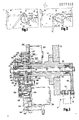
- FIG. 1 shown globally at 1 there is a conveyor belt that moves horizontally and is supported by a vertical wall 2 belonging to the casing of a non-illustrated cigarette making machine.
- the said conveyor 1 is provided with a belt 3 mounted endlessly around rollers 4 (one only of which is visible in the figures), the axes of these being perpendicular to the wall 2.
- the conveyor belt 1 supplies a rod of tobacco 5 coming from non-illustrated forming apparatus, to a verification device 6.
- the said breaking device 7 comprises (see Figures 1 and 2) an arcuate deflector 8 mounted, through a pin 9, on one extremity of a rod 10 that is pivoted to one extremity of a shaft 11 perpendicular to the wall 2 (see also Figure 3).
- a loosely turning roller 12 is also mounted on the said pin 9, in a hollow space in the deflector 8.
- the rod 10, the arcuate deflector 8 and the loosely turning roller 12 jointly define an element 13 for separating the rod of tobacco 5.
- the aforementioned shaft 11 is mounted, with the interposition of two bearings 14, inside a sleeve 15 which, in the region of a hole 16, passes through the wall 2 and is secured to this via a flange 17.
- the other extremity of the shaft 11 projects from the sleeve 15 and supports, from right to left when looking at Figure 3, a first and a second two-arm lever shown at 18 and 19, respectively.
- the two-arm lever 18 is keyed to the shaft 11 and, on the side turned towards the lever 19, is provided with a tubular element 20 coaxial to the shaft 11, while the two-arm lever 19 is supported in a rotatable fashion by the said shaft 11 via two bearings 21.
- a plate 22 parallel to the wall 2.
- the said plate 22 supports, in the space in between it and the said wall 2, a rotating electromagnet 23 and an electric motor 24, the former situated above and latter situated below the sleeve 15 (see Figure 3).
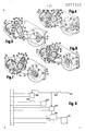
- the said roller 30 which, in combination with the bar 29, defines the means for restraining the breaking device 7 can, as shown in Figures 4 to 7, be engaged in one or the other of the two recesses 32 and 33 with which the opposite edges of the extremity of one arm 34 of the two-arm lever 18 are provided.
- the extremity of the other arm 35 of the two-arm lever 18 has passing through it, a pin 36 parallel to the shaft 11.
- the said pin 36 supports a roller 37, made preferably of rubber or of some similar resilient material, and this is able to rest, as will be explained better in due course, against one or the other of the two abutment profiles 38 and 39, respectively, (the former on the left and the latter on the right in Figures 4 to 7), with which the upper edge of the plate 22 is provided.
- Machined in the other extreme section of the pin 36 there are two annular slots shown at 40 and 41, respectively, (the former on the right and the latter on the left in Figure 3).
- the said slots 40 and 41 are aligned, each along a plane perpendicular to the shaft 11, with two identical slots 42 and 43, respectively, with which a pin 44 parallel to the pin 36 and supported by the extremity of one arm 45 of the said two-arm lever 19, is provided.
- a helical torsion spring 46 is wound around the previously mentioned tubular element, and the two extremities of the spring, shown at 47 and 48, extend towards the pair of pins 36 and 44.
- the said extremities 47 and 48 are situated on opposite sides with respect to the said pair of pins 36 and 44 and are adjacent to the pair of slots 41 and 43, respectively, and to the pair of slots 40 and 42, respectively, when in the situations as illustrated in Figures 5 and 7, while they engage with the slots 43-40 or 42-41, respectively, during the operating stages shown in Figures 4 and 6.
- the other arm of the said lever 19, shown at 49, is connected, via a pin 50, to one extremity of a link rod 51, the free extremity of which is connected eccentrically, through a pin 52 parallel to the pins 36 and 44, to a disc 53 keyed to the shaft 26.
- the said capacitive sensor 56 is connected to a switch 57 that is placed along the line supplying electricity to the motor 24, and is in an open condition when one of the cutaways 54 or 55 is facing the said sensor 56.
- the electrical circuit for the operation of the described device, illustrated in Figure 8, comprises, furthermore, a timer 58 with an opening lag, the purpose of which is to operate a normally open switch 59 located along the line supplying electricity to the electromagnet 23.
- a second timer 60 with both a closing and an opening lag, operates a normally open switch 61 paralleled with the said switch 57.
- the delay with which the timer 58 is able, from the moment it is energized, to close the switch 59 has been deliberately chosen greater than that with which the timer 60 reopens the switch 61 after having closed it.
- the separating element 13 occupies an upper limit position, hereinafter defined the first position, and it intercepts the rod 5 causing the latter to deviate from its normal path and to go towards a non-illustrated reject bin.
- a lower limit position defined the second position (see Figure 2), is reached by the element 13 following a counterclockwise rotation of this around the shaft 11.
- the rod 5 is subjected to stress whereby it is broken in the region of the upper generatrix of the roller 4, and thus the deviated section that has been separated drops downwards.
- the new leading end of the rod 5 is directed towards the verification device 6 with the rectilineal path being resumed.
- the two-arm lever 19 is, instead, kept in a condition of maximum counterclockwise rotation around the shaft 11, by the link rod 51, and through the pin 44 coacting with the pin 36 of the two-arm lever 18, it maintains the spring 46 loaded.
- the displacement of the separating element 13 from the second to the first position occurs each time the cigarette making machine comes to a halt, the purpose of this being to eliminate, once operation is resumed, the leading section of the rod of tobacco 5.
- the said displacement can also take place at any moment whilst the cigarette making machine is running, due to emergency conditions having arisen, in order to interrupt the supply of the rod 5 to the cutting device.
- the said displacement from the said second to the said first position takes place with the closing, through manual tripping or upon the operation of non illustrated control devices, of the switch 63.
- the said timer 58 then causes the switch 59 to reopen, and the bar 29 returns to its former position carrying the roller 30 in engagement with the recess 32.
- the timer 60 determines the closing of the switch 61 and the starting of the motor 24 which, through the disc 53 and the link rod 51, causes the two-arm lever 19 to rotate clockwise around the shaft 11.
- the cutaway 55 moves away from the capacitive sensor 56 causing the switch 57 to close, and this is followed by the reopening of the switch 61 on the part of the timer 60.
- the two-arm lever 19 rotates clockwise around the shaft 11 and loads, through the described combined action of the pins 36 and 44, the spring 46 in such a way that the lever 18 be subjected to torque in a clockwise direction, contrasted by the roller 30 engaged in the recess 32.
- the cutaway 54 arrives at the sensor 56 and causes the switch 57 to open and, consequently, the motor 24 to halt.
- the mechanism of the device is able to adopt, upon the switch 59 closing and in accordance with a similar procedure to that seen for the deflector 8 to pass from the second to the first position, the disposition depicted in Figure 7, that is to say, to determine the tripping of the lever 18 whereby the deflector 8 connected thereto be returned to the position as per Figure 2.
- the device according to the invention by overcoming the described difficulties experienced with the devices of a known type, makes it possible to modify, at any moment and with extreme rapidity, the path followed by a rod of tobacco or filter in a cigarette making machine.
- the device in question can, in fact, be gainfully used, for example, with the deflector 8 suitably dimensioned and shaped to alter the path followed by a number of side by side rods of tobacco or filter formed contemporaneously by a cigarette making machine.
Landscapes
- Manufacturing Of Cigar And Cigarette Tobacco (AREA)
- Wire Processing (AREA)
Applications Claiming Priority (2)
| Application Number | Priority Date | Filing Date | Title |
|---|---|---|---|
| IT4945481 | 1981-10-08 | ||
| IT49454/81A IT1171577B (it) | 1981-10-08 | 1981-10-08 | Dispositivo troncatore di almeno un cordone continuo in una macchina confezionatrice di prodotti da fumo |
Publications (3)
| Publication Number | Publication Date |
|---|---|
| EP0077303A2 true EP0077303A2 (fr) | 1983-04-20 |
| EP0077303A3 EP0077303A3 (en) | 1983-08-10 |
| EP0077303B1 EP0077303B1 (fr) | 1985-12-11 |
Family
ID=11270720
Family Applications (1)
| Application Number | Title | Priority Date | Filing Date |
|---|---|---|---|
| EP82830204A Expired EP0077303B1 (fr) | 1981-10-08 | 1982-07-09 | Dispositif pour rompre au moins une tige continue dans une machine de fabrication de produits pour fumeurs |
Country Status (11)
| Country | Link |
|---|---|
| US (1) | US4461415A (fr) |
| EP (1) | EP0077303B1 (fr) |
| JP (1) | JPS5863378A (fr) |
| BR (1) | BR8204379A (fr) |
| CS (1) | CS239931B2 (fr) |
| DD (1) | DD203816A5 (fr) |
| DE (1) | DE3267906D1 (fr) |
| ES (1) | ES8400232A1 (fr) |
| IN (1) | IN157846B (fr) |
| IT (1) | IT1171577B (fr) |
| PL (1) | PL131231B1 (fr) |
Cited By (2)
| Publication number | Priority date | Publication date | Assignee | Title |
|---|---|---|---|---|
| EP1800551A2 (fr) | 2005-12-23 | 2007-06-27 | Hauni Maschinenbau AG | Appareil pour couper un boudin, appareil pour emmener le materiau du boudin, et méthode d'opération d'un appareil de fabrication de tiges dans l'industrie du tabac |
| CN104608175A (zh) * | 2015-02-10 | 2015-05-13 | 广东中烟工业有限责任公司 | 一种气动进刀机构的制造方法 |
Families Citing this family (7)
| Publication number | Priority date | Publication date | Assignee | Title |
|---|---|---|---|---|
| IT1191363B (it) * | 1986-06-25 | 1988-03-16 | Gd Spa | Macchina confezionatrice di sigarette del tipo a baco continuo |
| DE3813786C2 (de) * | 1988-04-23 | 2000-02-17 | Hauni Werke Koerber & Co Kg | Vorrichtung zum Abschneiden eines Stranges der tabakverarbeitenden Industrie |
| JP2578530B2 (ja) * | 1991-04-16 | 1997-02-05 | 峯木 隆良 | 型抜きシートの剥離装置 |
| US5470004A (en) * | 1992-10-14 | 1995-11-28 | Takayoshi Mineki | Separating apparatus for a punched sheet |
| ITBO20010604A1 (it) * | 2001-10-03 | 2003-04-03 | Gd Spa | Unita' di uscita di una macchina confezionatrice di sigarette |
| ITBO20030080A1 (it) * | 2003-02-20 | 2004-08-21 | Gd Spa | Dispositivo e metodo di separazione di almeno un cordone |
| CN106263018B (zh) * | 2015-05-15 | 2018-03-06 | 常德烟草机械有限责任公司 | 一种烟草棒状物的切断装置 |
Citations (1)
| Publication number | Priority date | Publication date | Assignee | Title |
|---|---|---|---|---|
| US4226352A (en) * | 1978-01-13 | 1980-10-07 | Molins Limited | Continuous-rod making machines |
Family Cites Families (2)
| Publication number | Priority date | Publication date | Assignee | Title |
|---|---|---|---|---|
| GB1042148A (en) * | 1962-07-13 | 1966-09-14 | Michael Aren Pym | Improvements in or relating to continuous rod cigarette-making machines |
| GB1280981A (en) * | 1968-07-19 | 1972-07-12 | Molins Machine Co Ltd | Improvements in or relating to continuous rod making machines |
-
1981
- 1981-10-08 IT IT49454/81A patent/IT1171577B/it active
-
1982
- 1982-06-21 IN IN464/DEL/82A patent/IN157846B/en unknown
- 1982-07-09 DE DE8282830204T patent/DE3267906D1/de not_active Expired
- 1982-07-09 EP EP82830204A patent/EP0077303B1/fr not_active Expired
- 1982-07-19 ES ES514138A patent/ES8400232A1/es not_active Expired
- 1982-07-27 BR BR8204379A patent/BR8204379A/pt not_active IP Right Cessation
- 1982-07-27 US US06/402,800 patent/US4461415A/en not_active Expired - Fee Related
- 1982-08-19 JP JP57142734A patent/JPS5863378A/ja active Granted
- 1982-09-16 CS CS826662A patent/CS239931B2/cs unknown
- 1982-10-01 DD DD82243733A patent/DD203816A5/de unknown
- 1982-10-08 PL PL1982238569A patent/PL131231B1/pl unknown
Patent Citations (1)
| Publication number | Priority date | Publication date | Assignee | Title |
|---|---|---|---|---|
| US4226352A (en) * | 1978-01-13 | 1980-10-07 | Molins Limited | Continuous-rod making machines |
Cited By (3)
| Publication number | Priority date | Publication date | Assignee | Title |
|---|---|---|---|---|
| EP1800551A2 (fr) | 2005-12-23 | 2007-06-27 | Hauni Maschinenbau AG | Appareil pour couper un boudin, appareil pour emmener le materiau du boudin, et méthode d'opération d'un appareil de fabrication de tiges dans l'industrie du tabac |
| CN104608175A (zh) * | 2015-02-10 | 2015-05-13 | 广东中烟工业有限责任公司 | 一种气动进刀机构的制造方法 |
| CN104608175B (zh) * | 2015-02-10 | 2017-01-11 | 广东中烟工业有限责任公司 | 一种气动进刀机构的制造方法 |
Also Published As
| Publication number | Publication date |
|---|---|
| ES514138A0 (es) | 1983-10-16 |
| DE3267906D1 (en) | 1986-01-23 |
| US4461415A (en) | 1984-07-24 |
| DD203816A5 (de) | 1983-11-09 |
| BR8204379A (pt) | 1983-07-19 |
| ES8400232A1 (es) | 1983-10-16 |
| EP0077303A3 (en) | 1983-08-10 |
| IT1171577B (it) | 1987-06-10 |
| IT8149454A0 (it) | 1981-10-08 |
| IN157846B (fr) | 1986-07-05 |
| EP0077303B1 (fr) | 1985-12-11 |
| PL131231B1 (en) | 1984-10-31 |
| PL238569A1 (en) | 1983-04-11 |
| JPS5863378A (ja) | 1983-04-15 |
| CS239931B2 (en) | 1986-01-16 |
| JPH0467950B2 (fr) | 1992-10-29 |
Similar Documents
| Publication | Publication Date | Title |
|---|---|---|
| US4461415A (en) | Device for breaking at least one continuous rod in a machine for making products for smokers | |
| US3089661A (en) | Automatic cigarette paper splicer | |
| US2433685A (en) | Apparatus for separating defective sheets as sheared from continuous strip | |
| EP1815757B1 (fr) | Dispositif de découpe pour produits du tabac | |
| EP0327856A1 (fr) | Enrouleur, en particulier pour la production de croissants | |
| US4143664A (en) | Corn cutter jam clearing system | |
| US2618047A (en) | Length control apparatus | |
| US2020877A (en) | Operator for intermittent reciprocating action | |
| GB2078495A (en) | Bread slicing machine | |
| CA1188214A (fr) | Appareil servant a couper et a transporter des feuilles de papier et autres articles du genre | |
| US4928713A (en) | Cigarette making machines | |
| JPH1118702A (ja) | 米飯圧縮成形移送装置 | |
| US4548594A (en) | Method and apparatus for severing sheets of material | |
| US4531436A (en) | Slicing machine having interrupt means | |
| US1623629A (en) | Fur-weighing machine | |
| US2698659A (en) | Sheet tearing table | |
| US3450258A (en) | Device for selectively extracting objects from a continuous stream of objects and especially cigarettes | |
| US4193410A (en) | Apparatus for making ventilated cigarettes | |
| US2272702A (en) | Cutting machine | |
| EP0679744A1 (fr) | Dispositif coupe-trame pour métiers à tisser | |
| US3537227A (en) | Automatically controlled wrapping machine,particularly for the cigarette field | |
| US3911770A (en) | Machine and method for cutting slugs having a uniform linear dimension | |
| US3943684A (en) | Time delay for interleaving machine | |
| US1512929A (en) | Tobacco-cutting machine | |
| GB1440352A (en) | Automatic sheet cutting apparatus |
Legal Events
| Date | Code | Title | Description |
|---|---|---|---|
| PUAI | Public reference made under article 153(3) epc to a published international application that has entered the european phase |
Free format text: ORIGINAL CODE: 0009012 |
|
| AK | Designated contracting states |
Designated state(s): CH DE FR GB LI |
|
| PUAL | Search report despatched |
Free format text: ORIGINAL CODE: 0009013 |
|
| AK | Designated contracting states |
Designated state(s): CH DE FR GB LI |
|
| 17P | Request for examination filed |
Effective date: 19830831 |
|
| GRAA | (expected) grant |
Free format text: ORIGINAL CODE: 0009210 |
|
| AK | Designated contracting states |
Designated state(s): CH DE FR GB LI |
|
| PG25 | Lapsed in a contracting state [announced via postgrant information from national office to epo] |
Ref country code: LI Effective date: 19851211 Ref country code: CH Effective date: 19851211 |
|
| REF | Corresponds to: |
Ref document number: 3267906 Country of ref document: DE Date of ref document: 19860123 |
|
| ET | Fr: translation filed | ||
| REG | Reference to a national code |
Ref country code: CH Ref legal event code: PL |
|
| PLBE | No opposition filed within time limit |
Free format text: ORIGINAL CODE: 0009261 |
|
| STAA | Information on the status of an ep patent application or granted ep patent |
Free format text: STATUS: NO OPPOSITION FILED WITHIN TIME LIMIT |
|
| 26N | No opposition filed | ||
| PGFP | Annual fee paid to national office [announced via postgrant information from national office to epo] |
Ref country code: FR Payment date: 19930617 Year of fee payment: 12 |
|
| PGFP | Annual fee paid to national office [announced via postgrant information from national office to epo] |
Ref country code: GB Payment date: 19930630 Year of fee payment: 12 |
|
| PGFP | Annual fee paid to national office [announced via postgrant information from national office to epo] |
Ref country code: DE Payment date: 19930716 Year of fee payment: 12 |
|
| PG25 | Lapsed in a contracting state [announced via postgrant information from national office to epo] |
Ref country code: GB Effective date: 19940709 |
|
| GBPC | Gb: european patent ceased through non-payment of renewal fee |
Effective date: 19940709 |
|
| PG25 | Lapsed in a contracting state [announced via postgrant information from national office to epo] |
Ref country code: FR Effective date: 19950331 |
|
| PG25 | Lapsed in a contracting state [announced via postgrant information from national office to epo] |
Ref country code: DE Effective date: 19950401 |
|
| REG | Reference to a national code |
Ref country code: FR Ref legal event code: ST |