EP0076178B1 - Procédé et installation de contrôle en place de carburateurs - Google Patents
Procédé et installation de contrôle en place de carburateurs Download PDFInfo
- Publication number
- EP0076178B1 EP0076178B1 EP82401520A EP82401520A EP0076178B1 EP 0076178 B1 EP0076178 B1 EP 0076178B1 EP 82401520 A EP82401520 A EP 82401520A EP 82401520 A EP82401520 A EP 82401520A EP 0076178 B1 EP0076178 B1 EP 0076178B1
- Authority
- EP
- European Patent Office
- Prior art keywords
- carburetor
- throttle
- downstream
- vacuum
- idling
- Prior art date
- Legal status (The legal status is an assumption and is not a legal conclusion. Google has not performed a legal analysis and makes no representation as to the accuracy of the status listed.)
- Expired
Links
- 238000000034 method Methods 0.000 title claims description 14
- 238000009434 installation Methods 0.000 title description 9
- 238000005259 measurement Methods 0.000 claims description 6
- 238000011144 upstream manufacturing Methods 0.000 claims description 6
- 230000008569 process Effects 0.000 claims description 5
- 230000006698 induction Effects 0.000 claims 7
- 238000006467 substitution reaction Methods 0.000 claims 1
- 238000012360 testing method Methods 0.000 description 5
- 239000000446 fuel Substances 0.000 description 4
- 230000007704 transition Effects 0.000 description 4
- 210000000056 organ Anatomy 0.000 description 3
- 239000012634 fragment Substances 0.000 description 2
- 238000013459 approach Methods 0.000 description 1
- 230000008901 benefit Effects 0.000 description 1
- 238000002485 combustion reaction Methods 0.000 description 1
- 230000007423 decrease Effects 0.000 description 1
- 238000010586 diagram Methods 0.000 description 1
- 238000006073 displacement reaction Methods 0.000 description 1
- 230000000694 effects Effects 0.000 description 1
- 238000011156 evaluation Methods 0.000 description 1
- 238000012423 maintenance Methods 0.000 description 1
- 230000007257 malfunction Effects 0.000 description 1
- 239000000203 mixture Substances 0.000 description 1
- 230000009467 reduction Effects 0.000 description 1
- 230000008439 repair process Effects 0.000 description 1
- 238000005070 sampling Methods 0.000 description 1
- 238000012795 verification Methods 0.000 description 1
- 238000011179 visual inspection Methods 0.000 description 1
Images
Classifications
-
- F—MECHANICAL ENGINEERING; LIGHTING; HEATING; WEAPONS; BLASTING
- F02—COMBUSTION ENGINES; HOT-GAS OR COMBUSTION-PRODUCT ENGINE PLANTS
- F02M—SUPPLYING COMBUSTION ENGINES IN GENERAL WITH COMBUSTIBLE MIXTURES OR CONSTITUENTS THEREOF
- F02M19/00—Details, component parts, or accessories of carburettors, not provided for in, or of interest apart from, the apparatus of groups F02M1/00 - F02M17/00
- F02M19/01—Apparatus for testing, tuning, or synchronising carburettors, e.g. carburettor glow stands
Definitions
- the present invention relates to the control of carburetors intended to supply internal combustion engines, of the type comprising an idling circuit opening into the intake duct of the carburetor by an idling orifice placed downstream of the minimum opening position. of the throttle organ and through a progression orifice. It is known that this progression orifice, produced in the form of a slot or of holes staggered along the intake duct, is intended to ensure correct operation of the engine when the driver opens the throttle member, generally constituted by a butterfly, from its minimum open position.
- the present invention aims to provide a method and a control installation for detecting and evaluating the wear of the moving parts of a carburetor while it is in place on the engine which it supplies and, more generally, of allow an evaluation of the wear in a simple and economic way, and this without requiring to use a vacuum pump or a source of compressed air.
- the invention proposes in particular a method of checking the carburetor, in particular with a view to determining the wear of the axis of the throttle member, comprising an idling circuit opening into the intake duct of the carburetor by an idle orifice placed downstream of the minimum opening position of the throttling member and by a progression orifice, characterized in that: the engine is operated; a calibrated passage section is adjusted at the outlet downstream of the idle circuit so that the vacuum in the idle circuit takes the same standard value as for the carburetor in new condition; the throttle member (5) of the carburetor is adjusted to a position where it defines a determined passage section for which, when the carburetor is new, the edge of the throttle member straddles the orifice progression; and this by measuring the depression at the neck of a venturi placed in the inlet duct or at the inlet thereof and by comparing it to a standard depression, taken from the portion located between two calibrated throttles of a channel connecting the atmosphere downstream of the th
- the method is particularly simple to implement because the new carburetors are adjusted in the factory, before assembly, in such a way that the vacuum which prevails in the idling circuit when the carburetor is new is perfectly known and reproducible, this reproducibility n 'not requiring the use of a test bench of the type commonly known as a "flow bench", the engine itself being used as a source of vacuum and circulation pump.
- the invention also proposes a control installation making it possible to implement the invention in a simple manner, the connection means of which with the carburetor can be grouped in a single hose provided with connection elements and possibly with a measuring venturi. which is attached to the carburetor in place of the air filter.
- the invention proposes, by way of particular means enabling it to be implemented, the addition to the series carburetors of elements such as adjustable air intake downstream of the throttling member and intake depression also downstream of the throttle, which have no reason to be on a carburetor whose verification is only expected using a traditional test bench.
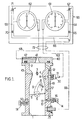
- the inverted carburetor shown in section in FIG. 1 comprises a body made up of several assembled parts delimiting an intake duct 1 provided with an air inlet 2.
- this duct are arranged successively, from upstream to downstream in the direction of air circulation, the outlet of a main spouting system 3, placed at the neck of a venturi 4, and a main throttling member 5 constituted by a butterfly carried by an axis 6 and represented in the open position minimum in FIG. 1.
- the axis 6 crosses the body to allow control of the throttle valve by the driver using a linkage not shown.
- the minimum opening position of the butterfly valve 5 is adjustable by means of an adjustable stop screw 7 in a part 8 secured to the carburetor body. Return springs, not shown, tend to bring the butterfly back to the minimum open position for which a lever 9 secured to the axis 6 comes to bear against the screw 7.
- the carburetor idling and advancement circuit includes a channel 10 supplied with air and fuel.
- the fuel arrives at the channel 10 from a constant level tank (not shown) through a conduit 11.
- the air comes from a source at atmospheric pressure via a calibrated orifice 12.
- the idling circuit opens into the intake duct through an idle orifice whose passage section 13 is adjustable using a wealth screw 14 with conical end 15, braked by a spring 16 which retains it in position.
- the idle channel 10 also communicates with the intake duct 1 through a progression orifice, constituted, in the embodiment described, by a slot 17 placed so as to pass from upstream to downstream of the throttling member 5 when the latter is open from the minimum open position shown in FIG. 1.
- the progression orifice may as well consist of several holes staggered along the duct, in the vicinity of each other.
- the carburetor shown is not provided with an air channel for passing air upstream downstream of the throttle member 5, it is provided with means for directly admitting the atmospheric air downstream of the throttle member 5 and to implement a first embodiment of the invention in a convenient manner. These means make it possible to supply the engine with the air necessary for its operation when, during the implementation of the method, the throttle member 5 occupies its extreme minimum opening position, for which the passage cross section that 'it delimits is less than that necessary to allow the idle air flow to pass.
- the means shown by way of example in FIG. 1 are constituted by a conduit 50, the passage section of which is adjustable using a screw 51. The location where the air intake takes place downstream of the throttling organ is indifferent.
- the duct 50 is not necessary when the intake manifold to the engine has a nozzle allowing, if necessary, to create an adjustable air inlet.
- the carburetor shown in FIG. 1 comprises a hole 73 for taking a vacuum situated downstream from the throttle member 5. During normal operation of the carburetor, this hole 73 is closed by means not shown, such as a threaded pin provided with a seal.
- the actual control installation can be viewed as comprising a panel 60, a connecting hose 72 and members intended to be fixed to the carburetor to be checked.
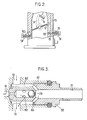
- These latter members include an idle jet 30 provided with a vacuum connection 31, a jet which can moreover be permanently mounted on the carburetor, the vacuum connection being closed for normal operation.
- the nozzle with vacuum connection shown by way of example in FIG. 3 delimits, with the body 81 of the carburetor, an annular chamber 82 which the idle channel crosses through 10. Holes 83 drilled in the nozzle 30 make the chamber 82 communicate with the rear part of the central bore of the nozzle, constituting the vacuum intake duct 31 inside the idle channel 10. The front part of this bore, separated from the rear part by a ball 79 force fitted the fuel through a throttled passage and delivers it into the channel 10 through holes 80.
- These bodies include means for measuring the flow drawn in by the motor.
- these means consist of a shutter plate 40 pierced with a venturi 41 and with a pipe 42 for withdrawing vacuum which opens out at the neck of the venturi.
- a obturator plate 41 makes it possible to achieve much more precision. high, because the venturi drilled in this plate can be of much smaller dimensions than the normal venturi of the carburetor and the flow rates to be measured are very low, since they correspond to an operation of the engine in the vicinity of idling.
- the members added to the carburetor also include a vacuum connection connected to the hole 73 already mentioned.
- Table 60 comprises, in the illustrated embodiment, two differential pressure gauges 61 and 62, the second of which is used for adjusting the flow rate and the first for checking the vacuum.
- the pressure gauges shown are of the pneumatic type and with analog reading. They can be replaced by pressure gauges with sensors, for example of the piezoelectric type, with digital display, for example of the seven-segment type.
- the manometer 61 intended for the measurement of th pressure, has a compartment connected to the vacuum outlet 31 of the idle channel 10 by a link 63.
- the other compartment is connected to the part 64 located between two calibrated orifices 67 and 65, the first of which is adjustable, of a connection 66 connecting an atmospheric pressure supply to the vacuum outlet 73 (the adjustment being effected by section adjustment or by replacement).
- One of the compartments of the pressure gauge 62 is in turn connected to the vacuum sampling duct 42 of the venturi 41, by a connection 68.
- the other compartment of the pressure gauge 62 is connected to the part 69 between two throttles 71 and 70, the first of which is adjustable, of a connection between the atmosphere and the vacuum outlet 73.
- the connections with the vacuum outlet 73 have a common part, downstream of the calibrated orifices 65 and 70.
- connection parts 68, 63 and 66 carried by the switchboard 60 will generally be made up of rigid tubes, while the connection parts can be, over most of their length, grouped in the flexible 72.
- the first step is to put the wealth screw 14 in a position such that the passage section which it delimits is that adopted when adjusting the new carburetor.
- the throttle member 5 is brought into its minimum open position by completely loosening the screw 7.
- the upper edge of the throttle member then comes into a position located downstream of the progression orifice. 17.
- the depression which prevails in the channel 10 practically does not depend on the wear of the member 5 and its axis 6.
- the engine is then operated, opening if necessary the screw 51 by an amount just sufficient to supply the air necessary for idling at a determined speed.
- Port 67 is given the calibration (section Si) previously adopted to adjust the new carburetor.
- the wealth adjustment screw 14 is then turned to bring the pressure gauge 61 to zero.
- the vacuum prevailing in the idle circuit has the "standard" value defined for the new carburetor.
- This result is probably achieved by the fact that, the mixture of air and petrol flowing around the cone 15 of the screw 14 at sonic speed, even for the idling operating vacuum, the value of the vacuum downstream of the throttle member 5 has no influence on the measurement. Any additional air intake, due for example to the wear of the throttle shaft 6, has no influence on the measurement.
- the next step consists in opening the throttling member 5, by tightening the screw 7, until the vacuum generated at the neck of the venturi 41 is equal to a standard vacuum, defined by a suitable passage section and predetermined S. of the calibrated orifice 71.
- This depression corresponds to an upstream flow downstream of the throttle member 5 for which, when the carburetor is new, the edge of the throttle member 5 is straddling the transition orifice 17.
- the screw 51 is closed, the supply of air by the conduit 50 being no longer necessary to allow engine operation.
- the displacement of the edge of the throttle member 5 until it straddles the transition orifice 17 increases the vacuum in the idle channel 10, since the passage section subjected at the vacuum downstream of the carburetor increases and the corresponding pressure drop decreases.
- the orifice 67 is then given the calibration (section S, ' ⁇ Si) which, when the carburetor was new, revealed, in part 64, a depression equal to that which prevailed in channel 10 on this same new carburetor .
- the throttle stop screw 5 must be returned to the position giving the engine an idle speed.
- the calibrated orifice 71 is adjusted to a new predetermined value 5 ' 2 > 5 2 and the throttle valve 5 is adjusted by the screw 7 until the indication of the pressure gauge 62 is brought to zero.
- the air flow passing through the intake duct from upstream to downstream of the throttle valve is then the standard flow required for this adjustment.
- the invention is susceptible of numerous practical embodiments.
- the various calibrated orifices necessary for the calibrations can be preset and mounted on a distributor incorporated in the installation so as to be switchable. This avoids manipulation likely to degrade them.
- the throttle opening positions can be adjusted before the start of a cold engine, by adjusting the air flow rates by means of particular calibrated orifices 71.
- the minimum opening position of a starting flap can be adjusted after starting a cold engine.
- a variant of the method described above overcomes step 1 and the need for a closable air supply (duct 50 and screw 51 in FIG. 1).
- step 2 On the carburetor to be checked, step 2 is immediately approached, which takes place as follows: the throttle member 5 is kept in a partially open position, using for example the screw 7 and the idle orifice is closed by replacing the richness screw 14 with a shutter. Then the throttle member 5 is closed until the air flow which bypasses it is equal to that for which, on the new carburetor, the edge of the member 5 straddles the orifice for progression.
- This adjustment is carried out by bringing the pressure gauge indicator 62 to zero, the calibrated orifice 71 in place having the section S 3 .
- step 3 giving the orifice 67 the calibration (section S 4 ) which reveals, in part 64, a depression equal to that which prevails in the idle channel of a new carburetor: any wear reduces the vacuum in the duct 10, as before, and the imbalance of the pressure gauge makes it possible to assess the degree of wear.
- the adjustment of the stop screw 7 can be carried out as in step 4 previously described.
- This simplified variant makes it possible, on condition of providing a shutter to replace the wealth screw 14 provided with an internal channel, which is connected to the pressure gauge 61, to leave the normal idle jet in place instead of replacing it with a nozzle 30 provided with a vacuum outlet.
Landscapes
- Engineering & Computer Science (AREA)
- Chemical & Material Sciences (AREA)
- Combustion & Propulsion (AREA)
- Mechanical Engineering (AREA)
- General Engineering & Computer Science (AREA)
- Control Of Throttle Valves Provided In The Intake System Or In The Exhaust System (AREA)
- Measuring Arrangements Characterized By The Use Of Fluids (AREA)
- Control Of The Air-Fuel Ratio Of Carburetors (AREA)
Applications Claiming Priority (2)
| Application Number | Priority Date | Filing Date | Title |
|---|---|---|---|
| FR8118484 | 1981-09-30 | ||
| FR8118484A FR2513698A1 (fr) | 1981-09-30 | 1981-09-30 | Procede et installation de controle en place de carburateurs |
Publications (3)
| Publication Number | Publication Date |
|---|---|
| EP0076178A2 EP0076178A2 (fr) | 1983-04-06 |
| EP0076178A3 EP0076178A3 (en) | 1983-12-07 |
| EP0076178B1 true EP0076178B1 (fr) | 1986-12-10 |
Family
ID=9262634
Family Applications (1)
| Application Number | Title | Priority Date | Filing Date |
|---|---|---|---|
| EP82401520A Expired EP0076178B1 (fr) | 1981-09-30 | 1982-08-11 | Procédé et installation de contrôle en place de carburateurs |
Country Status (7)
| Country | Link |
|---|---|
| US (1) | US4483186A (enExample) |
| EP (1) | EP0076178B1 (enExample) |
| JP (1) | JPS5870041A (enExample) |
| DE (1) | DE3274668D1 (enExample) |
| ES (1) | ES515660A0 (enExample) |
| FR (1) | FR2513698A1 (enExample) |
| PT (1) | PT75457B (enExample) |
Cited By (1)
| Publication number | Priority date | Publication date | Assignee | Title |
|---|---|---|---|---|
| RU2484112C2 (ru) * | 2011-07-28 | 2013-06-10 | Ольга Юрьевна Доротюк | Пигментная паста |
Families Citing this family (6)
| Publication number | Priority date | Publication date | Assignee | Title |
|---|---|---|---|---|
| US4974444A (en) * | 1989-07-05 | 1990-12-04 | Ford Motor Company | Electronically controlled engine throttle plate adjustment |
| US5203300A (en) * | 1992-10-28 | 1993-04-20 | Ford Motor Company | Idle speed control system |
| US7228729B1 (en) | 2006-07-26 | 2007-06-12 | Lincoln Industrial Corporation | Apparatus and method for testing fuel flow |
| US7516670B2 (en) * | 2006-10-12 | 2009-04-14 | Schmuck Cory D | Multi-channel manometer with independent fluid level adjustments |
| US7587931B2 (en) * | 2008-01-29 | 2009-09-15 | Lincoln Industrial Corporation | Apparatus and method for testing fuel flow |
| CN111677601B (zh) * | 2020-06-23 | 2022-04-22 | 湛江德利车辆部件有限公司 | 双腔化油器调整装置、双腔化油器调整设备及其调整方法 |
Family Cites Families (7)
| Publication number | Priority date | Publication date | Assignee | Title |
|---|---|---|---|---|
| US2494936A (en) * | 1944-07-08 | 1950-01-17 | Carter Carburetor Corp | Carburetor testing device and method |
| US4050428A (en) * | 1972-09-13 | 1977-09-27 | Nissan Motor Co., Limited | Carburetor intake air flow measuring device |
| DE2327796C3 (de) * | 1973-06-01 | 1978-09-28 | Joachim Dipl.-Ing. 7141 Steinheim Huhnen | Verfahren zum Herstellen von ösen an Schraubenzugfedern |
| JPS5287531A (en) * | 1976-01-19 | 1977-07-21 | Hitachi Ltd | Apparatus for making diagnosis of operation of secondary valve of cabu retor |
| FR2354552A1 (fr) * | 1976-06-10 | 1978-01-06 | Deutsche Vergaser Gmbh Co Kg | Dispositif de verification du fonctionnement de carburateurs installes sur des moteurs a explosion |
| FR2465992A1 (fr) * | 1979-09-21 | 1981-03-27 | Sibe | Dispositif indicateur d'usure d'axe rotatif, notamment pour carburateur |
| US4269062A (en) * | 1979-10-10 | 1981-05-26 | Colt Industries Operating Corp. | Method for gauging fluid flow |
-
1981
- 1981-09-30 FR FR8118484A patent/FR2513698A1/fr active Granted
-
1982
- 1982-08-11 DE DE8282401520T patent/DE3274668D1/de not_active Expired
- 1982-08-11 EP EP82401520A patent/EP0076178B1/fr not_active Expired
- 1982-08-24 PT PT75457A patent/PT75457B/pt not_active IP Right Cessation
- 1982-09-11 ES ES515660A patent/ES515660A0/es active Granted
- 1982-09-20 US US06/420,350 patent/US4483186A/en not_active Expired - Lifetime
- 1982-09-30 JP JP57172481A patent/JPS5870041A/ja active Granted
Cited By (1)
| Publication number | Priority date | Publication date | Assignee | Title |
|---|---|---|---|---|
| RU2484112C2 (ru) * | 2011-07-28 | 2013-06-10 | Ольга Юрьевна Доротюк | Пигментная паста |
Also Published As
| Publication number | Publication date |
|---|---|
| PT75457B (fr) | 1984-10-23 |
| EP0076178A3 (en) | 1983-12-07 |
| FR2513698B1 (enExample) | 1984-01-13 |
| DE3274668D1 (en) | 1987-01-22 |
| FR2513698A1 (fr) | 1983-04-01 |
| ES8305466A1 (es) | 1983-05-01 |
| PT75457A (fr) | 1982-09-01 |
| JPH0341674B2 (enExample) | 1991-06-24 |
| ES515660A0 (es) | 1983-05-01 |
| JPS5870041A (ja) | 1983-04-26 |
| US4483186A (en) | 1984-11-20 |
| EP0076178A2 (fr) | 1983-04-06 |
Similar Documents
| Publication | Publication Date | Title |
|---|---|---|
| WO2023020797A1 (fr) | Capteur de détermination d'un niveau de liquide pour un réservoir d'aéronef, ensemble d'un réservoir et d'un capteur, procédé d'utilisation d'un tel capteur | |
| EP0076178B1 (fr) | Procédé et installation de contrôle en place de carburateurs | |
| EP2058641B1 (fr) | Sonde iso-cinétique pour l'analyse de la pollution des gaz générés par un moteur d'avion | |
| FR2656421A1 (fr) | Machine a fumer. | |
| FR2811020A1 (fr) | Injecteur commande en pression avec une buse d'injection a registre variable | |
| EP0109883A1 (fr) | Installation pour le contrôle de la pression de réglage d'une soupape de sécurité | |
| EP0136946B1 (fr) | Méthode de mesure directe du débit d'air traversant un joint labyrinthe de turbomachine | |
| FR2718506A1 (fr) | Soupape de limitation de pression et procédé de réglage d'une pression d'ouverture de cette soupape. | |
| FR3109405A1 (fr) | Turbomachine équipée d’un système de mesure de vitesse d’un arbre de rotor | |
| EP0088026B1 (fr) | Tête de détection de niveau par effet hydrostatique avec protection | |
| FR2516984A1 (fr) | Appareil de carburation par injection externe a commande electronique pour moteurs a combustion interne | |
| FR2837923A1 (fr) | Procede et calculateur pour determiner un reglage de bon fonctionnement d'un moteur a combustion interne | |
| EP1573305B1 (fr) | Porte-echantillon pour la mesure du tirage et de l'humidite d'objets poreux | |
| CH515414A (fr) | Moteur pourvu d'un dispositif pour l'admission de deux fluides distincts dans la chambre de combustion | |
| FR2756376A1 (fr) | Procede pour determiner le debit a travers une vanne de regeneration d'une installation de ventilation de reservoir d'automobile | |
| FR2776069A1 (fr) | Procede et dispositif de mesure d'une section de passage de gaz | |
| EP0833049B1 (fr) | Vanne à commande électrique et à ouverture continue en fonctionnement, pour régénération de canister | |
| FR2468890A1 (fr) | Jauge d'etalonnage | |
| FR2948410A3 (fr) | Dispositif de regeneration d'un filtre a particules pour un banc d'essai d'un moteur a combustion interne et banc moteur comportant un tel dispositif | |
| FR2849117A1 (fr) | Procede pour diagnostiquer les pannes d'un systeme d'injection de carburant et outil pour sa mise en oeuvre | |
| FR2952178A1 (fr) | Dispositif de mesure du debit d'huile en sortie d'un compresseur d'une ligne d'admission d'un moteur a combustion interne | |
| BE406646A (enExample) | ||
| EP0669455A1 (fr) | Dispositif d'admission pour moteur à combustion interne | |
| FR2896542A1 (fr) | Procede et systeme de diagnostic du fonctionnement d'un moteur diesel de vehicule automobile | |
| FR3061293A1 (fr) | Machine d'essai pour caracteriser au moins un composant de turbomachine |
Legal Events
| Date | Code | Title | Description |
|---|---|---|---|
| PUAI | Public reference made under article 153(3) epc to a published international application that has entered the european phase |
Free format text: ORIGINAL CODE: 0009012 |
|
| AK | Designated contracting states |
Designated state(s): DE FR GB IT |
|
| PUAL | Search report despatched |
Free format text: ORIGINAL CODE: 0009013 |
|
| AK | Designated contracting states |
Designated state(s): DE FR GB IT |
|
| 17P | Request for examination filed |
Effective date: 19840427 |
|
| RAP1 | Party data changed (applicant data changed or rights of an application transferred) |
Owner name: SOLEX |
|
| GRAA | (expected) grant |
Free format text: ORIGINAL CODE: 0009210 |
|
| ITF | It: translation for a ep patent filed | ||
| AK | Designated contracting states |
Kind code of ref document: B1 Designated state(s): DE FR GB IT |
|
| REF | Corresponds to: |
Ref document number: 3274668 Country of ref document: DE Date of ref document: 19870122 |
|
| PLBE | No opposition filed within time limit |
Free format text: ORIGINAL CODE: 0009261 |
|
| STAA | Information on the status of an ep patent application or granted ep patent |
Free format text: STATUS: NO OPPOSITION FILED WITHIN TIME LIMIT |
|
| 26N | No opposition filed | ||
| PGFP | Annual fee paid to national office [announced via postgrant information from national office to epo] |
Ref country code: GB Payment date: 19900806 Year of fee payment: 9 |
|
| ITTA | It: last paid annual fee | ||
| PGFP | Annual fee paid to national office [announced via postgrant information from national office to epo] |
Ref country code: DE Payment date: 19901017 Year of fee payment: 9 |
|
| PG25 | Lapsed in a contracting state [announced via postgrant information from national office to epo] |
Ref country code: GB Effective date: 19910811 |
|
| GBPC | Gb: european patent ceased through non-payment of renewal fee | ||
| PG25 | Lapsed in a contracting state [announced via postgrant information from national office to epo] |
Ref country code: DE Effective date: 19920501 |
|
| PGFP | Annual fee paid to national office [announced via postgrant information from national office to epo] |
Ref country code: FR Payment date: 19940726 Year of fee payment: 13 |
|
| PG25 | Lapsed in a contracting state [announced via postgrant information from national office to epo] |
Ref country code: FR Effective date: 19960430 |
|
| REG | Reference to a national code |
Ref country code: FR Ref legal event code: ST |