EP0076142B1 - Nachbehandlung von senkrecht magnetisierbarem Aufzeichnungsträger - Google Patents
Nachbehandlung von senkrecht magnetisierbarem Aufzeichnungsträger Download PDFInfo
- Publication number
- EP0076142B1 EP0076142B1 EP19820305103 EP82305103A EP0076142B1 EP 0076142 B1 EP0076142 B1 EP 0076142B1 EP 19820305103 EP19820305103 EP 19820305103 EP 82305103 A EP82305103 A EP 82305103A EP 0076142 B1 EP0076142 B1 EP 0076142B1
- Authority
- EP
- European Patent Office
- Prior art keywords
- magnetic
- film
- magnetic layer
- particles
- grain boundary
- Prior art date
- Legal status (The legal status is an assumption and is not a legal conclusion. Google has not performed a legal analysis and makes no representation as to the accuracy of the status listed.)
- Expired
Links
- 230000005291 magnetic effect Effects 0.000 title claims description 73
- 238000011282 treatment Methods 0.000 title claims description 50
- 239000002245 particle Substances 0.000 claims description 68
- 238000000034 method Methods 0.000 claims description 34
- 238000005530 etching Methods 0.000 claims description 25
- 238000000926 separation method Methods 0.000 claims description 21
- 239000006249 magnetic particle Substances 0.000 claims description 13
- 238000009792 diffusion process Methods 0.000 claims description 12
- 229910045601 alloy Inorganic materials 0.000 claims description 11
- 239000000956 alloy Substances 0.000 claims description 11
- 238000006243 chemical reaction Methods 0.000 claims description 9
- 239000003153 chemical reaction reagent Substances 0.000 claims description 9
- 230000003247 decreasing effect Effects 0.000 claims description 8
- 239000000463 material Substances 0.000 claims description 8
- 239000001257 hydrogen Substances 0.000 claims description 6
- 229910052739 hydrogen Inorganic materials 0.000 claims description 6
- 239000003795 chemical substances by application Substances 0.000 claims description 5
- 239000000758 substrate Substances 0.000 claims description 5
- IJGRMHOSHXDMSA-UHFFFAOYSA-N Atomic nitrogen Chemical compound N#N IJGRMHOSHXDMSA-UHFFFAOYSA-N 0.000 claims description 4
- 230000009471 action Effects 0.000 claims description 4
- QVGXLLKOCUKJST-UHFFFAOYSA-N atomic oxygen Chemical compound [O] QVGXLLKOCUKJST-UHFFFAOYSA-N 0.000 claims description 3
- 238000010438 heat treatment Methods 0.000 claims description 3
- 239000001301 oxygen Substances 0.000 claims description 3
- 229910052760 oxygen Inorganic materials 0.000 claims description 3
- 229910052757 nitrogen Inorganic materials 0.000 claims description 2
- 239000012808 vapor phase Substances 0.000 claims description 2
- 229910017052 cobalt Inorganic materials 0.000 claims 1
- 239000010941 cobalt Substances 0.000 claims 1
- GUTLYIVDDKVIGB-UHFFFAOYSA-N cobalt atom Chemical compound [Co] GUTLYIVDDKVIGB-UHFFFAOYSA-N 0.000 claims 1
- 238000010325 electrochemical charging Methods 0.000 claims 1
- 125000004435 hydrogen atom Chemical group [H]* 0.000 claims 1
- 230000001590 oxidative effect Effects 0.000 claims 1
- 239000010408 film Substances 0.000 description 98
- 230000005415 magnetization Effects 0.000 description 28
- 238000005324 grain boundary diffusion Methods 0.000 description 14
- 230000007423 decrease Effects 0.000 description 13
- 230000008569 process Effects 0.000 description 11
- 239000013078 crystal Substances 0.000 description 10
- 230000003647 oxidation Effects 0.000 description 8
- 238000007254 oxidation reaction Methods 0.000 description 8
- 230000000694 effects Effects 0.000 description 6
- 230000009467 reduction Effects 0.000 description 6
- 239000000243 solution Substances 0.000 description 6
- 229910020706 Co—Re Inorganic materials 0.000 description 5
- 239000002253 acid Substances 0.000 description 5
- 239000000376 reactant Substances 0.000 description 5
- 238000007743 anodising Methods 0.000 description 4
- 238000009713 electroplating Methods 0.000 description 4
- 238000004519 manufacturing process Methods 0.000 description 4
- 238000004544 sputter deposition Methods 0.000 description 4
- 239000010409 thin film Substances 0.000 description 4
- 229910000531 Co alloy Inorganic materials 0.000 description 3
- UFHFLCQGNIYNRP-UHFFFAOYSA-N Hydrogen Chemical compound [H][H] UFHFLCQGNIYNRP-UHFFFAOYSA-N 0.000 description 3
- 238000000137 annealing Methods 0.000 description 3
- 238000003486 chemical etching Methods 0.000 description 3
- 230000005347 demagnetization Effects 0.000 description 3
- 239000000696 magnetic material Substances 0.000 description 3
- 238000007885 magnetic separation Methods 0.000 description 3
- 239000012071 phase Substances 0.000 description 3
- 239000000126 substance Substances 0.000 description 3
- XKRFYHLGVUSROY-UHFFFAOYSA-N Argon Chemical compound [Ar] XKRFYHLGVUSROY-UHFFFAOYSA-N 0.000 description 2
- 229910000684 Cobalt-chrome Inorganic materials 0.000 description 2
- QAOWNCQODCNURD-UHFFFAOYSA-N Sulfuric acid Chemical compound OS(O)(=O)=O QAOWNCQODCNURD-UHFFFAOYSA-N 0.000 description 2
- 238000002048 anodisation reaction Methods 0.000 description 2
- 238000013459 approach Methods 0.000 description 2
- 230000015572 biosynthetic process Effects 0.000 description 2
- 239000010952 cobalt-chrome Substances 0.000 description 2
- 150000001875 compounds Chemical class 0.000 description 2
- 239000003302 ferromagnetic material Substances 0.000 description 2
- 150000002431 hydrogen Chemical class 0.000 description 2
- 230000006872 improvement Effects 0.000 description 2
- 230000007246 mechanism Effects 0.000 description 2
- 238000007747 plating Methods 0.000 description 2
- UMGDCJDMYOKAJW-UHFFFAOYSA-N thiourea Chemical compound NC(N)=S UMGDCJDMYOKAJW-UHFFFAOYSA-N 0.000 description 2
- 238000001771 vacuum deposition Methods 0.000 description 2
- 229910002441 CoNi Inorganic materials 0.000 description 1
- 229910021503 Cobalt(II) hydroxide Inorganic materials 0.000 description 1
- XSQUKJJJFZCRTK-UHFFFAOYSA-N Urea Natural products NC(N)=O XSQUKJJJFZCRTK-UHFFFAOYSA-N 0.000 description 1
- 238000002441 X-ray diffraction Methods 0.000 description 1
- 230000001154 acute effect Effects 0.000 description 1
- 230000003044 adaptive effect Effects 0.000 description 1
- 238000005275 alloying Methods 0.000 description 1
- 229910052786 argon Inorganic materials 0.000 description 1
- 230000002238 attenuated effect Effects 0.000 description 1
- 230000010261 cell growth Effects 0.000 description 1
- 230000008859 change Effects 0.000 description 1
- 239000011248 coating agent Substances 0.000 description 1
- 238000000576 coating method Methods 0.000 description 1
- 230000002860 competitive effect Effects 0.000 description 1
- 239000002178 crystalline material Substances 0.000 description 1
- 238000000151 deposition Methods 0.000 description 1
- 230000008021 deposition Effects 0.000 description 1
- 230000006866 deterioration Effects 0.000 description 1
- 238000002848 electrochemical method Methods 0.000 description 1
- 238000005516 engineering process Methods 0.000 description 1
- 230000005669 field effect Effects 0.000 description 1
- 230000004907 flux Effects 0.000 description 1
- 239000007789 gas Substances 0.000 description 1
- 239000011521 glass Substances 0.000 description 1
- 230000012010 growth Effects 0.000 description 1
- 239000012535 impurity Substances 0.000 description 1
- 229910001004 magnetic alloy Inorganic materials 0.000 description 1
- 230000005389 magnetism Effects 0.000 description 1
- 238000005259 measurement Methods 0.000 description 1
- 239000013081 microcrystal Substances 0.000 description 1
- 238000012856 packing Methods 0.000 description 1
- 238000009877 rendering Methods 0.000 description 1
- 238000004904 shortening Methods 0.000 description 1
- 239000007787 solid Substances 0.000 description 1
- 239000006104 solid solution Substances 0.000 description 1
- 238000003860 storage Methods 0.000 description 1
- -1 such as Substances 0.000 description 1
Images


Classifications
-
- G—PHYSICS
- G11—INFORMATION STORAGE
- G11B—INFORMATION STORAGE BASED ON RELATIVE MOVEMENT BETWEEN RECORD CARRIER AND TRANSDUCER
- G11B5/00—Recording by magnetisation or demagnetisation of a record carrier; Reproducing by magnetic means; Record carriers therefor
- G11B5/84—Processes or apparatus specially adapted for manufacturing record carriers
-
- H—ELECTRICITY
- H01—ELECTRIC ELEMENTS
- H01F—MAGNETS; INDUCTANCES; TRANSFORMERS; SELECTION OF MATERIALS FOR THEIR MAGNETIC PROPERTIES
- H01F41/00—Apparatus or processes specially adapted for manufacturing or assembling magnets, inductances or transformers; Apparatus or processes specially adapted for manufacturing materials characterised by their magnetic properties
- H01F41/14—Apparatus or processes specially adapted for manufacturing or assembling magnets, inductances or transformers; Apparatus or processes specially adapted for manufacturing materials characterised by their magnetic properties for applying magnetic films to substrates
Definitions
- This invention relates to a magnetic recording medium and methods of post treatment of the magnetic layer of such a medium after initial fabrication to improve its perpendicular magnetization for high density recording of signals.
- the signals are recorded on a magnetic recording layer formed on a non-magnetic base by magnetizing the layer in the plane of the film in a longitudinal direction, which direction is parallel to the direction of relative movement of the medium to the recording transducer or head.
- This has been referred to as the longitudinal magnetization mode.
- the information (or bit) to be stored is recorded by changing the state or direction of the magnetization, i.e. a bit of information is created by reversing the magnetization direction of the magnetic medium or creating a flux reversal.
- a strong demagnetising field is created between oppositely magnetized areas on the medium.
- the magnetic layer can support principally a magnetization normal to the film plane, then, if signals are recorded by reversing the magnetization direction in the direction normal to the surface of the magnetic layer following the pattern of the signal (i.e. recording in the so-called perpendicular magnetization mode), decreasing the wavelength of the recorded signal, as by increasing the recording density, causes a reduction in the demagnetizing field. Therefore, will be appreciated that, for an increase in the density of information to be stored in a given area of the magnetic recording medium, recording in the perpendicular magnetization mode (hereinafter referred to as perpendicular recording) is more advantageous than the conventional recording using longitudinal magnetization mode (hereinafter referred to as longitudinal recording).
- US-A-4. 239 835 discloses a magnetic record medium having a thin film of ferromagnetic material having a columnar crystal structure inclined at an acute angle to a normal to the film surface.
- the crystals are formed by vacuum deposition, during which process they become coated with an oxide layer.
- the resultant medium being suitable for perpendicular recording, or of the desired improvement in coercivity being brought by any means other than coating the canted crystals with an oxidised layer of ferromagnetic material although it does relate the improvement in coercivity to the chemical oxidation states of the crystal grain boundaries.
- the present invention provides a method to produce such a magnetic recording medium having a highly oriented easy axis of magnetization perpendicular to film plane and which can be fabricated at an extremely low cost, rendering it highly adaptive to and competitive for a multitude of perpendicular recording applications.
- the method of this invention relates to treatment of a continuous thin film magnetic medium comprising a substrate upon which is deposited a thin magnetic layer comprising acicular shaped crystalline magnetic particles, with the crystallographic "c" axis of the crystal in each particle oriented parallel to the longitudinal axis of the particle acicula and the longitudinal axis of the acicular particles oriented substantially normal to the plane of said magnetic layer.
- the treatment method increases the separation between magnetic particles of the film and thereby increases their coercivity, He, while decreasing their demagnetization field, H d .
- the method comprises the step of utilizing enhanced grain boundary reaction at the intergranular boundary of said particles to achieve particle separation effectively either by diffusing the magnetic layer with a reagent or etching the magnetic layer with an etching agent.
- various kinds of treatment of thin magnetic films or layers can improve the magnetization properties of the thin films by providing large intergranular separation between the perpendicular particles of the magnetic layer and further - enhance the perpendicular magnetization hysteretic properties of a perpendicular recording medium.
- the treatments are not limited to the particular method of fabrication discussed herein but are applicable to other perpendicular recording media fabricated by other methods, such as sputtering or vacuum deposition, as long as the resultant film has the above mentioned perpendicular anisotropic properties.
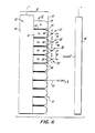
- Figure 1 illustrates a magnetic recording medium 10 comprising this invention. This illustration is materially enlarged for purposes of better understanding the microstructure and properties of the magnetic recording layer 14.
- Layer or film 14 is deposited on the conductive support 12 by any suitable process, such as electrochemical plating. The conditions of the plating process should be selected such that the microstructure of the resulting magnetic film 14 will result in a multitude of substantially uniform acicular or columnar shaped crystallites or particles 16, with both the longitudinal axes of the acicles and the crystallographic "c" axis 18 of the particles 16 oriented perpendicular to the plane of the film.
- the crystalline materials comprising the film 14 under discussion herein and the later examples are HCP Co or Co based alloy particles.
- Examples of Co based alloys are CoRe, CoCr and CoNi.
- the film particles 16 are physicafly separated by impurities or voids 20 which exist in the grain boundary 22 between particles. If the medium consists of isolated acicular particles 16 having both the preferred oriented columnar shape and the crystal anistropy shown in Figure 1, the magnetic layer or film 14 will have strong uniaxial anisotropy with the easy axis of magnetization normal to the film plane, which renders the film highly suitable for perpendicular recording.
- preferred anisotropy is meant that the particles 16 have their crystal "c" axis 18 orientation substantially along the longitudinal axis of each acicular particle as well as the longitudinal axis of each acicular particle 16 aligned normal (substantially perpendicular) to the plane of the film 14.
- Figure 2 illustrates the ideal magnetic hysteresis loop representing the relation between the applied magnetic field, H, and magnetization, M, of the recording layer, as measured by a vibrating sample magnetometer over a large area of a film.
- Hysteresis loop 24 in solid line represents the ideal hysteresis characteristic for the perpendicular ( 1 ) magnetization direction when the magnetic film has a uniaxial anisotropy normal to the film plane and hysteresis loop 26 is dotted line represents the ideal hysteresis characteristic for the longitudinal (II) magnetization direction of the same film.
- the ideal perpendicular hysteresis loop 24 of the bulk film would be a parallelogram, i.e., slanted from a rectangle because of the demagnetizing field (H d ) effect along the direction opposed to the easy magnetizing direction.
- the intrinsic hystersis loop of the particle for a high uniaxial anisotropic film should be of rectangular shape without any slanting, as illustrated by the hysteresis loop 28 in Figure 3.
- the linear distance between reversed magnetization regions becomes quie small and hence the demagnetizing field, H d , within a single magnetized bit area reduces or approaches zero with shortening wavelength. Consequently, the magnetic hysteresis loop of such a magnetized area under high density recording will behave as an intrinsic loop 28 illustrated in Figure 3.
- the remanence, M r of the magnetized area will approach the value of the saturation magnetization, M s , of the magnetized area. It is this physical fact of correlating the magnetic hysteresis loop of the bulk film to the intrinsic loop of the magnetized bit area that impels the search for obtaining a better perpendicular recording medium by determining whether the perpendicular hysteresis loop of the bulk film, as measured from a vibrating sample magnetometer, results in a good parallelogram shaped hysteresis loop 30 of Figure 3, which is similar shape to that represented by loop 24 of Figure 2.
- the slanting of the hysteresis loop 30 of the bulk film or long wavelength recording area from the rectangular intrinsic loop 28, is caused by the demagnetizing field, H d .
- the extent of the demagnetizing field, H d can be reduced by either decreasing the magnetization, M s , of the medium by means of doping with an alloy element, such as Cr or Re, or by increasing the separation between the particles 16, i.e., increasing the magnitude of the grain boundary 22.
- an alloy element such as Cr or Re
- perpendicular magnetization hysteresis loops as measured from the bulk film, in practice, would show some inclination and the parallel loop would show some residual magnetism.
- a typical example of these parallel (II) and perpendicular ( 1 ) magnetization hysteresis loops are respectively illustrated in Figure 4A as loops 32 and 34. The amount of the inclination and the relative inclination between the two loops is related to the strength of demagnetizing field, H d , in the film.
- a post-electroplating treatment may be employed to enhance the size of the grain boundary 22 between the particles.
- Several such treatments are possible. These treatments are based on the principles of enhanced grain boundary diffusion and enhanced grain boundary etching. These treatments are explained in conjunction with the schematic illustrations of Figures 7 and 8.
- Figure 7 illustrates the change in particle microstructure during the enhanced grain boundary diffusion treatment of the electroplated film 14.
- a magnetic film 14 electroplated on the surface of the substrate 12 is placed in an environment comprising a reactant, R, and identified at 63.
- the reactant may be a gas, such as, hydrogen, oxygen, nitrogen or other diffusion agent or the vapor phase of an element that is dissimilar to the film material. If the kinetics for diffusion of the reactant 63 are sufficiently high, then the reactant 63 would undergo a solid state diffusion into the particle 16 of the film 14. This diffusion is either through the exposed surface of the particle and directly into the particle bulk, as indicated by the arrows 62, or initially through the grain boundary 22 and then into the particle bulk, as indicated by the arrow 64.
- the reactant 63 diffuses into the Co or Co-based alloy particles 16, it forms a nonmagnetic phase compound or solid solution, identified as region 66, with the Co or Co alloy around the exterior regions of each particle, leaving the nondisturbed magnetic particle or core portion 68.
- the diffusion of a second species into the particle will be more than one order of magnitude faster along the grain boundary 22 via path 65 than directly into the bulk of the particle via path 62 or transversely into the particle side walls via paths 64. Therefore, the enhanced grain boundary diffusion treatment will create a layer of nonmagnetic phase around each particle 16, illustrated by shaded region 66 of Figure 7. Consequently, the untouched magnetic material in the core portion 68 of each particle which has not been exposed to the diffusion treatment will retain its original magnetic moment and acicular shape.
- the effective magnetic separation between adjacent magnetic core portions 68 of the particles 16 will be increased because of the formation of the nonmagnetic phase portion 66 in the region between the particle core portion 68. This increase in the separation between the original magnetic particles 16 will result in a reduction of the demagnetising field, H d , of each particle and a corresponding increase in its coercivity.
- an oxidation treatment at elevated temperature can be employed.
- this type of oxidation as a film treatment.
- the heat treatment of the particles will subject them to an annealing effect.
- improved HCP Co alloy particles can, in principal, be achieved because of reduction in crystal strain and/or stacking faults in the particles.
- the annealing effect would also increase the crystalline anisotropy.
- the formation of the intergranular oxide along the grain boundaries and grain front of the particles provides a harder and more stable film, increasing its archival properties.
- Another treatment for increasing the effective separation between the magnetic particles 16 is by employing enhanced grain boundary etching of the plated film 14 which is schematically illustrated in Figure 8.
- the rate of removal of total material is faster along the grain boundary 22 than at the regions on the surface of the particles 16, i.e., the region of terminated particle growth at interface 52 in immediate contact with the etching reagent.
- an electroplated film 14 on an accompanying substrate 12 is placed in a chemical or electrochemical etching solution comprising an etching reagent, E, identified at 70 in Figure 8, the reagent 70 immediately attacks the particle 16 atthe grain front 72 at the surface of the particle as well as along grain boundary 22.
- the rate of removal of the magnetic material along the grain boundary 22 and in the vicinity or regions 74 of the grain boundary 22 would be greater than the grain front 72. This is because (1) the grain boundary 22 possesses higher free energy and, consequently, tends toward a greater rate of etching than the grain section proper of the particles and (2) the grain boundary 22 of the electroplated film includes inclusions, such as, Co(OH) 2 , which are highly soluble in the acid solution and, hence, open up the grain boundary regions for the attending etchant.
- the particle material 75 is removed from the particles 16, leaving a core portion 78 of each particle intact if the etching process is stopped at a proper time.
- the core portions 78 of the particles will retain their original magnetic moment and acicular shape but have a larger interparticle separation as is evident from Figure 8.
- the effective magnetic separation between adjacent magnetic core portions 78 of the particles 16 will be increased because of the removal of the portions 75 in the regions surrounding the particles. This increase in the separation between the magnetic particles will result in a reduction of the demagnetising field, H d , of each particle.
- particle separation may be further extended by a combination of either intergranular diffusion or oxidation and chemical etching.
- the treatments for electroplated films we propose here for the reduction of demagnetizing field of the particles by the enhanced grain boundary diffusion or enhanced grain boundary etching can also be applied to magnetic films initially prepared by other methods of fabrication, such as, for example, sputtered CoCr or CoRe alloy films or vacuum deposited magnetic alloy films, as long as the microstructure of the particles in the film exhibit columnar or acicular shaped structures with the longitudinal axis of the columnar or acicular particles and the "c" axis of the HCP particle crystal comprising the particles are oriented normal to the plane of the film.
- the magnetic record medium subjected to the further treatment method of this invention is as shown in Figure 1, i.e. with magnetic acicles perpendicular to the surface of the film, and with the crystallographic 'c' axis virtually collinear with the longitudinal axis of each acicle.
- This example relates to electroplated Co films followed by enhanced grain boundary reaction.
- the treatment is an enhanced grain boundary diffusion accomplished by an electrochemical cathodic treatment of the magnetic film.
- Cathodic treatment comprises the employment of an acid solution of 0.1 mole/liter of thiorea and 30 cc/liter of H 2 SO 4 (concentrated).
- an applied voltage between the Co sample as cathode 48 and the anode 46 hydrogen generated by cathodic action of the solution will diffuse into the film.
- the rate of diffusion of hydrogen will be faster along the grain boundary 22 of the film 14 than into the crystallite bulk, particularly at the grain front 52. Consequently, the spacing between the acicular crystallites will be occupied by a nonmagnetic Co-H compound or alloy thereby increasing the separation between the crystallites while decreasing the demagnetising field, H d .
- Figures 17A, B, C and D show the perpendicular and parallel magnetic hysteresis loops for these four film samples, respectively.
- This example relates to electroplated Co films followed by another kind of enhanced grain boundary reaction.
- the treatment is an enhanced grain boundary etching accomplished by an anodizing treatment of the magnetic film.
- Figures 18A, B, and C show the parallel (II) and perpendicular (J magnetic hysteresis loops 122 and 124, 126 and 128, and 132 and 134, respectively, for these three film samples.
- anodization effectively reduces the demagnetising field, H d , as indicated by the decrease in inclination of perpendicular ( 1 ) hysteresis loops 124, 128 and 134 in comparison with the perpendicular ( 1 ) hysteresis loop 104 of the untreated film of Figure 17A and, hence, increase the ratio of M r /M s and increase the coercivity He, of the magnetic Co film by electrochemically etching away and material between the crystallites, which effectively increases their separation.
- This anodizing treatment and the cathodic treatment of Example 1 demonstrate that by using the technique of enhanced grain boundary etching under electrochemical method, the separation between the acicular crystallites can effectively increase and, hence, reduce the demagnetising effect as well as increase the values for He and M r . Therefore, one can use these treatment techniques to tailor a film for particular hysteresis properties desired for specific perpendicular recording applications.
- This example relates to electroplated Co films followed by still another kind of treatment.
- the treatment is an enhanced grain boundary etching accomplished by a chemical etching treatment of the magnetic film in an acid bath.
- An etchant bath was prepared in an etching tank comprising concentrated H 2 SO 4 solution of 0.1 mole/liter.
- the film sample was placed in the acid bath and material was preferentially etched away along the grain boundary 22 at a faster rate than the bulk of the acicular crystallite. This resulted in increased intercrystallic separation.
- Table III shows the etching treatment time and bath temperature for the sample.
- Examples 1 through 4 are not limited to films produced by electroplating method described herein. These treatments may readily be applied to other magnetic films fabricated by other methods that provide the film with perpendicular anisotropy useful for perpendicular recording. In this Example, enhanced grain boundary diffusion is applied to a film having perpendicular anisotropy fabricated from a conventional sputtering process.
- Sputtered Co-Re alloy films were produced with conventional sputtering equipment to have preferred orientation in crystallographic and crystallite shape similar to that of the electroplated films previously discussed.
- the method and conditions of obtaining the preferred oriented film is similar to the process described in the previous publication entitled "High Coercivity and High Hysteresis Loop Squareness of Sputtered Co-Re Thin Film” by Tu Chen and G B Charlan published in the Journal of Applied Physics, Volume 50, page 4285 et al., 1979.
- the sample produced for this example was sputtered from alloy target consisting of Co plus 10 atomic per cent Re. The sputtering was carried out under a 75 p m argon pressure.
- the film was deposited on the glass substrate at 100°C with deposition rate of 0.05 nm per second until a total film thickness of about 300 nm was achieved.
- the film as deposited showed perfect anisotropy with "c" axis of all crystallites in the film oriented normal to the film plane as revealed by the x-ray difraction method described in connection with Figures 9A and 9B.
- perpendicular anisotropy with accompanying reduction of the demagnetizing field is accomplished by reducing the magnetization of the film through alloying Co with Re. Therefore, for these as-deposited sputtered films, their demagnetising field H d , and coercivity, He, cannot be improved beyond the limits of these properties now known to be obtained in conventional sputtered fabrication.
- the enhanced grain boundary diffusion treatment is applied to the previously sputtered Co-Re film samples to increase the magnetic separation between the crystallites and thereby decrease the H d and increase the M/Ms ratio and the He.
- a sputtered film designated as Co-Re 121478-01 was heat treated in an ambient atmosphere in a furnace at 300°C for 18 hours to enhance the grain boundary diffusion by oxidation.
- a sputtered film designated as Co-Re 121478-01 was heat treated in an ambient atmosphere in a furnace at 300°C for 18 hours to enhance the grain boundary diffusion by oxidation. This illustrates that the enhanced grain boundary diffusion principle can also be applied also to sputtered films having perpendicular anistropy.
- Magnetic materials and alloys other than Co or Co alloys may be used.
Landscapes
- Engineering & Computer Science (AREA)
- Power Engineering (AREA)
- Manufacturing & Machinery (AREA)
- Manufacturing Of Magnetic Record Carriers (AREA)
- Magnetic Record Carriers (AREA)
Claims (8)
Applications Claiming Priority (4)
| Application Number | Priority Date | Filing Date | Title |
|---|---|---|---|
| US06/306,125 US4405677A (en) | 1981-09-28 | 1981-09-28 | Post treatment of perpendicular magnetic recording media |
| US06/306,126 US4374009A (en) | 1981-09-28 | 1981-09-28 | Electrochemical post treatment of perpendicular magnetic recording media |
| US306125 | 1989-02-06 | ||
| US306126 | 1999-05-06 |
Publications (2)
| Publication Number | Publication Date |
|---|---|
| EP0076142A1 EP0076142A1 (de) | 1983-04-06 |
| EP0076142B1 true EP0076142B1 (de) | 1987-09-16 |
Family
ID=26974984
Family Applications (1)
| Application Number | Title | Priority Date | Filing Date |
|---|---|---|---|
| EP19820305103 Expired EP0076142B1 (de) | 1981-09-28 | 1982-09-28 | Nachbehandlung von senkrecht magnetisierbarem Aufzeichnungsträger |
Country Status (2)
| Country | Link |
|---|---|
| EP (1) | EP0076142B1 (de) |
| DE (1) | DE3277337D1 (de) |
Family Cites Families (3)
| Publication number | Priority date | Publication date | Assignee | Title |
|---|---|---|---|---|
| JPS5121562B2 (de) * | 1972-04-14 | 1976-07-03 | ||
| GB1599161A (en) * | 1976-07-15 | 1981-09-30 | Matsushita Electric Industrial Co Ltd | Magnetic recording medium and method of making the same |
| US4137342A (en) * | 1976-10-29 | 1979-01-30 | Minnesota Mining And Manufacturing Company | Cobalt-doped acicular hyper-magnetite particles |
-
1982
- 1982-09-28 EP EP19820305103 patent/EP0076142B1/de not_active Expired
- 1982-09-28 DE DE8282305103T patent/DE3277337D1/de not_active Expired
Also Published As
| Publication number | Publication date |
|---|---|
| EP0076142A1 (de) | 1983-04-06 |
| DE3277337D1 (en) | 1987-10-22 |
Similar Documents
| Publication | Publication Date | Title |
|---|---|---|
| US4780781A (en) | Thin film magnetic head having magnetic film of Co-Ni-Fe alloy | |
| JP3229718B2 (ja) | 軟磁性合金、軟磁性薄膜および多層膜 | |
| US5976326A (en) | Method of sputtering selected oxides and nitrides for forming magnetic media | |
| CA1315612C (en) | Perpendicular magnetic storage medium | |
| US4388367A (en) | Perpendicular magnetic recording medium and fabrication | |
| EP0008328A1 (de) | Amorphe magnetische Filme und ein Verfahren zur Herstellung solcher Filme | |
| US4405677A (en) | Post treatment of perpendicular magnetic recording media | |
| US4374009A (en) | Electrochemical post treatment of perpendicular magnetic recording media | |
| GB2175014A (en) | Perpendicular magnetic recording medium | |
| Inagaki et al. | Ferrite thin films for high recording density | |
| EP0673021A1 (de) | Magnetische Aufzeichnungsmedium sowie Verfahren zu seiner Herstellung | |
| JP2003157509A (ja) | 薄膜磁気ヘッド及びその製造方法、並びにそれを搭載した磁気ディスク装置 | |
| EP0076142B1 (de) | Nachbehandlung von senkrecht magnetisierbarem Aufzeichnungsträger | |
| US4609593A (en) | Magnetic recording medium | |
| US5571573A (en) | Process of forming magnetic devices with enhanced poles | |
| JP2001134927A (ja) | 磁気記録媒体 | |
| JPH0323972B2 (de) | ||
| US4641213A (en) | Magnetic head | |
| JP3869550B2 (ja) | 磁気記録媒体および磁気記憶装置 | |
| JP2796092B2 (ja) | 記録媒体膜製造方法 | |
| JP2897485B2 (ja) | 軟磁性薄膜およびその製造方法 | |
| JPH0315245B2 (de) | ||
| JPH0256724B2 (de) | ||
| JPH04366417A (ja) | 磁気記録媒体およびその製造方法 | |
| KR100333496B1 (ko) | 고보자력 자성박막 열처리 방법 |
Legal Events
| Date | Code | Title | Description |
|---|---|---|---|
| PUAI | Public reference made under article 153(3) epc to a published international application that has entered the european phase |
Free format text: ORIGINAL CODE: 0009012 |
|
| AK | Designated contracting states |
Designated state(s): DE FR GB IT NL |
|
| 17P | Request for examination filed |
Effective date: 19831005 |
|
| GRAA | (expected) grant |
Free format text: ORIGINAL CODE: 0009210 |
|
| AK | Designated contracting states |
Kind code of ref document: B1 Designated state(s): DE FR GB IT NL |
|
| ET | Fr: translation filed | ||
| REF | Corresponds to: |
Ref document number: 3277337 Country of ref document: DE Date of ref document: 19871022 |
|
| ITF | It: translation for a ep patent filed | ||
| PLBE | No opposition filed within time limit |
Free format text: ORIGINAL CODE: 0009261 |
|
| STAA | Information on the status of an ep patent application or granted ep patent |
Free format text: STATUS: NO OPPOSITION FILED WITHIN TIME LIMIT |
|
| 26N | No opposition filed | ||
| PGFP | Annual fee paid to national office [announced via postgrant information from national office to epo] |
Ref country code: FR Payment date: 19890613 Year of fee payment: 8 |
|
| PGFP | Annual fee paid to national office [announced via postgrant information from national office to epo] |
Ref country code: DE Payment date: 19890831 Year of fee payment: 8 |
|
| ITTA | It: last paid annual fee | ||
| PGFP | Annual fee paid to national office [announced via postgrant information from national office to epo] |
Ref country code: NL Payment date: 19890930 Year of fee payment: 8 Ref country code: GB Payment date: 19890930 Year of fee payment: 8 |
|
| PG25 | Lapsed in a contracting state [announced via postgrant information from national office to epo] |
Ref country code: GB Effective date: 19900928 |
|
| PG25 | Lapsed in a contracting state [announced via postgrant information from national office to epo] |
Ref country code: NL Effective date: 19910401 |
|
| NLV4 | Nl: lapsed or anulled due to non-payment of the annual fee | ||
| GBPC | Gb: european patent ceased through non-payment of renewal fee | ||
| PG25 | Lapsed in a contracting state [announced via postgrant information from national office to epo] |
Ref country code: FR Effective date: 19910530 |
|
| PG25 | Lapsed in a contracting state [announced via postgrant information from national office to epo] |
Ref country code: DE Effective date: 19910601 |
|
| REG | Reference to a national code |
Ref country code: FR Ref legal event code: ST |