EP0075513B1 - Piston à clapets pour amortisseur - Google Patents
Piston à clapets pour amortisseur Download PDFInfo
- Publication number
- EP0075513B1 EP0075513B1 EP82401673A EP82401673A EP0075513B1 EP 0075513 B1 EP0075513 B1 EP 0075513B1 EP 82401673 A EP82401673 A EP 82401673A EP 82401673 A EP82401673 A EP 82401673A EP 0075513 B1 EP0075513 B1 EP 0075513B1
- Authority
- EP
- European Patent Office
- Prior art keywords
- disc
- piston
- lateral
- piston according
- periphery
- Prior art date
- Legal status (The legal status is an assumption and is not a legal conclusion. Google has not performed a legal analysis and makes no representation as to the accuracy of the status listed.)
- Expired
Links
Images
Classifications
-
- F—MECHANICAL ENGINEERING; LIGHTING; HEATING; WEAPONS; BLASTING
- F16—ENGINEERING ELEMENTS AND UNITS; GENERAL MEASURES FOR PRODUCING AND MAINTAINING EFFECTIVE FUNCTIONING OF MACHINES OR INSTALLATIONS; THERMAL INSULATION IN GENERAL
- F16F—SPRINGS; SHOCK-ABSORBERS; MEANS FOR DAMPING VIBRATION
- F16F9/00—Springs, vibration-dampers, shock-absorbers, or similarly-constructed movement-dampers using a fluid or the equivalent as damping medium
- F16F9/32—Details
- F16F9/34—Special valve constructions; Shape or construction of throttling passages
Definitions
- the invention relates to hydraulic shock absorbers comprising a piston which slides in a cylinder which it separates into two chambers containing liquid and which is provided with several passages capable of connecting the two chambers, each passage being closed by a valve opening. when the piston slides in one of the two directions, allowing a braked flow of liquid from one chamber to the other.
- a damper In document FR-A-2 360 800, a damper is described, the piston of which generally comprises, fixed on a piston rod coaxial with. cylinder, a central body and two lateral parts called limiters, carrying the valves and arranged axially on either side of the body.
- This comprises a cylindrical periphery providing guidance in the bore of the cylinder and two faces perpendicular to the axis of the cylinder; it is crossed by passages each opening on both sides by circular orifices.
- Each side piece has a periphery spaced from the bore of the cylinder and is crossed by holes aligned with those of the body and each containing a helical spring which pushes a circular valve against the wall forming the seat of one of the orifices of the body. The spacing between each valve and its seat is limited by the stop of the valve against a bearing face of the limiter.
- Such pistons have the advantage of allowing precise metering of the limitation or braking of the flow - and therefore of the damping characteristic - in each direction of displacement of the piston, by appropriately dimensioning each valve spring and each spacing between the bearing faces of the lateral parts and the opposite face of the body.
- they have the drawback of being relatively bulky in the axial direction, due to the superposition of the body and the two lateral parts; the result is, for a given cylinder, a reduced stroke of the piston and its rod, a stroke which is likely to be insufficient in particular if it is a shock absorber for suspension of a motor vehicle whose maximum deflections must be sufficient important for satisfying comfort and large load variations.
- the object of the invention is to remedy this drawback and to propose a damper piston which is less bulky in the axial direction.
- a piston comprising, fixed to a rod, a central part and two lateral parts arranged axially on either side of this central part, the central part and the lateral parts comprising aligned axial passages closed by valves received in the lateral parts and cooperating with seats delimited by the central part, characterized in that the central part is a thin disc whose diameter is less than the maximum diameter of the piston and in that at least one of the two lateral parts carries its periphery a guide ring.
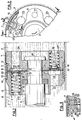
- a piston 3 is slidably mounted separating this cylinder into two chambers 4, 5 filled with liquid.
- the piston comprises two lateral parts 6, 7 called limiters, which enclose a central part constituted by a perforated disc 8 and which are fixed for example by crimping on the end 9a of a rod 9 coaxial with the axis of the cylinder.
- Each part 6, 7 has at its periphery a cylindrical surface 10, 11 extending between an end face 12, 13 adjacent to the disc 8 and a radial shoulder 14, 15. Between the two shoulders 14,15 is held axially a split ring 16 made of plastic with a low coefficient of friction, the outer surface of which guides the piston in bore 1.
- the slot in the ring allows it to be easily mounted and is supported in known manner to prevent liquid flows there from one of the chambers 4, 5 towards the other.
- Each part 6, 7 is crossed parallel to the axis, by two series of holes: some 17, 18 each contain a helical spring 19, 20 which pushes a circular valve 21, 22 against its seat constituted by the contour of one of the perforations of the disc 8; the others 23, 24 face the holes of the first series of the other side piece.
- Each hole 17, 18 has an open bottom 17a, 18a, serving as a spring support, and opens, on the side of the disc, in a large annular groove 25, 26 formed in the face 12, 13 of the activator: around each hole , the bottom 27 of this groove has a boss 28 or a rebate 29 constituting a bearing face parallel to the disc and serving as a stop for a flange 30 of the valve when the latter departs from its seat.
- the disc 8 is made of cut thin sheet metal and has circular perforations 31 in line with the holes 17, 18 of the parts 6, 7. These perforations are produced directly by fine cutting.
- an axial projection 32 of the part 6 is engaged with a slight or zero angular play J in an opening 33 of the disc and in a recess 34 of the part 7.
- a prominence 35 in the groove 26 faces an equivalent prominence 36 in the groove 25 of the part 6 so that the outer contour, like the lower contour, of the faces 12 and 13 of the parts 6, 7 ensures continuous tight contact against the disc, preventing in particular any leakage of liquid from the holes 23, 24 towards the peripheries 10, 11, leakage which would disturb the law of braking of flow of the damper.
- permanent leakage passages can be arranged, in a manner not shown, either by at least one calibrated conduit passing through a valve or the disc 8 and possibly the parts 6, 7, conduit in particular formed by an axial groove in the bore. receiving the rod 9 or by an additional perforation of the disc 8, either by slight deformation of the sheet on the contour of at least one perforation 31, forming a hollow in the corresponding valve seat, or again by cutting a notch in this outline.
- valves 22 located to the right of the disc 8 closed and pushes the valves 21 located to the left.
- Each valve 21 moves away from its seat by compressing the spring, allowing liquid to flow from chamber 5 to chamber 4, when the sliding speed of the piston reaches a determined value; the valve lift, that is to say its spacing relative to its seat, becomes maximum when its flange 30 abuts against the bearing face 28, and provides a determined braking of the flow.
- the various valves are associated with springs tared differently and the spacings between the flanges 30 of the various valves and the corresponding bearing faces 28, 29 may differ, as well as, as a result, the maximum lift of the valves, determining various flow brakes.
- the ring 16 is carried by the periphery of a single lateral part, the axial retention of the ring then being carried out on the side opposite the shoulder such as 14, either by the contour of the other limiter, or by that of the disc, then planned slightly larger than in the previous case.
- the proposed piston is not only of short axial length compared to existing ones of the same type, and lighter, which is particularly advantageous in the case of shock absorbers used on motor vehicles, but even less expensive, in particular thanks to the simplicity of manufacture. valve seats, without machining.
Landscapes
- Engineering & Computer Science (AREA)
- General Engineering & Computer Science (AREA)
- Mechanical Engineering (AREA)
- Fluid-Damping Devices (AREA)
Applications Claiming Priority (2)
| Application Number | Priority Date | Filing Date | Title |
|---|---|---|---|
| FR8117908 | 1981-09-23 | ||
| FR8117908A FR2513340A1 (fr) | 1981-09-23 | 1981-09-23 | Piston a clapets pour amortisseur |
Publications (2)
| Publication Number | Publication Date |
|---|---|
| EP0075513A1 EP0075513A1 (fr) | 1983-03-30 |
| EP0075513B1 true EP0075513B1 (fr) | 1984-12-19 |
Family
ID=9262384
Family Applications (1)
| Application Number | Title | Priority Date | Filing Date |
|---|---|---|---|
| EP82401673A Expired EP0075513B1 (fr) | 1981-09-23 | 1982-09-14 | Piston à clapets pour amortisseur |
Country Status (5)
| Country | Link |
|---|---|
| US (1) | US4497394A (cg-RX-API-DMAC7.html) |
| EP (1) | EP0075513B1 (cg-RX-API-DMAC7.html) |
| DE (1) | DE3261631D1 (cg-RX-API-DMAC7.html) |
| ES (1) | ES274687Y (cg-RX-API-DMAC7.html) |
| FR (1) | FR2513340A1 (cg-RX-API-DMAC7.html) |
Families Citing this family (15)
| Publication number | Priority date | Publication date | Assignee | Title |
|---|---|---|---|---|
| DE3338781A1 (de) * | 1983-10-26 | 1985-05-09 | Wabco Westinghouse Steuerungstechnik GmbH & Co, 3000 Hannover | Druckmittelbetaetigbarer arbeitszylinder mit einer einrichtung zum daempfen der endabbremsung des arbeitskolbens |
| FR2602291B1 (fr) * | 1986-07-30 | 1990-08-24 | Peugeot | Amortisseur hydraulique a clapets guides |
| US5161822A (en) * | 1990-11-26 | 1992-11-10 | Tlc Suspension | Tilt correction system |
| DE4239160C1 (de) * | 1992-11-21 | 1994-05-11 | Bilstein August Gmbh Co Kg | Regelbarer hydraulischer Schwingungsdämpfer für Kraftfahrzeuge |
| ES2124111B1 (es) * | 1994-11-15 | 1999-08-16 | Sintermetal Sa | Conjunto de embolo y guia de su vastago para amortiguadores hidraulicos. |
| US7070028B2 (en) | 2001-02-07 | 2006-07-04 | Tenneco Automotive Operating Company Inc. | Frequency dependent damper |
| US20050056507A1 (en) * | 2003-09-15 | 2005-03-17 | Molina Simon Anne De | Shock absorber staged valving system |
| WO2010091481A1 (en) * | 2009-02-16 | 2010-08-19 | Phillip Di Maria | Active suspension system and hydraulic ram therefor |
| CN105546027B (zh) * | 2016-01-22 | 2018-02-27 | 中铁大桥勘测设计院集团有限公司 | 设有泄压装置的粘滞阻尼器 |
| CN106194877B (zh) * | 2016-08-30 | 2018-06-19 | 北京机械设备研究所 | 一种多级同步伸缩油缸流量补偿装置 |
| US10300757B2 (en) * | 2017-05-09 | 2019-05-28 | Gm Global Technology Operations Llc. | Hydraulic mount apparatus and a suspension system that utilizes the hydraulic mount apparatus |
| CN108240370B (zh) * | 2018-02-09 | 2020-09-15 | 武汉船用机械有限责任公司 | 缓冲活塞 |
| CN111536186B (zh) * | 2019-05-06 | 2021-07-23 | 北京京西重工有限公司 | 阻尼器组件和用于阻尼器组件的活塞 |
| CN111255847B (zh) * | 2020-01-17 | 2021-12-03 | 常州中车柴油机零部件有限公司 | 一种轨道车辆减振器 |
| FR3124837B1 (fr) * | 2021-07-01 | 2023-10-27 | Psa Automobiles Sa | Amortisseur hydraulique de suspension de véhicule automobile |
Family Cites Families (12)
| Publication number | Priority date | Publication date | Assignee | Title |
|---|---|---|---|---|
| US1455265A (en) * | 1923-05-15 | Shock absorber | ||
| US16582A (en) * | 1857-02-10 | Improved raking attachment for reapers | ||
| US1457122A (en) * | 1920-04-13 | 1923-05-29 | Albert C Ree | Shock absorber |
| USRE16582E (en) | 1926-04-13 | 1927-04-05 | Shock absobbeb | |
| US2877071A (en) * | 1956-10-23 | 1959-03-10 | Emmanuel Kaye | Seals for pistons, glands and the like |
| US2986125A (en) * | 1959-07-30 | 1961-05-30 | Gen Motors Corp | Vacuum motor |
| US3139008A (en) * | 1960-04-27 | 1964-06-30 | Arnt U Haanes | Reciprocatory pneumatic motor |
| US4050359A (en) * | 1975-09-04 | 1977-09-27 | Brunswick Corporation | Hydraulic power trim and power tilt system supply |
| US4085925A (en) * | 1976-03-31 | 1978-04-25 | Carl Ullrich Peddinghaus | Hydro-pneumatic shock absorber |
| FR2360800A1 (fr) * | 1976-05-24 | 1978-03-03 | Peugeot | Amortisseur hydraulique perfectionne |
| IT1121553B (it) * | 1979-06-01 | 1986-04-02 | Cattaneo Leopoldo | Fasce elastiche e/o raschiaolio per motori termici e/o per tenute di qualsiasi tipo,con rigidita'periferica e deformazione in funzionamento a caldo controllata mediante intagli,fori,alleggerimenti e fessure praticati sulle superfici piane di appoggio della fascia elastica nella sede e metodi per la loro produzione |
| JPS5733240A (en) * | 1980-08-07 | 1982-02-23 | Nissan Motor Co Ltd | Shock absorber |
-
1981
- 1981-09-23 FR FR8117908A patent/FR2513340A1/fr active Granted
-
1982
- 1982-08-16 ES ES1982274687U patent/ES274687Y/es not_active Expired
- 1982-09-08 US US06/416,023 patent/US4497394A/en not_active Expired - Fee Related
- 1982-09-14 DE DE8282401673T patent/DE3261631D1/de not_active Expired
- 1982-09-14 EP EP82401673A patent/EP0075513B1/fr not_active Expired
Also Published As
| Publication number | Publication date |
|---|---|
| DE3261631D1 (en) | 1985-01-31 |
| ES274687U (es) | 1984-05-16 |
| FR2513340B1 (cg-RX-API-DMAC7.html) | 1984-01-13 |
| EP0075513A1 (fr) | 1983-03-30 |
| US4497394A (en) | 1985-02-05 |
| FR2513340A1 (fr) | 1983-03-25 |
| ES274687Y (es) | 1984-12-16 |
Similar Documents
| Publication | Publication Date | Title |
|---|---|---|
| EP0075513B1 (fr) | Piston à clapets pour amortisseur | |
| EP0639726B1 (fr) | Dispositif d'obturation monobloc à guide centreur lubrifié pour tube d'amortisseur hydraulique pressurisé | |
| FR2855140A1 (fr) | Dispositif d'absorption modulable d'energie a charges pyrotechniques d'une colonne de direction de vehicule automobile | |
| FR2476782A1 (fr) | Amortisseur pour suspension de vehicule automobile | |
| EP3071858A2 (fr) | Frein à disque à étrier coulissant à évacuation de l'air entre colonnettes et alésages | |
| FR2611844A1 (fr) | Assemblage de piston pour amortisseur hydraulique | |
| FR2677095A1 (fr) | Amortisseur a fluide precommande comportant une lame de soupapes presentant un contour interieur dentele. | |
| EP1600347B1 (fr) | Simulateur d'actionnement de frein, maître-cylindre pour frein de vehicule automobile, et procede de commande de ce simulateur | |
| FR2834028A1 (fr) | Soupape d'amortisseur | |
| JP7077779B2 (ja) | バルブ | |
| EP0882907A1 (fr) | Amortisseur à huile | |
| WO2006100406A1 (fr) | Dispositif d'amortissement a flux croises a deux couvercles sans indexage | |
| FR2914716A1 (fr) | Butee de compression hydraulique, notamment pour amortisseur hydraulique de suspension de vehicule automobile | |
| FR2973853A1 (fr) | Amortisseur hydraulique en particulier pour vehicule automobile | |
| EP0650427B1 (fr) | Maitre-cylindre tandem a desequilibre de pressions reduit | |
| FR2477655A1 (fr) | Dispositif a cylindre et piston, notamment pour la suspension de vehicules a moteur | |
| FR2875742A1 (fr) | Vehicule automobile muni d'un essieu a traverse deformable et a porte fusee de roue mobile longitudinalement | |
| EP3781835B1 (fr) | Amortisseur hydraulique avec amortissement inertiel à fluide pour la suspension d'un véhicule automobile | |
| FR3080162A1 (fr) | Amortisseur inertiel pour suspension de vehicule automobile | |
| EP1774195A2 (fr) | Dispositif d'amortisseur a deceleration asservie, et son application a l'amortissement de la colonne de direction escamotable d'un vehicule automobile | |
| FR3094435A1 (fr) | Amortisseur a double chambres inertielles pour suspension de vehicule automobile | |
| FR2636389A1 (fr) | Amortisseur, notamment pour systemes de suspension de roues de vehicules | |
| EP1767809B1 (fr) | Dispositif d'amortissement et amortisseur hydraulique comportant un tel dispositif | |
| EP4356026B1 (fr) | Actionneur pour un système de transmission de véhicule automobile | |
| EP3212951B1 (fr) | Disque d'embrayage pour embrayage a friction |
Legal Events
| Date | Code | Title | Description |
|---|---|---|---|
| PUAI | Public reference made under article 153(3) epc to a published international application that has entered the european phase |
Free format text: ORIGINAL CODE: 0009012 |
|
| AK | Designated contracting states |
Designated state(s): DE GB IT |
|
| RAP1 | Party data changed (applicant data changed or rights of an application transferred) |
Owner name: AUTOMOBILES CITROEN Owner name: AUTOMOBILES PEUGEOT |
|
| 17P | Request for examination filed |
Effective date: 19830219 |
|
| ITF | It: translation for a ep patent filed | ||
| GRAA | (expected) grant |
Free format text: ORIGINAL CODE: 0009210 |
|
| AK | Designated contracting states |
Designated state(s): DE GB IT |
|
| REF | Corresponds to: |
Ref document number: 3261631 Country of ref document: DE Date of ref document: 19850131 |
|
| PLBE | No opposition filed within time limit |
Free format text: ORIGINAL CODE: 0009261 |
|
| STAA | Information on the status of an ep patent application or granted ep patent |
Free format text: STATUS: NO OPPOSITION FILED WITHIN TIME LIMIT |
|
| 26N | No opposition filed | ||
| ITTA | It: last paid annual fee | ||
| PGFP | Annual fee paid to national office [announced via postgrant information from national office to epo] |
Ref country code: DE Payment date: 19950824 Year of fee payment: 14 |
|
| PGFP | Annual fee paid to national office [announced via postgrant information from national office to epo] |
Ref country code: GB Payment date: 19950908 Year of fee payment: 14 |
|
| PG25 | Lapsed in a contracting state [announced via postgrant information from national office to epo] |
Ref country code: GB Effective date: 19960914 |
|
| GBPC | Gb: european patent ceased through non-payment of renewal fee |
Effective date: 19960914 |
|
| PG25 | Lapsed in a contracting state [announced via postgrant information from national office to epo] |
Ref country code: DE Effective date: 19970603 |