EP0075498B1 - Cavity filter with coupling between non-adjacent cavities - Google Patents
Cavity filter with coupling between non-adjacent cavities Download PDFInfo
- Publication number
- EP0075498B1 EP0075498B1 EP19820401575 EP82401575A EP0075498B1 EP 0075498 B1 EP0075498 B1 EP 0075498B1 EP 19820401575 EP19820401575 EP 19820401575 EP 82401575 A EP82401575 A EP 82401575A EP 0075498 B1 EP0075498 B1 EP 0075498B1
- Authority
- EP
- European Patent Office
- Prior art keywords
- slot
- cavities
- coupling
- guide
- filter
- Prior art date
- Legal status (The legal status is an assumption and is not a legal conclusion. Google has not performed a legal analysis and makes no representation as to the accuracy of the status listed.)
- Expired
Links
- 238000010168 coupling process Methods 0.000 title claims description 32
- 238000005859 coupling reaction Methods 0.000 title claims description 32
- 230000008878 coupling Effects 0.000 title claims description 31
- 239000002184 metal Substances 0.000 claims description 3
- 210000000554 iris Anatomy 0.000 description 14
- 230000003313 weakening effect Effects 0.000 description 3
- 230000015572 biosynthetic process Effects 0.000 description 2
- 238000007796 conventional method Methods 0.000 description 2
- 230000007423 decrease Effects 0.000 description 2
- 238000003786 synthesis reaction Methods 0.000 description 2
- 238000013459 approach Methods 0.000 description 1
- 239000006185 dispersion Substances 0.000 description 1
- 230000000694 effects Effects 0.000 description 1
- 230000005684 electric field Effects 0.000 description 1
- 238000005516 engineering process Methods 0.000 description 1
- 238000004519 manufacturing process Methods 0.000 description 1
- 238000005259 measurement Methods 0.000 description 1
- 238000000034 method Methods 0.000 description 1
- 238000012552 review Methods 0.000 description 1
- 238000012546 transfer Methods 0.000 description 1
Images
Classifications
-
- H—ELECTRICITY
- H01—ELECTRIC ELEMENTS
- H01P—WAVEGUIDES; RESONATORS, LINES, OR OTHER DEVICES OF THE WAVEGUIDE TYPE
- H01P1/00—Auxiliary devices
- H01P1/20—Frequency-selective devices, e.g. filters
- H01P1/207—Hollow waveguide filters
- H01P1/208—Cascaded cavities; Cascaded resonators inside a hollow waveguide structure
Definitions
- the present invention relates to band pass type cavity filters.
- these filters are obtained by a series mounting of resonant cavities each tuned by a movable plunger (screw), the adjacent cavities being coupled together by irises or by rod curtains.
- the coupling coefficient existing between two adjacent cavities is defined by the opening of the iris or the spacing between the rod curtains according to the technology used and can be adjusted by means of a coupling screw which modifies the susceptance presented by the iris or the curtain of stems.
- Such filters have a symmetrical amplitude / frequency response, of the Chebchev type or of the Butterworth type.
- a filter having at least 4 cavities is folded back on itself in the middle so as to present a wall common to its two folded parts; in addition to the series coupling of the cavities, at least one coupling between two non-adjacent cavities is carried out (in the sense of the series mounting of the cavities) by means of an iris drilled in the common wall, at the place where it separates the two cavities considered.
- a description of these filters is given in an article written by John Rhodes published in the review "IEE Transactions on microwave theory and techniques" VoLMTT-18, No. 6, June 1970.
- the present invention aims to avoid the aforementioned drawbacks.
- the filter shown in fig. 1 is a bandpass type filter, produced in a waveguide of rectangular section, 1.
- the incident signal enters through an access E located at one end 3 of the guide and exits through an access S located at the other end 4 of the guide.
- the filter comprises a set of 6 cavities C1 to C6 arranged in series in the waveguide which is straight.
- the cavities are delimited by plates V1 to V7, the dimensions of which are the same as those of the section of the filter and each plate is provided with an iris 11 to 17.
- the iris 11 to 17 constitute the ports E and S of the filter .
- These cavities which are mounted in series, are electrically coupled by means of the irises 12 to 16. These irises are all aligned and their dimensions are determined so that they each have a given susceptibility with respect to the incoming electromagnetic wave. . This susceptance defines the value of the coupling coefficient between each cavity.
- the coupling coefficients are determined using coupling matrices according to conventional methods for calculating synthesis of the filters in order to obtain the desired characteristics in the desired bandwidth.
- Screws q1 to q7, emerging from the waveguide, are screwed respectively through the coupling plates V1 to V7 to open into the irises 11 to 17; by driving them into the irises, the screws make it possible to adjust the coupling coefficient by slightly modifying the susceptance of the irises.
- each cavity is adjusted using a tuning screw Q1 to Q6. All tuning screws are accessible for adjustment and are placed on the upper side of the filter.
- a housing 5 provided with a screw 6 is fixed under the lower face, 2, of the filter against which it is attached.
- a slit, L is cut, the length of which is determined by the distance which separates the cavities to be coupled in order to obtain a pseudo-elliptical response.
- This slot L which goes from the cavity C2 to the cavity C5 is arranged parallel to the longitudinal edges of the guide and its ends are located respectively at the middle of the cavities C2 and C5 in order to maintain the symmetry of the response and to obtain a good performance, because the slot L behaves like a slot line or an antenna and allows part of the energy to pass directly from the cavity C2 to the cavity C5.
- the ends of the slot have an enlarged part in the shape of T, B and B ', so as to amplify this phenomenon. Indeed, the widened slot ends make it possible to strongly couple the cavities C2 and C5 while there is practically no transfer of energy between the cavities C3 and C4 and the slot L due to the small width of the slot at the place where it cuts the bottom of these cavities.
- This embodiment is improved by adding two small antennas A, A ', which radiate respectively inside the cavities C2 and C5.
- Each antenna is constituted by a conducting wire, one of the ends of which is electrically connected to one end of the slot; A is connected to B and A 'is connected to B'.
- the slit L results in bringing an infinite attenuation on two frequencies located outside the pass band of the filter.
- the housing 5 of parallelepiped shape, shown in section in FIG. 3, is integral with the guide by its ends 8 and 9 which are welded respectively to the ends 3 and 4 of the guide.
- Fig. 3 shows that the housing 5 has a large opening in its wall contiguous to the face 2 of the guide. This opening is significantly wider than the slot L and is located in front of this slot.
- the box 5 makes it possible to guide the radiated energy coming from the slit and to limit a dispersion of this energy in space.
- the wall of the housing 5 opposite the slot L is crossed by a screw, 6, accessible from the outside of the filter to allow frequency adjustment.
- a screw, 6, accessible from the outside of the filter to allow frequency adjustment.
- this screw, 6, is provided at its end with a plate 7 of dimension greater than that of the end of the screw 6, the screw 6 is screwed onto the housing 5 facing the slot L.
- the driving in of the screw 6 deforms the electric field lines which are established around the slot L, which makes it possible to modify the coupling M 2 , 5 produced by the slot L.
- the screw 6 makes it possible to increase or decrease the value of the coupling produced, which has the consequence of varying the frequency of the two weakening peaks obtained by the coupling of the cavities C2 and C5.
- This frequency adjustment increases or decreases the value of the slopes of the filter response curve.
- the closer the end of the screw 6 to the slot L the weaker the coupling and therefore the more the infinite weakening point moves away from the central frequency and the more the slopes become flat.
- the farther the screw is from the slot the stronger the coupling and therefore the more the weakening point approaches the center frequency and the more the slopes stiffen.
- the slot makes it possible to correct the out-of-band response of the filter without significantly modifying the characteristics in the bandwidth.
- a filter with six blades that is to say with six cavities
- a slot coupling to obtain the same steepness of slope for the amplitude / frequency response curve, as with an eight pale filter.
- the coupling can be carried out with only one slot, that is to say without the antennas and without the housing or else with the slot and the antennas or the slot and the housing.
- the screw 6 is not essential; the value of the coupling then results, for a given slot, from the choice of the distance between the slot and the wall of the housing opposite the slot.
- housing 5 can be replaced by a simple metal plate placed at a suitable distance from the slot depending on the coupling and the shielding effect to be ensured.
Landscapes
- Control Of Motors That Do Not Use Commutators (AREA)
Description
La présente invention se rapporte aux filtres à cavités du type passe-bande.The present invention relates to band pass type cavity filters.
Classiquement ces filtres sont obtenus par un montage en série de cavités résonnantes accordées chacune par un plongeur mobile (vis), les cavités adjacentes étant couplées entre elles par des iris ou par des rideaux de tiges. Le coefficient de couplage existant entre deux cavités adjacentes est défini par l'ouverture de l'iris ou l'espacement entre les rideaux de tiges suivant la technologie utilisée et peut être ajusté au moyen d'une vis de couplage venant modifier la susceptance présentée par l'iris ou le rideau de tiges. De tels filtres ont une réponse amplitude/fréquence symétrique, du type Tchebychev ou de type Butterworth.Conventionally these filters are obtained by a series mounting of resonant cavities each tuned by a movable plunger (screw), the adjacent cavities being coupled together by irises or by rod curtains. The coupling coefficient existing between two adjacent cavities is defined by the opening of the iris or the spacing between the rod curtains according to the technology used and can be adjusted by means of a coupling screw which modifies the susceptance presented by the iris or the curtain of stems. Such filters have a symmetrical amplitude / frequency response, of the Chebchev type or of the Butterworth type.
Dans certains applications il est nécessaire d'obtenir des pointes d'affaiblissement infini à des fréquences données, situées de part et d'autre de la fréquence centrale et en dehors de la bande utile du filtre qui est déterminée par ses fréquences de coupures. La réponse amplitude/fréquence du filtre est alors qualifiée de réponse pseudo-elliptique. Pour obtenir ce type de réponse il est nécessaire d'effectuer un couplage entre certaines cavités non adjacentes; le choix de ces cavités résulte d'une étude faite à partir d'une méthode classique de synthèse des filtres. Dans la pratique, pour obtenir de tels couplages, un filtre ayant au moins 4 cavités, est replié sur lui- même en son milieu de façon à présenter une paroi commune à ses deux parties repliées; en plus du couplage en série des cavités, est effectué au moins un couplage entre deux cavités non adjacentes (au sens du montage en série des cavités) grâce à un iris percé dans la paroi commune, à l'endroit où elle sépare les deux cavités considérées. Une description de ces filtres est donnée dans un article écrit par John Rhodes paru dans la revue «IEE Transactions on microwave theory and techniques» VoLMTT-18, No. 6, June 1970.In certain applications it is necessary to obtain infinite attenuation peaks at given frequencies, located on either side of the central frequency and outside the useful band of the filter which is determined by its cut-off frequencies. The amplitude / frequency response of the filter is then called a pseudo-elliptical response. To obtain this type of response, it is necessary to perform coupling between certain non-adjacent cavities; the choice of these cavities results from a study made from a conventional method of synthesis of filters. In practice, to obtain such couplings, a filter having at least 4 cavities is folded back on itself in the middle so as to present a wall common to its two folded parts; in addition to the series coupling of the cavities, at least one coupling between two non-adjacent cavities is carried out (in the sense of the series mounting of the cavities) by means of an iris drilled in the common wall, at the place where it separates the two cavities considered. A description of these filters is given in an article written by John Rhodes published in the review "IEE Transactions on microwave theory and techniques" VoLMTT-18, No. 6, June 1970.
La réalisation de tels filtres est complexe et, de ce fait, le coût en est élevé.The production of such filters is complex and, therefore, the cost is high.
Une autre manière connue de réaliser de tels couplages consiste à percer un iris dans la paroi latérale de chacune des deux cavités non adjacentes à coupler et de transférer l'énergied'un iris à l'autre par un guide d'ondes accolé au filtre; un tel exemple est donné dans PATENT ABSTRACTS OF JAPAN, vol. 1, no. 156, 13 décembre 1977, page 8545 E 77 et dans le brevet japonais JP-A-52 100 955 qui y correspond. Mais il s'agit là encore d'une solution onéreuse étant donné qu'un guide d'ondes est relativement cher à réaliser.Another known way of making such couplings consists in piercing an iris in the side wall of each of the two non-adjacent cavities to be coupled and in transferring the energy from one iris to the other by a waveguide attached to the filter; such an example is given in PATENT ABSTRACTS OF JAPAN, vol. 1, no. 156, December 13, 1977, page 8545 E 77 and in the Japanese patent JP-A-52 100 955 which corresponds to it. However, this is again an expensive solution since a waveguide is relatively expensive to produce.
La presente invention a pour but d'éviter les inconvénients précités.The present invention aims to avoid the aforementioned drawbacks.
Ceci est obtenu au moyen d'un rétrocouplage par fente entre deux cavités d'un filtre à cavités. La présente invention sera mieux comprise et d'autre caractéristiques apparaîtront à l'aide de la description ci-après et des figures s'y rapportant qui représentent:
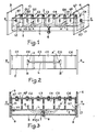
- la fig. 1, un filtre en guide d'ondes selon l'invention,
- la fig. 2, une vue d'un élément du filtre de la fig. 1, la fig. 3, une coupe longitudinale du filtre de la fig. 1.
- fig. 1, a waveguide filter according to the invention,
- fig. 2, a view of an element of the filter of FIG. 1, fig. 3, a longitudinal section of the filter of FIG. 1.
Le filtre représenté sur la fig. 1 est un filtre du type passe-bande, réalisé dans un guide d'ondes à section rectangulaire, 1. Le signal incident rentre par un accès E situé à une extrémité 3 du guide et sort par un accès S situé à l'autre extrémité 4 du guide. Le filtre comporte un ensemble de 6 cavités C1 à C6 disposées en série dans le guide d'ondes qui est droit.The filter shown in fig. 1 is a bandpass type filter, produced in a waveguide of rectangular section, 1. The incident signal enters through an access E located at one
Les cavités sont délimitées par des plaques V1 à V7, dont les dimensions sont les mêmes que celles de la section du filtre et chaque plaque est munie d'un iris 11 à 17. Les iris 11 à 17 constituent les accès E et S du filtre.The cavities are delimited by plates V1 to V7, the dimensions of which are the same as those of the section of the filter and each plate is provided with an
Ces cavités, qui sont montées en serie, sont couplées électriquement au moyen des iris 12 à 16. Ces iris sont tous alignés et leurs dimensions sont déterminées pour qu'ils présentent chacun vis-à-vis de l'onde électromagnétique entrante une susceptance donnée. Cette susceptance définit la valeur du coefficient de couplage entre chaque cavité.These cavities, which are mounted in series, are electrically coupled by means of the
Les coefficients de couplage sont déterminés à l'aide de matrices de couplage selon des méthodes classiques de calcul de synthèse des filtres pour obtenir les caractéristiques voulues dans la bande passante désirée.The coupling coefficients are determined using coupling matrices according to conventional methods for calculating synthesis of the filters in order to obtain the desired characteristics in the desired bandwidth.
Des vis q1 à q7, débouchant hors du guide d'ondes, sont vissées respectivement à travers les plaques de couplage V1 à V7 pour déboucher dans les iris 11 à 17; par leur enfoncement dans les iris, les vis permettent d'ajuster le coefficient de couplage en modifiant légèrement la susceptance des iris.Screws q1 to q7, emerging from the waveguide, are screwed respectively through the coupling plates V1 to V7 to open into the
La fréquence de résonance de chaque cavité est réglée à l'aide d'une vis d'accord Q1 à Q6. Toutes les vis d'accord sont accessibles pour le réglage et sont placées sur la face supérieure du filtre.The resonant frequency of each cavity is adjusted using a tuning screw Q1 to Q6. All tuning screws are accessible for adjustment and are placed on the upper side of the filter.
Un boîtier 5 muni d'une vis 6 est fixé sous la face inférieure, 2, du filtre contre laquelle il est accolé.A
Dans cette face inférieure 2, représentée sur la fig. 2, est découpée une fente, L, dont la longueur est déterminée par la distance qui sépare les cavités à coupler afin d'obtenir une réponse pseudo-elliptique. Cette fente L, qui va de la cavité C2 à la cavité C5 est disposée parallèlement aux arêtes longitudinales du guide et ses extrémités sont situées respectivement au niveau du milieu des cavités C2 et C5 afin de conserver la symétrie de la réponse et d'obtenir un bon rendement, car la fente L se comporte comme une ligne à fente ou une antenne et permet à une partie de l'énergie de passer directement de la cavité C2 à la cavité C5. De plus les extrémités de la fente présentent une partie élargie en forme de T, B et B', de manière à amplifier ce phénomène. En effet les extrémités de fente élargies permettent de coupler fortement les cavités C2 et C5 alors qu'il n'y a pratiquement pas de transfert d'énergie entre les cavités C3 etC4 et la fente L du fait de la faible largeurde la fente à l'endroit où elle coupe le fond de ces cavités.In this
Cette réalisation est améliorée en ajoutant deux petites antennes A, A', qui rayonnent respectivement à l'intérieur des cavités C2 et C5. Chaque antenne est constituée par un fil conducteur dont une des extrémités est reliée électriquement à une extrémité de la fente; A est reliée à B et A' est reliée à B'.This embodiment is improved by adding two small antennas A, A ', which radiate respectively inside the cavities C2 and C5. Each antenna is constituted by a conducting wire, one of the ends of which is electrically connected to one end of the slot; A is connected to B and A 'is connected to B'.
La fente L a pour résultat d'amener un affaiblissement infini sur deux fréquences situées hors de la bande passante du filtre.The slit L results in bringing an infinite attenuation on two frequencies located outside the pass band of the filter.
Le boîtier 5 de forme parallélépipédique, montré en coupe sur la fig. 3, est solidaire du guide par ses extrémités 8 et 9 qui sont soudées respectivement aux extrémités 3 et 4 du guide.The
La fig. 3 montre que le boîtier 5 présente une grande ouverture dans sa paroi accolée à la face 2 du guide. Cette ouverture est nettement plus large que la fente L et se trouve devant cette fente. Les antennes A et A' pénètrent respectivement à l'intérieur des cavités C2 et C5. Le boîtier 5 permet de guider l'énergie rayonnée issue de la fente et de limiter une dispersion de cette énergie dans l'espace.Fig. 3 shows that the
La paroi du boîtier 5 opposée à la fente L est traversée par une vis, 6, accessible de l'extérieur du filtre pour permettre un réglage en fréquence. Dans la réalisation particulière qui est décrite une seule vis est prévue; cette vis, 6, est munie à son extrémité d'un plateau 7 de dimension supérieure à celle de l'extrémité de la vis 6, la vis 6 est vissée sur le boîtier 5 face à la fente L. L'enfoncement de la vis 6 déforme les lignes de champ électrique qui s'établissent autour de la fente L, ce qui permet de modifier le couplage M2,5 réalisé par la fente L.The wall of the
La vis 6 permet d'augmenter ou de diminuer la valeur du couplage réalisé ce qui a pour conséquence de faire varier en fréquence les deux pointes d'affaiblissement obtenues par le couplage des cavités C2 et C5. Ce réglage en fréquence permet d'augmenter ou de diminuer la valeur des pentes de la courbe de réponse du filtre. En effet, plus l'extrémité de la vis 6 est rapprochée de la fente L, plus le couplage est faible et donc plus la pointe d'affaiblissement infini s'éloigne de la fréquence centrale et plus les pentes s'applatissent. Plus la vis est éloignée de la fente, plus le couplage estfort et donc plus la pointe d'affaiblissement se rapproche de la fréquence centrale et plus les pentes se raidissent.The
La fente permet de corriger la réponse hors bande du filtre sans pour autant modifier sensiblement les caractéristiques dans la bande passante. Ainsi il est possible, par exemple avec un filtre à six pâles (c'est-à-dire à six cavités), avec un couplage à fente d'obtenir la même raideur de pente pour la courbe de réponse amplitude/fréquence, qu'avec un filtre à huit pâles.The slot makes it possible to correct the out-of-band response of the filter without significantly modifying the characteristics in the bandwidth. Thus it is possible, for example with a filter with six blades (that is to say with six cavities), with a slot coupling to obtain the same steepness of slope for the amplitude / frequency response curve, as with an eight pale filter.
Le filtre qui vient d'être décrit à l'aide des figures est un filtre d'une longueur hors tout de 175 mm avec une section intérieure du guide d'ondes 1 de 28,499 x 12,624 mm. Pour un réglage donné de ce filtre les mesures ci-après ont été effectuées:
- - fréquence centrale de la bande passante: 7715 MHz
- - bande passante: 430 MHz
- - raideur des flancs de part et d'autre de la bande passante: chute de 60 dB sur 300 MHz sans le couplage par fente et chute de 60 dB sur 200 MHz avec le cuplage par fente.
- - center frequency of the bandwidth: 7715 MHz
- - bandwidth: 430 MHz
- - stiffness of the sides on either side of the bandwidth: fall of 60 dB on 300 MHz without coupling by slot and fall of 60 dB on 200 MHz with splitting by slot.
La description qui vient d'être faite portait sur un fittre'à six cavités à guide à section rectangulaire, mais l'invention s'applique également dans le cas où la-section du guide est carrée; d'ailleurs, dans les revendications, quand il sera question de guides rectangulaires il sera entendu que cette appellation couvrira les guides carrés. L'invention s'applique aussi au cas où le nombre de cavités est différent de six; il est toutefois à remarquer que le nombre de cavités doit au moins être égal à trois étant donné que le couplage par fente doit se faire entre deux cavités non adjacentes.The description which has just been made relates to a fitter ' with six cavities with guide with rectangular section, but the invention also applies in the case where the guide section is square; moreover, in the claims, when it comes to rectangular guides it will be understood that this designation will cover the square guides. The invention also applies to the case where the number of cavities is other than six; it should however be noted that the number of cavities must be at least equal to three since the coupling by slot must be made between two non-adjacent cavities.
Par ailleurs il est à noter que le couplage peut être effectué avec seulement une fente, c'est-à-dire sans les-antennes et sans le boîtier ou bien avec la fente et les antennes ou la fente et le boîtier. De même, dans le cas de l'utilisation d'un boîtier, la vis 6 n'est pas indispensable; la valeur du couplage résulte alors, pour une fente donnée, du choix de la distance entre la fente et la paroi du boîtier opposée à la fente.Furthermore, it should be noted that the coupling can be carried out with only one slot, that is to say without the antennas and without the housing or else with the slot and the antennas or the slot and the housing. Similarly, in the case of the use of a housing, the
Par rapport au couplage décrit dans l'art antérieur ci-avant où un guide d'ondes relie deux iris, il est à remarquer que, dans le couplage par fente selon l'invention, lorsqu'un boîtier tel que 5 doit être utilisé il n'a pas besoin d'être réalisé avec la précision d'un guide d'ondes étant donné qu'il a à jouer un rôle de blindage mais n'a pas à determiner une fréquence de coupure comme c'est le cas pour le guide de l'art antérieur considéré.Compared to the coupling described in the prior art above where a waveguide connects two irises, it should be noted that, in the slot coupling according to the invention, when a housing such as 5 is to be used it does not need to be carried out with the precision of a waveguide since it has to play a shielding role but does not have to determine a cutoff frequency as is the case for the guide to the prior art considered.
Il est également à remarquer que le boîtier 5 peut être remplacé par une simple plaque métallique disposée à une distance convenable de la fente en fonction du couplage et de l'effet de blindage à assurer.It should also be noted that the
Claims (5)
Applications Claiming Priority (2)
| Application Number | Priority Date | Filing Date | Title |
|---|---|---|---|
| FR8116873 | 1981-09-04 | ||
| FR8116873A FR2512593A1 (en) | 1981-09-04 | 1981-09-04 | FILTER IN WAVES GUIDE |
Publications (2)
| Publication Number | Publication Date |
|---|---|
| EP0075498A1 EP0075498A1 (en) | 1983-03-30 |
| EP0075498B1 true EP0075498B1 (en) | 1985-10-16 |
Family
ID=9261913
Family Applications (1)
| Application Number | Title | Priority Date | Filing Date |
|---|---|---|---|
| EP19820401575 Expired EP0075498B1 (en) | 1981-09-04 | 1982-08-24 | Cavity filter with coupling between non-adjacent cavities |
Country Status (3)
| Country | Link |
|---|---|
| EP (1) | EP0075498B1 (en) |
| DE (1) | DE3266952D1 (en) |
| FR (1) | FR2512593A1 (en) |
Families Citing this family (8)
| Publication number | Priority date | Publication date | Assignee | Title |
|---|---|---|---|---|
| US5534881A (en) * | 1994-08-31 | 1996-07-09 | Hughes Aircraft Company | Microwave filter assembly having a nonsymmetrical waveguide and an antenna |
| FR2742262B1 (en) * | 1995-12-12 | 1998-01-09 | Alcatel Telspace | PSEUDO-ELLIPTICAL FILTER IN THE MILLIMETER FIELD CARRIED OUT IN WAVEGUIDE TECHNOLOGY |
| CA2231033A1 (en) * | 1997-04-11 | 1998-10-11 | Jose Luis Caceres Armendariz | Microwave filter with coupling elements |
| DE19818947C1 (en) * | 1998-04-28 | 1999-05-06 | Bosch Gmbh Robert | Bandpass filter |
| US7263567B1 (en) * | 2000-09-25 | 2007-08-28 | Intel Corporation | Method and apparatus for lowering the die temperature of a microprocessor and maintaining the temperature below the die burn out |
| CN108832242B (en) * | 2018-06-07 | 2023-08-22 | 中国电子科技集团公司第五十五研究所 | Miniaturized W-band MEMS gap waveguide band-pass filter |
| CN113036364A (en) * | 2019-12-25 | 2021-06-25 | 深圳市大富科技股份有限公司 | Filter and communication equipment |
| US11646477B2 (en) * | 2021-03-03 | 2023-05-09 | Meta Platforms, Inc. | Waveguide cross-coupling filter with multiple parallel cavities |
Family Cites Families (7)
| Publication number | Priority date | Publication date | Assignee | Title |
|---|---|---|---|---|
| US2697209A (en) * | 1951-07-13 | 1954-12-14 | Itt | Tunable band pass filter |
| NL180280B (en) * | 1952-08-02 | Euteco Impianti Spa | PROCESS FOR PREPARING A CATALYST BASED ON MOLYBDEEN AND IRON OXIDE FOR THE OXIDATION FROM METHANOL TO FORMALDEHYDE. | |
| DE1221737B (en) * | 1955-06-24 | 1966-07-28 | Marconi Co Ltd | An arrangement for very short electromagnetic waves inserted in the course of a hollow line, designed as a band pass or band stop |
| GB1199780A (en) * | 1967-07-13 | 1970-07-22 | Gen Electric & English Electri | Improvements in or relating to Waveguide Filters |
| JPS5227244A (en) * | 1975-08-26 | 1977-03-01 | Nec Corp | Microwave polarized bandpass filter |
| JPS52100955A (en) * | 1976-02-20 | 1977-08-24 | Nec Corp | Microwave band-pass filter |
| DE3041625A1 (en) * | 1980-11-05 | 1982-06-09 | Standard Elektrik Lorenz Ag, 7000 Stuttgart | MICROWAVE FILTER |
-
1981
- 1981-09-04 FR FR8116873A patent/FR2512593A1/en active Granted
-
1982
- 1982-08-24 DE DE8282401575T patent/DE3266952D1/en not_active Expired
- 1982-08-24 EP EP19820401575 patent/EP0075498B1/en not_active Expired
Also Published As
| Publication number | Publication date |
|---|---|
| FR2512593A1 (en) | 1983-03-11 |
| DE3266952D1 (en) | 1985-11-21 |
| EP0075498A1 (en) | 1983-03-30 |
| FR2512593B1 (en) | 1985-02-01 |
Similar Documents
| Publication | Publication Date | Title |
|---|---|---|
| EP3547450B1 (en) | Radiating element with circular polarisation implementing a resonance in a fabry-perot cavity | |
| EP0047203B1 (en) | Microwave filter with a dielectric resonator tunable over a large bandwidth | |
| EP0014115B1 (en) | Tunable high frequency magnetostatic wave oscillator | |
| EP3726642B1 (en) | Polarising screen with wideband polarising radiofrequency cell(s) | |
| EP0285503A1 (en) | Filter with distributed constant elements associating two kinds of coupling arrangements | |
| EP2195877B1 (en) | Omt type broadband multiband transmission-reception coupler-separator for rf frequency telecommuncations antennas | |
| FR2578104A1 (en) | PASSER-BAND FILTER FOR HYPERFREQUENCES | |
| EP0075498B1 (en) | Cavity filter with coupling between non-adjacent cavities | |
| FR2546340A1 (en) | TUNABLE HYPERFREQUENCY FILTER COAXIAL-TYPE DIALER-TYPE BAND STICK WITH DIELECTRIC RESONATORS | |
| EP0098192B1 (en) | Multiplexing device for combining two frequency bands | |
| FR2535547A1 (en) | BI-RIBBON RESONATORS AND FILTERS MADE FROM THESE RESONATORS | |
| FR2954596A1 (en) | MICRO-WAVE FILTER PASS BAND TUNABLE IN FREQUENCY | |
| FR2569906A1 (en) | MICROWAVE ANTENNA REFLECTOR WITH SELECTIVE POLARIZATION GRID STRUCTURE | |
| EP0101369A1 (en) | Band-pass filter with dielectric resonators presenting negative coupling between resonators | |
| EP0127526A1 (en) | Magnetostatic wave filter device | |
| FR2509537A1 (en) | DIELECTRIC RESONATOR PASSER FILTER | |
| EP0649571B1 (en) | Pass-band filter with coupled resonators | |
| Saleh | An adjustable quasi-optical bandpass filter-Part II: Practical considerations | |
| EP0018261B1 (en) | Wide-band waveguide with double polarisation | |
| EP0064458A1 (en) | High selectivity rectangular waveguide bandpass filter | |
| FR2487587A1 (en) | HYPERFREQUENCY BANDWIDTH FILTER REALIZED IN A WAVEGUIDE | |
| FR2613538A1 (en) | Microwave filter | |
| FR3049775B1 (en) | ANTENNA V / UHF WITH OMNIDIRECTIONAL RADIATION AND SCANNING A BROADBAND FREQUENCY | |
| FR2626716A1 (en) | FILTER WITH PLANAR RESONATORS | |
| EP0534848A1 (en) | Multi-coupling arrangement, especially for an antenna combiner |
Legal Events
| Date | Code | Title | Description |
|---|---|---|---|
| PUAI | Public reference made under article 153(3) epc to a published international application that has entered the european phase |
Free format text: ORIGINAL CODE: 0009012 |
|
| AK | Designated contracting states |
Designated state(s): CH DE GB IT LI NL |
|
| 17P | Request for examination filed |
Effective date: 19830806 |
|
| ITF | It: translation for a ep patent filed | ||
| GRAA | (expected) grant |
Free format text: ORIGINAL CODE: 0009210 |
|
| AK | Designated contracting states |
Designated state(s): CH DE GB IT LI NL |
|
| REF | Corresponds to: |
Ref document number: 3266952 Country of ref document: DE Date of ref document: 19851121 |
|
| PLBE | No opposition filed within time limit |
Free format text: ORIGINAL CODE: 0009261 |
|
| STAA | Information on the status of an ep patent application or granted ep patent |
Free format text: STATUS: NO OPPOSITION FILED WITHIN TIME LIMIT |
|
| 26N | No opposition filed | ||
| PGFP | Annual fee paid to national office [announced via postgrant information from national office to epo] |
Ref country code: CH Payment date: 19900523 Year of fee payment: 9 |
|
| PGFP | Annual fee paid to national office [announced via postgrant information from national office to epo] |
Ref country code: GB Payment date: 19900601 Year of fee payment: 9 |
|
| PGFP | Annual fee paid to national office [announced via postgrant information from national office to epo] |
Ref country code: DE Payment date: 19900626 Year of fee payment: 9 |
|
| ITTA | It: last paid annual fee | ||
| PGFP | Annual fee paid to national office [announced via postgrant information from national office to epo] |
Ref country code: NL Payment date: 19900831 Year of fee payment: 9 |
|
| PG25 | Lapsed in a contracting state [announced via postgrant information from national office to epo] |
Ref country code: GB Effective date: 19910824 |
|
| PG25 | Lapsed in a contracting state [announced via postgrant information from national office to epo] |
Ref country code: LI Effective date: 19910831 Ref country code: CH Effective date: 19910831 |
|
| PG25 | Lapsed in a contracting state [announced via postgrant information from national office to epo] |
Ref country code: NL Effective date: 19920301 |
|
| NLV4 | Nl: lapsed or anulled due to non-payment of the annual fee | ||
| GBPC | Gb: european patent ceased through non-payment of renewal fee | ||
| REG | Reference to a national code |
Ref country code: CH Ref legal event code: PL |
|
| PG25 | Lapsed in a contracting state [announced via postgrant information from national office to epo] |
Ref country code: DE Effective date: 19920501 |