EP0018261B1 - Wide-band waveguide with double polarisation - Google Patents
Wide-band waveguide with double polarisation Download PDFInfo
- Publication number
- EP0018261B1 EP0018261B1 EP80400448A EP80400448A EP0018261B1 EP 0018261 B1 EP0018261 B1 EP 0018261B1 EP 80400448 A EP80400448 A EP 80400448A EP 80400448 A EP80400448 A EP 80400448A EP 0018261 B1 EP0018261 B1 EP 0018261B1
- Authority
- EP
- European Patent Office
- Prior art keywords
- wave guide
- section
- waveguide
- symmetry
- mode
- Prior art date
- Legal status (The legal status is an assumption and is not a legal conclusion. Google has not performed a legal analysis and makes no representation as to the accuracy of the status listed.)
- Expired
Links
- 230000010287 polarization Effects 0.000 claims description 8
- 125000006850 spacer group Chemical group 0.000 claims description 3
- 239000006261 foam material Substances 0.000 claims 1
- 239000004020 conductor Substances 0.000 description 15
- 238000000034 method Methods 0.000 description 5
- 230000003071 parasitic effect Effects 0.000 description 4
- 230000005540 biological transmission Effects 0.000 description 2
- 239000003989 dielectric material Substances 0.000 description 2
- 230000005684 electric field Effects 0.000 description 2
- 238000005452 bending Methods 0.000 description 1
- 230000007850 degeneration Effects 0.000 description 1
- 230000005284 excitation Effects 0.000 description 1
- 239000006260 foam Substances 0.000 description 1
Images

Classifications
-
- H—ELECTRICITY
- H01—ELECTRIC ELEMENTS
- H01P—WAVEGUIDES; RESONATORS, LINES, OR OTHER DEVICES OF THE WAVEGUIDE TYPE
- H01P1/00—Auxiliary devices
- H01P1/16—Auxiliary devices for mode selection, e.g. mode suppression or mode promotion; for mode conversion
- H01P1/161—Auxiliary devices for mode selection, e.g. mode suppression or mode promotion; for mode conversion sustaining two independent orthogonal modes, e.g. orthomode transducer
-
- H—ELECTRICITY
- H01—ELECTRIC ELEMENTS
- H01P—WAVEGUIDES; RESONATORS, LINES, OR OTHER DEVICES OF THE WAVEGUIDE TYPE
- H01P3/00—Waveguides; Transmission lines of the waveguide type
- H01P3/02—Waveguides; Transmission lines of the waveguide type with two longitudinal conductors
- H01P3/06—Coaxial lines
Definitions
- the present invention relates to broadband microwave waveguides, allowing propagation under identical conditions of cutoff frequency and impedance of two electromagnetic waves of polarization, or direction of the electric field, orthogonal.
- Bandwidth is defined by the ratio: where ⁇ c 2 and ⁇ c 1 are the cutoff wavelengths of the fundamental mode and the first higher order mode.
- the constraint of the double polarization imposes on the cross section of the guide to admit the longitudinal axis of the wave guide as an axis of symmetry of order 4n where n is any integer ⁇ 1, a symmetry of order 4n with respect to to this longitudinal axis being a symmetry such as a rotation around this same axis of the section of the waveguide by an angle of does not change the properties of the waveguide, the polarizations of this waveguide being generally unchanged.
- a determined mode propagates only if there are the conditions necessary for its excitation, the TE 20 mode, asymmetrical mode, not appearing in a waveguide where radio propagation symmetry conditions are maintained, even beyond the TE 20 cutoff frequency.
- a bending of the guide capable of creating an asymmetry, causes the appearance of the TE zo mode.
- a guide can therefore only be used, outside of its bandwidth, under very specific conditions of mechanical and / or radio symmetry.
- FR-A-2 116 441 is a broadband, double polarization waveguide in which the cross section is cruciform.
- This waveguide consists of a hollow conductor, of rectangular or square section, on the internal face of which are arranged four corners situated on the bisectors of the main axes of propagation in order to obtain the transmission of the wave injected with particularly low depreciation.
- the present invention aims to significantly increase the bandwidth of a waveguide in order to obtain bandwidths greater than 60%
- the subject of the invention is a wideband, double polarization waveguide consisting of a hollow conductor of polygonal section having with respect to its center of symmetry, a symmetry of order 4n, in which n is an integer, and two main axes of propagation, mutually orthogonal, the internal face of this hollow conductor is provided four notches whose longitudinal planes of symmetry are located along the bisectors of the main axes of propagation and this waveguide comprises a central conductive core of polygonal shape, the section of this central core and that of the hollow conductor being homothetic with respect to the center of symmetry.
- the wide-band double polarization waveguide object of the invention, comprises a hollow conductor of polygonal section 1 having, with respect to a center of symmetry C, a symmetry of order 4n where n is any integer.
- the waveguide according to the invention contains inside the hollow conductor of polygonal section a plurality of conductive steps 2, the section of which determines, with the polygonal section, a propagation section of the waveguide.
- Each of the steps 2 is arranged on the internal face of the sides of the hollow conductor, according to a symmetry of order 4 with respect to the center of symmetry C.
- the longitudinal plane of symmetry of each of the steps is oriented, in the propagation section of the guide in the direction of the bisectors of the main axes of the waveguide.
- the main axes of the waveguide are represented by the axes X'X, and Y'Y, their orientation corresponds respectively to the direction of the electric fields of the propagation modes TE lQ and TE oi , for the guide wave considered.
- the longitudinal plane of symmetry of each step has not been shown so as not to overload the figure.
- the waveguide according to the invention comprises, on the other hand, inside the hollow conductor of polygonal section, a central conductive core 3, the section of which has with respect to the center of symmetry C the same symmetry d order 4n, the sections of the central conductive core and of the hollow conductor of polygonal section being homothetic with respect to this center of symmetry C.
- the hollow conductor of polygonal section has a square side section 2a.
- This section presents, with respect to the center of symmetry C, a symmetry of order 4.
- the hollow conductor comprises, inside each dihedral angle formed by two consecutive sides of the square section, a conductive step 2 of also square section on the W side.
- the four steps arranged in the section of the hollow conductor, at the end of the diagonals of this section, determine, with the square section of the hollow conductor, a propagation section of the waveguide having, with respect to this same center of symmetry C, a symmetry of order 4.
- the hollow conductor of polygonal section comprises, on the other hand, a central conductive core 3 whose square section of side 2k has, with respect to this same center of symmetry C, the same order 4 symmetry.
- the diagonals of the square section of the hollow conductor 1 and the diagonals of the section of the central conductive core are combined.
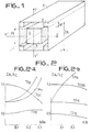
- FIGS. 2a and 2b The operation of the waveguide, object of the invention, is as follows taking into account FIGS. 2a and 2b in which FIG. 2a comprises a system of axes whose ordinates are graduated in standard cut-off frequency or ratio of dimension of the guide, according to FIG. 1, at the cut-off wavelength of this same guide, the normalized cut-off frequency being noted and whose abscissae are graduated in relation to the dimension on the side of the step W to the same dimension 2a of the waveguide.
- FIG. 2a represents the variations in the cutoff frequencies of the main propagation modes such as the TE 11 , TM 11, TE 201 and TE 10 modes. In the same way, FIG.
- FIG. 2b represents, on a system of axes, respectively on the ordinate, the normalized cut-off frequencies of the waveguide, the ordinate axis being graduated in value of the ratio where 2a represents the dimension of the side of the square section of the waveguide, according to FIG. 1, and ⁇ c the corresponding cut-off wavelength, as a function of the ratio of the dimension of the central conducting core of square section of side 2k related to this same dimension of the square section waveguide and side 2a.
- FIG. 2b represents the different standardized cut-off frequencies for the main modes such as TM 11 , TE 201 , TE 11 , and TE 10 .
- FIG. 2a and 2b respectively show that, in the case of the square guide comprising the only steps within each dihedral angle formed by two consecutive sides of the square section, the TM 11 mode limits the bandwidth as long as the ratio remains less than 0.22, the TE 201 mode becoming substantially the first parasitic mode for higher values of this ratio.
- FIG. 2b shows that, in the case of the square section guide comprising a central core of also square section, the only higher order mode limiting the bandwidth is the TE 11 mode whose cut-off frequency depends little on the report According to the ivention, the simultaneous use of the propagation characteristics of the guide alone comprising the steps, as shown in FIG.
- the bandwidth of the guide thus produced is a function of the ratios W and K , geometrical parameters of the guide according to the invention. For a determined K value, there is an optimal W ratio for which the bandwidth is maximum.
- the value of the bandwidth BW obtained by the implementation of a waveguide according to the invention as shown in FIG. 1, is given in the following table, as a function of the values of the ratios K and W. aa
- Figures 3a and 3b show for different values of the ratio k the variation of the normalized cut-off frequency , ratio of the half-dimension of the square section waveguide to the cut-off wavelength of the guide, as a function of the ratio W , dimension of the side of the section of the square step related to this same half-dimension a of the waveguide section.
- the waveguide according to the invention makes it possible to obtain a higher bandwidth than that of the guides hitherto used to solve similar problems.
- the bandwidth of the guide according to the invention, a function of the ratios k and w reaches a value of 66% when these aa ratios have the respective values 0.5 and 0.26.
- the waveguide, object of the invention further comprises a plurality of spacers 4 of dielectric material. These spacers keep the central conductive core in position.
- the waveguide according to the invention comprises, inside the guide, a foam of dielectric material 5 allowing the central conductive core to be held in position. Any embodiment in which a support system for the central conducting core is used does not depart from the scope of the present invention.
- Fc (TE 10 ) 5.588 GHz
- Fc (TE 11 ) 11.300 GHz
- the problem of finding the aa cutoff frequencies of the waveguide modes comes down to solving the two-dimensional Helmholtz equation in the cross section. of the guide. Two methods can preferably be used.
- a first method allows a polynomial calculation of the field.
- a second finite element method allows a longer but more expensive process to obtain more precise calculations.
- a double-band wideband waveguide has thus been described which can be used in particular in any microwave circuit and in particular in broadband microwave connection circuits.
Landscapes
- Waveguide Switches, Polarizers, And Phase Shifters (AREA)
- Waveguide Aerials (AREA)
Description
La présente invention est relative aux guides d'ondes hyperfréquences à large bande, permettant la propagation dans des conditions identiques de fréquence de coupure et d'impédance de deux ondes électromagnétiques de polarisation, ou direction du champ électrique, orthogonales.The present invention relates to broadband microwave waveguides, allowing propagation under identical conditions of cutoff frequency and impedance of two electromagnetic waves of polarization, or direction of the electric field, orthogonal.
Dans les guides d'ondes à large bande, c'est-à-dire les guides d'ondes utilisés sur une plage de fréquences supérieure à la bande passante normale du guide d'onde, l'apparation de modes de propagation parasites, notamment lors d'une utilisation de ces guides d'ondes dans une bande passante sensiblement supérieure à 30% de la fréquence moyenne du guide d'onde, perturbe dangereusement le fonctionnement de ce dernier. En effet, dans un guide d'onde homogène, il existe une double infinité dénombrable de modes susceptibles de se propager: les modes dits modes TE et TM, respectivement transversaux électriques et transversaux magnétiques. Chaque mode de propagation possède une fréquence de coupure en dessous de laquelle la propagation s'effectue avec atténuation. Le domaine d'utilisation d'un guide d'onde ou bande passante est la plage de fréquences qui sépare la fréquence de coupure la plus basse, dite du mode fondamental, de la fréquence de coupure suivante, dite du premier mode d'ordre supérieur. Dans cet intervalle, le seul mode de propagation possible est celui du mode fondamental.In broadband waveguides, that is to say the waveguides used over a frequency range greater than the normal passband of the waveguide, the appearance of parasitic propagation modes, in particular when these waveguides are used in a bandwidth substantially greater than 30% of the average frequency of the waveguide, dangerously disturbs the operation of the latter. Indeed, in a homogeneous waveguide, there is a countable double infinity of modes liable to propagate: the modes known as TE and TM modes, electric transverse and magnetic transverse respectively. Each propagation mode has a cutoff frequency below which the propagation takes place with attenuation. The field of use of a waveguide or bandwidth is the frequency range which separates the lowest cutoff frequency, called the fundamental mode, from the next cutoff frequency, called the first higher order mode . In this interval, the only possible mode of propagation is that of the fundamental mode.
La bande passante est définie par le rapport:![]()
![]()
La contrainte de la double polarisation impose à la section transversale du guide d'admettre l'axe longitudinal du guide d'onde comme axe de symétrie d'ordre 4n où n est un entier quelconque ≥ 1, une symétrie d'ordre 4n par rapport à cet axe longitudinal étant une symétrie telle qu'une rotation autour de ce même axe de la section du guide d'onde d'un angle de![]()
![]()
Cependant, un mode déterminé ne se propage que s'il existe les conditions nécessaires à son excitation, le mode TE20, mode dissymétrique, n'apparaissant pas dans un guide d'onde où sont maintenues des conditions de symétrie de propagation radioélectrique, même au-delà de la fréquence de coupure du mode TE20. Par contre, un coudage du guide, propre à créer une dissymétrie, provoque l'apparition du mode TEzo. Un guide n'est donc utilisable, en dehors de sa bande passante, que dans des conditions très particulières de symétrie mécanique et/ou radioélectrique.However, a determined mode propagates only if there are the conditions necessary for its excitation, the TE 20 mode, asymmetrical mode, not appearing in a waveguide where radio propagation symmetry conditions are maintained, even beyond the TE 20 cutoff frequency. On the other hand, a bending of the guide, capable of creating an asymmetry, causes the appearance of the TE zo mode. A guide can therefore only be used, outside of its bandwidth, under very specific conditions of mechanical and / or radio symmetry.
Différentes solutions ont été proposées, en vue de l'augmentation de la bande passante, sans provoquer l'apparition de modes parasites d'ordre supérieur. Une solution consiste à ajouter à la structure du guide d'onde un redan, connu sous le vocable anglosaxon de »ridge«, n'a pas permis, dans le cas des guides de section circulaire ou carrée, d'obtenir un accroissement de bande passante aussi important que dans le cas du guide de section rectangulaire. De tels résultats ont été publiés; notamment dans le cadre des études effectuées par M. H. Chen, G. N. Tsandou- las et F. G. Willwerth, intitulées »Modal Cha- racteristics of quadruple-ridged circular and square waveguides«, publiées dans la revue IEEE-Trans Microwave Theory Tech Vol MTT 22, pages 801 à 804, Août 1974.Different solutions have been proposed, with a view to increasing the bandwidth, without causing the appearance of parasitic modes of higher order. One solution consists in adding to the structure of the waveguide a step, known under the term Anglosaxon of "ridge", did not make it possible, in the case of the guides of circular or square section, to obtain an increase in band as important as in the case of the rectangular section guide. Such results have been published; notably in the framework of studies carried out by MH Chen, GN Tsandoulas and FG Willwerth, entitled “Modal Characteristics of quadruple-ridged circular and square waveguides“, published in the journal IEEE-Trans Microwave Theory Tech Vol MTT 22, pages 801 to 804, August 1974.
Une autre solution, consistant à introduire des redans carrés dans les angles dièdres formés par les côtés d'un guide d'onde de section carrée, a permis d'obtenir une bande passante de 38% ce type de guide d'onde pouvant être utilisé sur un octave de bande, avec seulement un mode parasite TE20 désigné comme modeTE201 obtenu lorsque la dégénérescence entre le mode TE20 et le mode TE02d'un guide carré est levée par l'adjonction de redans. Une telle solution a été publiée par H. J. Stalzer, M. D. Greenman et F. G. Willwerth dans une publication intitulée »Modes of crossed rectangular waveguide« dans la revue IEEE-Trans Ant Propag - AP, March 1976.Another solution, consisting in introducing square steps in the dihedral angles formed by the sides of a square section waveguide, made it possible to obtain a bandwidth of 38% this type of waveguide which can be used. on a band octave, with only one TE 20 parasitic mode designated as TE mode 201 obtained when the degeneration between TE 20 mode and TE 02 mode of a square guide is lifted by the addition of steps. One such solution was published by HJ Stalzer, MD Greenman and FG Willwerth in a publication entitled "Modes of crossed rectangular waveguide" in the journal IEEE-Trans Ant Propag - AP, March 1976.
Dans ces différentes solutions, l'adjonction de redans à des guides d'ondes de section carrée, octogonale, ou circulaire n'a jamais permis de dépasser une bande passante de 40%In these different solutions, the addition of steps to square, octagonal or circular section waveguides has never made it possible to exceed a bandwidth of 40%
Une autre solution consiste à adjoindre à des guides d'ondes de section rectangulaire un noyau central conducteur. Une telle solution a été décrite, notamment, dans l'article de L. Gruner, intitulé »Higher order modes in rectangularwave- guides« et pulié dans la revue IEEE-Trans microwave theory tech (Corresp.) Vol MTT 15, pages 483 à 485, August 1967.Another solution consists in adding to the waveguides of rectangular section a central conductive core. Such a solution has been described, in particular, in the article by L. Gruner, entitled "Higher order modes in rectangularwave-guides" and published in the review IEEE-Trans microwave theory tech (Corresp.) Vol MTT 15, pages 483 to 485, August 1967.
On connait aussi par la FR-A-2 116 441 un guide d'onde à large bande et double polarisation dans lequel la section efficace est cruciforme. Ce guide d'onde est constitué par un conducteur creux, de section rectangulaire ou carrée, sur la face interne duquel sont disposés quatre coins situés sur les bissectrices des axes principaux de propagation dans le but d'obtenir la transmission de l'onde injectée avec un amortissement particu- tièrement faible.Also known from FR-A-2 116 441 is a broadband, double polarization waveguide in which the cross section is cruciform. This waveguide consists of a hollow conductor, of rectangular or square section, on the internal face of which are arranged four corners situated on the bisectors of the main axes of propagation in order to obtain the transmission of the wave injected with particularly low depreciation.
La présente invention a pour but d'accroitre notablement la bande passante d'un guide d'onde en vue d'obtenir des bandes passantes supérieures à 60%The present invention aims to significantly increase the bandwidth of a waveguide in order to obtain bandwidths greater than 60%
L'objet de l'invention est un guide d'onde à large bande et à double polarisation constitué d'un conducteur creux de section polygonale ayant par rapport à son centre de symétrie, une symétrie d'ordre 4n, dans laquelle n est un entier, et deux axes principaux de propagation, mutuellement orthogonaux, la face interne de ce conducteur creux est munie de quatre redans dont les plans de symétrie longitudinaux sont situés selon les bissectrices des axes principaux de propagation et ce guide d'onde comporte un noyau central conducteur de forme polygonale, la section de ce noyau central et celle du conducteur creux étant homothétiques par rapport au centre de symétrie.The subject of the invention is a wideband, double polarization waveguide consisting of a hollow conductor of polygonal section having with respect to its center of symmetry, a symmetry of order 4n, in which n is an integer, and two main axes of propagation, mutually orthogonal, the internal face of this hollow conductor is provided four notches whose longitudinal planes of symmetry are located along the bisectors of the main axes of propagation and this waveguide comprises a central conductive core of polygonal shape, the section of this central core and that of the hollow conductor being homothetic with respect to the center of symmetry.
Le guide d'onde selon l'invention peut être utilisé dans tout système de connexion ou circuit hyperfréquence utilisé dans la transmission de signaux à large bande de fréquence. L'invention sera mieux comprise à l'aide de la description et des dessins ci-après où les cotes et proportions relatives des différents éléments n'ont pas été respectées, afin d'assurer une meilleure compréhension de l'ensemble et dans lesquels,
- - la figure 1 représente un guide d'onde à large bande à double polarisation, selon l'invention;
- - les figures 2a, 2b représentent respectivement la variation des fréquences de coupure, d'une part pour un guide d'onde à redans diagonaux seul, et d'autre part, pour un guide d'onde à noyau central conducteur seul;
- - les figures 3a, 3b représentent la variation de la fréquence de coupure du guide d'onde, selon le mode de réalisation de l'invention, tel que représenté figure 1, en fonction des paramètres géométriques du mode de réalisation considéré;
- - les figures 4a et 4b représentent une vue de face d'une coupe, selon un plan orthogonal à l'axe longitudinal du guide d'onde du mode de réalisation de la figure 1, selon deux variantes de réalisation particulières.
- - Figure 1 shows a broadband waveguide with double polarization, according to the invention;
- - Figures 2a, 2b respectively show the variation of the cut-off frequencies, on the one hand for a waveguide with diagonal steps only, and on the other hand, for a waveguide with a conductive central core only;
- - Figures 3a, 3b show the variation of the cutoff frequency of the waveguide, according to the embodiment of the invention, as shown in Figure 1, depending on the geometric parameters of the embodiment considered;
- - Figures 4a and 4b show a front view of a section along a plane orthogonal to the longitudinal axis of the waveguide of the embodiment of Figure 1, according to two particular embodiments.
Selon la figure 1, le guide d'onde à large bande à double polarisation, objet de l'invention, comprend un conductur creux de section polygonale 1 présentant, par rapport à un centre de symétrie C, une symétrie d'ordre 4n où n est un entier quelconque. Le guide d'onde, selon l'invention, contient à l'intérieur du conducteur creux de section polygonale une pluralité de redans conducteurs 2, dont la section détermine, avec la section polygonale, une section de propagation du guide d'onde. Chacun des redans 2 est disposé sur la face interne des côtés du conducteur creux, selon une symétrie d'ordre 4 par rapport au centre de symétrie C. Le plan de symétrie longitudinal de chacun des redans est orienté, dans la section de propagation du guide d'onde, dans la direction des bissectrices des axes principaux du guide d'onde. Sur la figure 1, les axes principaux du guide d'onde sont représentés par les axes X'X, et Y'Y, leur orientation correspond respectivement à la direction des champs électriques des modes de propagation TElQ et TEoi, pour le guide d'onde considéré. Sur la figure 1, le plan de symétrie longitudinal de chaque redan n'a pas été représenté afin de ne pas surcharger la figure. Le guide d'onde, selon l'invention, comporte, d'autre part, à l'intérieur du conducteur creux de section polygonale, un noyau centrai conducteur 3, dont la section présente par rapport au centre de symétrie C une même symétrie d'ordre 4n, les sections du noyau central conducteur et du conducteur creux de section polygonale étant homothétiques par rapport à ce centre de symétrie C.According to FIG. 1, the wide-band double polarization waveguide, object of the invention, comprises a hollow conductor of
Selon la figure 1, le conducteur creux de section polygonale a une section carrée de côté 2a. Cette section présente, par rapport au centre de symétrie C, une symétrie d'ordre 4. Le conducteur creux comporte, à l'intérieur de chaque angle dièdre formé par deux côtés consécutifs de la section carrée, un redan conducteur 2 de section également carrée du côté W. Les quatre redans disposés dans la section du conducteur creux, à l'extrémité des diagonales de cette section, déterminent, avec la section carrée du conducteur creux, une section de propagation du guide d'onde présentant, par rapport à ce même centre de symétrie C, une symétrie d'ordre 4. Selon l'invention, le conducteur creux de section polygonale comporte, d'autre part, un noyau central conducteur 3 dont la section carrée de côté 2k présente, par rapport à ce même centre de symétrie C, une même symétrie d'ordre 4. Ainsi, les diagonales de la section carrée du conducteur creux 1 et les diagonales de la section du noyau central conducteur sont confondues.According to Figure 1, the hollow conductor of polygonal section has a
Le fonctionnement du guide d'onde, objet de l'invention, est le suivant compte tenu des figures 2a et 2b dans lesquelles la figure 2a comporte un système d'axes dont les ordonnées sont graduées en fréquence de coupure normalisée ou rapport de la dimension du guide, selon la figure 1, à la longueur d'onde de coupure de ce même guide, la fréquence de coupure normalisée étant notée
![]()
![]()
![]()


![]()
![]()
![]()
Les figures 3a et 3b représentent pour différentes valeurs du rapport k la variation de la fré- a quence de coupure normalisée ![]()
![]()
Selon la figure 4a, le guide d'onde, objet de l'invention, comporte en outre une pluralité d'entretoises 4 de matériau diélectrique. Ces entretoises permettent de maintenir en position le noyau central conducteur. Selon une variante de réalisation représentée figure 4b, le guide d'onde selon l'invention comporte à l'intérieur du guide une mousse de matériau diélectrique 5 permettant de maintenir en position le noyau central conducteur. Tout mode de réalisation dans lequel un système de maintien du noyau central conducteur est utilisé ne sort pas du cadre de la présente invention. A titre d'exemple, les fréquences de coupure principales d'un guide, pour lesquelles les dimensions resoectives étaient![]()
![]()
Une première méthode, la méthode de Ray- leigh-Ritz, permet un calcul polynômial du champ. Une deuxième méthode par éléments finis, permet par un processus plus long mais plus coûteux d'obtenir des calculs plus précis. On a ainsi décrit un guide d'onde à large bande à double polarisation utilisable en particulier dans tout circuit hyperfréquence et notamment dans les circuits de connexion hyperfréquences à large bande.A first method, the Rayleigh-Ritz method, allows a polynomial calculation of the field. A second finite element method allows a longer but more expensive process to obtain more precise calculations. A double-band wideband waveguide has thus been described which can be used in particular in any microwave circuit and in particular in broadband microwave connection circuits.
Claims (6)
Applications Claiming Priority (2)
| Application Number | Priority Date | Filing Date | Title |
|---|---|---|---|
| FR7909493A FR2454188A1 (en) | 1979-04-13 | 1979-04-13 | DOUBLE POLARIZATION BROADBAND WAVEGUIDE AND MICROWAVE CIRCUIT HAVING SUCH A WAVEGUIDE |
| FR7909493 | 1979-04-13 |
Publications (2)
| Publication Number | Publication Date |
|---|---|
| EP0018261A1 EP0018261A1 (en) | 1980-10-29 |
| EP0018261B1 true EP0018261B1 (en) | 1984-03-14 |
Family
ID=9224337
Family Applications (1)
| Application Number | Title | Priority Date | Filing Date |
|---|---|---|---|
| EP80400448A Expired EP0018261B1 (en) | 1979-04-13 | 1980-04-03 | Wide-band waveguide with double polarisation |
Country Status (4)
| Country | Link |
|---|---|
| US (1) | US4303900A (en) |
| EP (1) | EP0018261B1 (en) |
| DE (1) | DE3066913D1 (en) |
| FR (1) | FR2454188A1 (en) |
Families Citing this family (5)
| Publication number | Priority date | Publication date | Assignee | Title |
|---|---|---|---|---|
| US4523160A (en) * | 1983-05-02 | 1985-06-11 | George Ploussios | Waveguide polarizer having conductive and dielectric loading slabs to alter polarization of waves |
| US4904966A (en) * | 1987-09-24 | 1990-02-27 | The United States Of America As Represented By The Secretary Of The Navy | Suspended substrate elliptic rat-race coupler |
| US7061445B2 (en) * | 2003-08-26 | 2006-06-13 | Andrew Corporation | Multiband/multichannel wireless feeder approach |
| WO2006019776A2 (en) * | 2004-07-14 | 2006-02-23 | William Marsh Rice University | A method for coupling terahertz pulses into a coaxial waveguide |
| US7531803B2 (en) * | 2006-07-14 | 2009-05-12 | William Marsh Rice University | Method and system for transmitting terahertz pulses |
Family Cites Families (8)
| Publication number | Priority date | Publication date | Assignee | Title |
|---|---|---|---|---|
| DE1013338B (en) * | 1952-12-27 | 1957-08-08 | Pintsch Electro Gmbh | Inner conductor, especially for VHF lines, with enlarged electrical length |
| US3002163A (en) * | 1960-01-08 | 1961-09-26 | Polytechnic Inst Brooklyn | Mode coupler for circular waveguides |
| US3150333A (en) * | 1960-02-01 | 1964-09-22 | Airtron Division Of Litton Pre | Coupling orthogonal polarizations in a common square waveguide with modes in individual waveguides |
| US3569870A (en) * | 1968-08-21 | 1971-03-09 | Rca Corp | Feed system |
| DE2055443C3 (en) * | 1970-11-11 | 1982-02-25 | Licentia Patent-Verwaltungs-Gmbh, 6000 Frankfurt | Polarization converter for microwaves |
| FR2116441B1 (en) * | 1970-12-03 | 1974-08-19 | Licentia Gmbh | |
| US4035598A (en) * | 1974-10-22 | 1977-07-12 | Johannes Menschner Maschinenfabrik Gmbh & Co. Kg. | Apparatus for thermally treating polymeric workpieces with microwave energy |
| FR2294554A1 (en) * | 1974-12-10 | 1976-07-09 | Thomson Csf | Rectangular coaxial line section for RF oscillator - U-shaped closed by cover plate and enclosing inner conductor with diode |
-
1979
- 1979-04-13 FR FR7909493A patent/FR2454188A1/en active Granted
-
1980
- 1980-04-03 DE DE8080400448T patent/DE3066913D1/en not_active Expired
- 1980-04-03 EP EP80400448A patent/EP0018261B1/en not_active Expired
- 1980-04-10 US US06/139,123 patent/US4303900A/en not_active Expired - Lifetime
Also Published As
| Publication number | Publication date |
|---|---|
| FR2454188B1 (en) | 1983-03-11 |
| FR2454188A1 (en) | 1980-11-07 |
| EP0018261A1 (en) | 1980-10-29 |
| US4303900A (en) | 1981-12-01 |
| DE3066913D1 (en) | 1984-04-19 |
Similar Documents
| Publication | Publication Date | Title |
|---|---|---|
| EP3547450B1 (en) | Radiating element with circular polarisation implementing a resonance in a fabry-perot cavity | |
| EP0426972B1 (en) | Flat antenna | |
| EP0285503B1 (en) | Filter with distributed constant elements associating two kinds of coupling arrangements | |
| EP0047203B1 (en) | Microwave filter with a dielectric resonator tunable over a large bandwidth | |
| EP2195877B1 (en) | Omt type broadband multiband transmission-reception coupler-separator for rf frequency telecommuncations antennas | |
| EP3726642B1 (en) | Polarising screen with wideband polarising radiofrequency cell(s) | |
| EP0108003B1 (en) | Double strip line resonators and filter using such resonators | |
| EP0018261B1 (en) | Wide-band waveguide with double polarisation | |
| FR2889358A1 (en) | Microwave bandstop filter for filtering assembly, has waveguide section with transversal section having variation whose amplitude is such that minimal spacing between two walls is comprised between specified range of average spacing | |
| EP2658032B1 (en) | Corrugated horn antenna | |
| EP0467818B1 (en) | Transition element between electromagnetic waveguides, especially between a circular waveguide and a coaxial waveguide | |
| FR2582449A1 (en) | BROADBAND POLARIZATION DIPLEXER DEVICE AND ANTENNA ASSOCIATED WITH RADAR OR COUNTERMEASURE DEVICE COMPRISING SUCH A DEVICE | |
| EP0075498B1 (en) | Cavity filter with coupling between non-adjacent cavities | |
| EP0296929B1 (en) | Balanced microwave transmission line with two coplanar conductors | |
| Saleh | An adjustable quasi-optical bandpass filter-Part II: Practical considerations | |
| CA2031076A1 (en) | Micro-wage guide band-stop filter | |
| EP0064458A1 (en) | High selectivity rectangular waveguide bandpass filter | |
| FR2487587A1 (en) | HYPERFREQUENCY BANDWIDTH FILTER REALIZED IN A WAVEGUIDE | |
| EP0520919B1 (en) | Filtering device for electromagnetic waves in a waveguide with symmetry around the rotational axis, and inserted pieces of rectangular waveguide | |
| WO2024047573A1 (en) | Six-port orthomode junction | |
| EP1067617B1 (en) | Bandpass filter | |
| FR3134659A1 (en) | Device for controlling RF electromagnetic beams according to their frequency band and manufacturing method | |
| FR2652203A1 (en) | UHF filter in waveguide, with flaps | |
| EP0921587A1 (en) | Microwave filter with a steep upper edge | |
| FR2711844A1 (en) | Radome with correction by grids |
Legal Events
| Date | Code | Title | Description |
|---|---|---|---|
| PUAI | Public reference made under article 153(3) epc to a published international application that has entered the european phase |
Free format text: ORIGINAL CODE: 0009012 |
|
| AK | Designated contracting states |
Designated state(s): DE GB IT NL SE |
|
| 17P | Request for examination filed |
Effective date: 19801112 |
|
| ITF | It: translation for a ep patent filed | ||
| GRAA | (expected) grant |
Free format text: ORIGINAL CODE: 0009210 |
|
| AK | Designated contracting states |
Designated state(s): DE GB IT NL SE |
|
| REF | Corresponds to: |
Ref document number: 3066913 Country of ref document: DE Date of ref document: 19840419 |
|
| PLBE | No opposition filed within time limit |
Free format text: ORIGINAL CODE: 0009261 |
|
| STAA | Information on the status of an ep patent application or granted ep patent |
Free format text: STATUS: NO OPPOSITION FILED WITHIN TIME LIMIT |
|
| 26N | No opposition filed | ||
| PGFP | Annual fee paid to national office [announced via postgrant information from national office to epo] |
Ref country code: GB Payment date: 19900331 Year of fee payment: 11 |
|
| PGFP | Annual fee paid to national office [announced via postgrant information from national office to epo] |
Ref country code: DE Payment date: 19900404 Year of fee payment: 11 |
|
| PGFP | Annual fee paid to national office [announced via postgrant information from national office to epo] |
Ref country code: SE Payment date: 19900405 Year of fee payment: 11 |
|
| ITTA | It: last paid annual fee | ||
| PGFP | Annual fee paid to national office [announced via postgrant information from national office to epo] |
Ref country code: NL Payment date: 19900430 Year of fee payment: 11 |
|
| PG25 | Lapsed in a contracting state [announced via postgrant information from national office to epo] |
Ref country code: GB Effective date: 19910403 |
|
| PG25 | Lapsed in a contracting state [announced via postgrant information from national office to epo] |
Ref country code: SE Effective date: 19910404 |
|
| PG25 | Lapsed in a contracting state [announced via postgrant information from national office to epo] |
Ref country code: NL Effective date: 19911101 |
|
| GBPC | Gb: european patent ceased through non-payment of renewal fee | ||
| NLV4 | Nl: lapsed or anulled due to non-payment of the annual fee | ||
| PG25 | Lapsed in a contracting state [announced via postgrant information from national office to epo] |
Ref country code: DE Effective date: 19920201 |
|
| EUG | Se: european patent has lapsed |
Ref document number: 80400448.9 Effective date: 19911108 |