EP0075313B1 - Agricultural device - Google Patents
Agricultural device Download PDFInfo
- Publication number
- EP0075313B1 EP0075313B1 EP82108695A EP82108695A EP0075313B1 EP 0075313 B1 EP0075313 B1 EP 0075313B1 EP 82108695 A EP82108695 A EP 82108695A EP 82108695 A EP82108695 A EP 82108695A EP 0075313 B1 EP0075313 B1 EP 0075313B1
- Authority
- EP
- European Patent Office
- Prior art keywords
- agricultural apparatus
- reservoir
- carrier frame
- cultivation material
- microprocessor
- Prior art date
- Legal status (The legal status is an assumption and is not a legal conclusion. Google has not performed a legal analysis and makes no representation as to the accuracy of the status listed.)
- Expired
Links
Images


Classifications
-
- A—HUMAN NECESSITIES
- A01—AGRICULTURE; FORESTRY; ANIMAL HUSBANDRY; HUNTING; TRAPPING; FISHING
- A01C—PLANTING; SOWING; FERTILISING
- A01C7/00—Sowing
- A01C7/08—Broadcast seeders; Seeders depositing seeds in rows
- A01C7/10—Devices for adjusting the seed-box ; Regulation of machines for depositing quantities at intervals
- A01C7/102—Regulating or controlling the seed rate
-
- A—HUMAN NECESSITIES
- A01—AGRICULTURE; FORESTRY; ANIMAL HUSBANDRY; HUNTING; TRAPPING; FISHING
- A01C—PLANTING; SOWING; FERTILISING
- A01C15/00—Fertiliser distributors
- A01C15/005—Undercarriages, tanks, hoppers, stirrers specially adapted for seeders or fertiliser distributors
- A01C15/006—Hoppers
Definitions
- the invention relates to an agricultural device for spreading liquid, powdered or granular cultivated material, with a storage container mounted on a support frame for receiving the cultivated material.
- fertilizers, spraying and spraying agents for weed and pest control machines and devices that are particularly suitable for the respective purpose are used, which carry the material to be spread in a storage container and which are carried out with the help of a tractor, tractor or tractor working agricultural land.
- the cultivation material is driven either by the machine's wheels or by a drive shaft, usually gimbal-mounted, driven by the tractor.
- seeders in which the grain is housed in the seed box carried.
- fertilizer spreaders the powdery to granular material is also carried in a storage container that is filled from above.
- Pesticides and weed control agents are usually carried in liquid form and sprayed or sprayed onto the land or the crop plants via variously operating nozzles.
- the known devices for spreading a certain amount of cultivated material per unit area work mechanically or hydromechanically, in which, depending on the driving speed via metering wheels or throwing vanes for solid substances, or for certain nozzle settings or pressurization for liquids, in advance using tables or should be achieved based on empirical values.
- the preselected settings often lead to incorrect results because the setpoint of the application rate is influenced by unpredictable or undetectable influencing factors. This includes e.g. B.
- the dosing set can only be achieved by constantly checking the amount applied in relation to the area already worked on and continuously adjusting the setting. So far, the volume of the seed box contents has been measured either mechanically by floats which are supposed to rest on the grain surface, optically by sight glasses or electrically by infrared or light barriers or contact switches. All of these methods work insufficiently, because swimmers dig themselves easily into the grain, especially when shaken, contact switches work poorly with light seeds that tend to form bridges, while the other measuring devices quickly become dusty and therefore unusable.
- the object of the invention is therefore to provide the agricultural device of the type mentioned, in which the output of the cultivated material can be metered by detecting the weight of the storage container and thus the weight of the cultivated material carried.
- a cantilever beam is attached to the support frame, on which the storage container is suspended by means of an all-round movable holding member with simultaneous guidance in a vertical direction, and in that a sensor between the storage container and is used to measure the weight of the storage container Support frame is arranged.
- a cantilever beam is fastened to the support frame, on which the storage container is supported from below by means of a holding member with simultaneous guidance in the vertical direction, and a sensor is arranged between the storage container and the supporting frame for detecting the weight of the storage container.
- the storage container is supported outside of the plane of its center of gravity via at least one connecting piece rigidly connecting it to the supporting frame, and at least one strain gauge is arranged on the connecting piece for detecting the weight of the storage container.
- a pneumatic or hydropneumatic spring system is provided between the support frame and the storage container and the spring system as a sensor for detecting the weight of the storage container and in the spring system a pressure sensor serving as a measuring sensor for detecting the weight of the storage container, the spring system having at least two hydropneumatic springs and each Hydropneumatic spring has a piston-cylinder unit and a pressure vessel, which is divided by an elastic partition into a gas pressure section and a hydraulic section, the hydraulic section being connected to the piston-cylinder unit via a line and the gas pressure section being connected to the pressure sensor via a throttle.
- All of the embodiments are based on the common principle of determining the object of the storage container by measuring the weight of the entire container, acceleration forces when starting and braking as well as forces when the device is inclined cannot largely form sources of interference for the measurement.
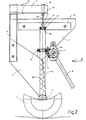
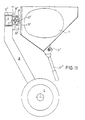
- FIGs 1 and 2 the invention is shown using the example of a sowing or drilling machine, in which the machine frame is supported on an axis 1 and driven with the wheels 2, for example with the aid of a tractor, a tractor or a tractor, over the usable area to be ordered can be.
- a machine frame 3 is attached to the axis 1 on both sides, and a vertical support strut 4 is fastened to this, which supports a horizontal bar in the form of a cantilever or torsion beam 5.
- a vertical support column 6 is also attached, on which the storage container 7, in the example shown the box for receiving the seed grain, is guided.
- the metering wheels 10 sit on the drive shaft 11 and, when the machine is not in use, can be terminated from the supply of seeds by means of the slide 12, which engage in the outlet shafts of the storage container 7.
- the storage container 7 is suspended completely freely, so that there are no fixed, in particular rigid connections to the machine frame 3, 4; it is guided smoothly on both sides in the support columns 6 in the vertical direction and with am Storage tanks attached below ball bearings 13 and above with the help of an approximately in the middle of the storage container 7 attached guide ring 14 which can slide up and down on a pin 15 formed at the upper end of the support column 6.
- the upper end face 14a of the support column 6 serves as a stop for the vertical movement of the storage container 7 in the event of impacts acting on the seeder.
- Both the guide ring 14 and a bolt 17 are fastened to a cross rail 16 which is attached in the upper region to the side faces of the storage container 7.
- a holding tab 18 with a locating bolt 19 is attached above the storage container 7 in the plane of its center of gravity, to which a holding member 20 in the form of an all-round movable support cable is attached, which is anchored at its lower end to the bolt 17 .
- Strain gauges 21 are bonded to the upper and lower surfaces of the two cantilever beams 5, which are connected as resistors in the branches of measuring bridges in such a way that their resistance changes in the deflection of the cantilever beam 5 add up due to the load suspended thereon with respect to the bridge output voltage, because in the Bridge adjacent resistors on opposite surfaces and opposed resistors on the same side of the measuring body.
- the strain gauges 21 therefore have the function of a sensor for the weight of the storage container 7 acting on the holding member 20.
- Damping an RC element then an amplifier with feedback, a balancer for the two measuring bridges and an operational amplifier with an adjusting device for setting the subsequent display instrument to zero when the storage container is empty.
- the display instrument which is expediently arranged in the field of vision of the tractor drive and can be calibrated in kg, kg or liters, shows “zero”.
- the influence of the weight of the drive device for the metering mechanism, which is an integral part of the sowing or spraying machines, on the freely suspended storage container and thus also on the measuring device is expediently avoided by using force transmission means which do not exert any mechanical and weight-distorting forces on the storage container exercise such.
- strain gauges can also be attached to the side surfaces of the cantilever 5 in order to compensate for disturbances, such as strains of the supporting structure due to temperature influences or disturbances due to acceleration forces. So that the suspension cable 20 is tensioned in every operating state, in particular when the container is slightly filled or in the event of impacts, the container 7 is preloaded with the aid of tension springs 22 by a downward force component. In order to prevent damage to the strain gauges in the event of excessive dynamic force and also to prevent their linear resistance range from being exceeded, the vertical movement of the storage container 7 is limited by the stops 14, 14a described in more detail above.
- an elastic spring guide is provided instead of the rigid guidance of the storage container through the support column 6 described above.
- an inclined pair of tension springs 23 are attached to each machine side, which are anchored with their lower ends to horizontal cross members 24 attached to the machine frame, and with their upper ends to the lower side parts of the storage container 7.
- Another tension spring pair 25 running diagonally to the center of the machine is anchored on the one hand to a holder 26 fastened in the middle of the axis 1 and on the other hand also to the two lower outer sides of the storage container 7.
- These pairs of springs 23 and 25 fix the reservoir 7 at its lower region in its desired position, while in the upper region it is held in its working position by the holding members 20 which can move on all sides and which engage in the focal plane.
- the holding members 20 which can move on all sides and which engage in the focal plane.
- the downward preloading of the container 7 is exerted by the tension spring pairs 23 and 25, so that the holding member 20 is always under tension and the seed located in the storage container as a tensile force on the cantilever beams 5 and thus also on the strain gauges 21 as electrical sensors transmits.
- the storage container 7 is suspended on all two cantilever beams 5 with the aid of rubber spring elements 27, which are also known under the name of vibrating metal.
- a tab 28 is attached to the two lateral cross rails 16, with which the rubber spring element 27 is fixedly connected.
- the elastic fixing of the container 7, not shown in this figure, can optionally be carried out in the manner shown in FIG. 4.
- the storage container 7 is supported in its focal plane either in the middle or on its lower outer edges on rubber spring elements 27, which are seated on the cantilever beams 51 laid downwards.
- the yieldingly movable guidance of the storage container is in this embodiment by a Ge provided at the upper end of the support strut 4 Steer 29 causes that together with the rubber spring element 27 allows an up and down movement about the hinge axis 29.
- the rubber spring elements also act as a damping device, so that the vibrations or shocks which may occur during operation do not trigger any undesirable vibrations of the storage container 7.
- Fig. 7 the electrical measuring circuit is shown using a simplified block diagram.
- the strain gauges fastened on the cantilever beam 5 are connected as sensors in the form of variable resistors 21 in a corresponding manner in the branches of a DC measuring bridge 30.
- the strain gauges attached to the top and bottom of the cantilever 5 are arranged in such a way that when the cantilever 5 is loaded they change their resistance values in the sense that they add up their effect in the bridge. So that they do not cancel each other out with regard to their effect in the bridge, adjacent resistances in the bridge when the cantilever beam 5 is loaded must be stressed in the opposite manner and opposite ones in the bridge in the same direction. So you can also all the stretching forces that act like a slide on the top and bottom, such as. B.
- torsion bars can also be used, with a lever arm on which the container hangs or on which it stands.
- the strain gauges must then be glued in spiral lines with a 45 ° slope. strips with opposite signs of action must sit on ascending or descending spiral lines.
- draw beams or compression beams can also be used instead of cantilever beams.
- resistors acting in opposite directions in the bridge must be glued once in the longitudinal direction and once in the transverse direction.
- the dynamic portion of the forces acting on the sensor from the movements of the storage container 7 is greater than the static portion. Therefore, the voltage derived from the measured variable is first filtered or attenuated in an RC element as a low-pass filter 31 and equalized in it as in the subsequent individual amplifier 32.
- the measured values from the two measuring bridges 30 are adapted in the subsequent balancer 33 and fed to an analog or digital indicator 35 via the operational amplifier 34.
- the display of the measuring instrument 35 which can be calibrated, for example, in kg, kg or in liters, can be adjusted with a balancing resistor in such a way that it shows a measurement variable “zero” when the storage container 7 is empty.
- the measuring bridge 30 and the other circuit parts are supplied from the on-board electrical system of the tractor.
- the working voltage of 12 V usually present there is stabilized in a known manner to, for example, 5 V using electrical or electronic switching elements.
- permanent magnets 130 are evenly distributed on the circumference, which generate electrical impulses in the reed switches 200, 300 when the impellers 12 rotate.
- These impulses and the electrical voltages resulting from the strain gauges 21 are converted into an electrical quantity in a metering control circuit to be described below, with which a direct current control valve 100 is acted upon.
- the energy supply for the hydraulic metering drive comes from the hydraulic pump of the tractor.
- the energy supply runs via the electrically actuated direct current control valve 100 to an oil motor 110 and from there back through the return line 80 to the hydraulic pump of the tractor .
- the oil motor 110 drives the metering drive, which consists, for example, of metering cam wheels 10 arranged on a drive shaft 11 in a known manner.
- the metering wheels 10 can be closed by slides 12 which engage in the discharge pipes 8 of the storage container 7.
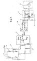
- Fig. 8 shows the circuit of the metering control circuit.
- a microprocessor 400 is entered on its input side via the input station 120, the target value of the metered amount of the cultivated material, for example using a keyboard.
- voltage pulses are sent to further inputs of the microprocessor 400 depending on the rotational speed of the impellers.
- the arrangement on both sides allows the different rotational speeds of the impellers to be compensated for when cornering. Via the weighing system 30 already described for FIG.
- the individual amplifier 32, the comparator 33 and the operational amplifier 34 is also present on the microprocessor 400 with a voltage signal analogous to the respective amount of cultivated material in the storage container.
- the reed switches 200 and 300 receive pulses at certain intervals.
- the weight loss for the cultivated agricultural area is given in a simple manner for the given size of the impellers and given machine working width from the number of pulses from the reed switches 200, 300 per interval.
- the quotient thus determined in the microprocessor 400 from the quantity of cultivated material applied and the cultivated agricultural area is compared in the microprocessor 400 with the entered target value.
- Differences in this comparison are converted on the output side of the microprocessor 400 into an electrical signal, which acts in a regulating manner on the direct current control valve 100 and is fed back from there to the input of the microprocessor 400.
- This conversion is stored in an action curve in the microprocessor 400 and is continuously corrected during the application of the cultivated material on the basis of the actually occurring number of impulses - dosage quantity strength - value pairs and approximated to the target value.
- action curves are stored in the microprocessor, which can be selected via the input station 120 at the beginning of the application of the crop according to their suitability for the particular crop to be applied. A test run can also be selected before work on the stand.
- Different current intensities on the DC control valve 100 are determined during certain time intervals by metering the residual amounts in the reservoir after each test time interval, and thus the applied difference in quantity is calculated.
- the test value pairs are saved to improve the impact curve. If there are deviations of a certain amount between the target value and the actual value of the cultivated amount applied during work, a warning display appears.
- the action curve is designed for a specific driving speed, ie for a specific pulse frequency from the reed switches 200 and 300. Frequency deviations are converted by the microprocessor 400 into proportional changes in the operating speed of the metering mechanism.
- the energy supply for the hydraulic metering drive comes from the hydraulic pump of the tractor and runs via the inlet 70 and a flow distributor 90, which stabilizes the fluctuating pressure of the pump at different tractor engine speeds, via the electrically actuated direct current control valve 100 and an oil motor 110 and back through the Backflow 80 into the tractor storage tank.
- the oil motor 110 drives the metering mechanism, which consists of metering wheels 10 on the metering wheel drive shaft 11.
- the power supply for the electrical or electronic control is branched off from the tractor's electrical system.
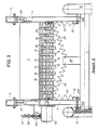
- the reference numeral 7 denotes a seed box accessible from above with a conventional V-shaped cross-sectional shape for receiving the seed 11, which, for. B. is part of a seed drill.
- This seed drill can either be attached to a tractor via a so-called lifting device (not shown) or can have its own chassis.
- a stirrer shaft 12 "for the seed 11" extends in the longitudinal direction through the seed box 7 and is driven by a gear (not shown) at one end of the seed box.
- This gear also drives a shaft 13 "on which 7 seed wheels 16" are fastened at a lateral distance from one another, in each case opposite a seed tube 14 "and an opening 15" in the bottom of the seed box, which have cams on their circumference and the seeds 11 "in feed metered amounts to the seed tubes 14 ".
- the seed wheels 16 “thus form, as it were, locks for the seed 11".
- a number of such seed tubes 14" extend downwards, over which the seed 11 "
- the openings 15 "in the bottom of the seed box 7 can be closed by individual slides 18" which can be actuated via a common operating rod 19 ".
- the slides 18 are slidably mounted in a common clip-shaped holder 20".
- the seed box 7 is supported on supports 21 on two hydropneumatic springs 22 ".
- the supports 21" are by means of piston-shaped extensions 24 "in guide tubes 25" guided vertically.
- the lower end of each support 21 is supported directly on an upwardly projecting extension of the piston 26".
- the pistons 26 ′′ can be biased upwards by the pressure of a hydraulic fluid.
- each of the two cylinders 27 ′′ is connected via a hydraulic line 28 ′′ to a hydraulic section 29 ′′ of a pressure container 30 ′′.
- Another hydraulic line device 31 "connects the hydraulic lines 28" to one another, and this hydraulic line 31 contains a connection, schematically indicated at 32 ", to the hydraulic system of the tractor pulling the drill.
- a pressure container 30" is assigned to each of the two cylinders 27 ", and each pressure vessel 30 "is divided by an elastic partition 33" into the already mentioned hydraulic section 29 "and a gas pressure section 34".
- the gas pressure sections 34 ′′ of the two pressure vessels 30 ′′ are connected to one another by a pipe 50 ′′ having a relatively narrow internal cross section.
- a manometer 52 ′′ is connected to the pipe 50 ′′ via a further pipe 51 ′′.
- a throttle 53 is installed in the pipeline 51" in front of the manometer 52 ".
- the scale of the manometer 52" is calibrated accordingly for measuring the weight of the seed 11 "in the seed box 7.
- the respective weight of the seed box contents can be read continuously during the filling process and subsequently during the work of the seed drill.
- the throttle 53" upstream of the manometer 52 dampens sudden pressure increases and decreases e.g. due to vibrations of the seed drill or due to acceleration or deceleration forces during work.
- the weight of the applied amount of grains can advantageously be continuously checked and the operator can determine relatively easily whether the actual values lie in the target range and the desired high sowing accuracy and thus an optimal plant density can be achieved.
- the seed outflow from the seed box 7 can be regulated, either by appropriate actuation of the slide 18" and / or change in the speed of the shaft 13 "with the seed wheels 16".
Description
Die Erfindung betrifft eine landwirtschaftliche Vorrichtung zum Ausbringen von flüssigem, pulverförmigem oder körnigem Kultiviergut, mit einem an einem Traggestell gelagerten Vorratsbehälter zur Aufnahme des Kultiviergutes.The invention relates to an agricultural device for spreading liquid, powdered or granular cultivated material, with a storage container mounted on a support frame for receiving the cultivated material.
Zur Ausbringung von Saatgut, Düngemitteln, Sprüh- und Spritzmitteln zur Unkraut- und Schädlingsbekämpfung werden für den jeweiligen Zweck besonders geeignete Maschinen und Geräte verwendet, die das auszubringende Material in einem Vorratsbehälter mitführen und die mit Hilfe eines Traktors, Schleppers oder einer Zugmaschine über die zu bearbeitende landwirtschaftliche Nutzfläche gefahren werden. Der Antrieb für die Ausbringung des Kultiviergutes erfolgt dabei entweder über die Laufräder der Maschine oder über eine vom Traktor angetriebene, meist kardanisch aufgehängte Antriebswelle. Als Beispiele dienen Sämaschinen, bei denen das Getreide im mitgeführten Saatkasten untergebracht ist. Bei Düngerstreuern wird das pulverförmige bis körnige Material ebenfalls in einem Vorratsbehälter mitgeführt, der von oben gefüllt wird. Schädlings- und Unkrautbekämpfungsmittel werden meist in flüssiger Form mitgeführt und über verschiedenartig arbeitende Düsen auf das Land bzw. die Kulturpflanzen gespritzt oder gesprüht. Dabei ist es zur Erzielung eines optimalen Ernteergebnisses oder einer optimalen Qualität von besonderer Bedeutung, daß die auszubringenden Mittel, z. B. wegen ihrer Kosten, wegen ihrer Wirkung oder ihres Bodenbesatzes (Verstockung) wegen der Art des Bodens, in der günstigsten Menge pro Flächeneinheit ausgebracht werden. Deshalb ist eine laufende Kontrolle des Gewichtes oder des In- . halts des Vorratsbehälters während der Landarbeit von eminenter Bedeutung. Kann sich der Landwirt laufend, beispielsweise mit Hilfe eine Anzeigeinstrumentes, über den jeweiligen Vorrat des Kultiviergutes im Behälter informieren, so ist es ihm auch möglich, eine Kontrolle über die ausgebrachte Menge auszuüben und darüber hinaus in Relation zu der bereits bearbeiteten Fläche die spezifische Ausbringungsdichte abzuschätzen oder zu berechnen. Die Anzeige des Gewichts im Behälter erlaubt deshalb eine Beurteilung darüber, ob die gewünschte und zu Beginn der Feldarbeit an der Maschine eingestellte Mengenverteilung über die Bodenfläche, d. h. die erforderliche Konzentration, erreicht worden ist.For the spreading of seeds, fertilizers, spraying and spraying agents for weed and pest control, machines and devices that are particularly suitable for the respective purpose are used, which carry the material to be spread in a storage container and which are carried out with the help of a tractor, tractor or tractor working agricultural land. The cultivation material is driven either by the machine's wheels or by a drive shaft, usually gimbal-mounted, driven by the tractor. Examples are seeders in which the grain is housed in the seed box carried. With fertilizer spreaders, the powdery to granular material is also carried in a storage container that is filled from above. Pesticides and weed control agents are usually carried in liquid form and sprayed or sprayed onto the land or the crop plants via variously operating nozzles. It is of particular importance to achieve an optimal harvest result or an optimal quality that the means to be applied, for. B. because of their cost, because of their effect or their stocking (blockage) because of the type of soil, in the cheapest amount per unit area. That is why an ongoing check of the weight or the in. holding the reservoir during farm work of eminent importance. If the farmer can continuously obtain information, for example with the help of a display instrument, about the respective supply of the cultivated material in the container, he can also exercise control over the amount applied and also estimate the specific output density in relation to the area already worked or to calculate. The display of the weight in the container therefore allows an assessment to be made as to whether the desired quantity distribution over the floor area and set at the start of the field work on the machine, i. H. the required concentration has been reached.
Die bekannten Vorrichtungen zur Ausbringung einer bestimmten Menge des Kultiviergutes pro Flächeneinheit arbeiten auf mechanischem oder hydromechanischem Wege, bei denen in Abhängigkeit von der Fahrgeschwindigkeit über Dosierräder oder Wurfschaufeln bei festen Stoffen, bzw. bei bestimmten Düseneinstellungen oder Druckbeaufschlagungen bei Flüssigkeiten, die vorab mit Hilfe von Tabellen oder aufgrund von Erfahrungswerten eingestellten Werte erzielt werden sollen. Die vorgewählten Einstellungen führen jedoch häufig zu falschen Ergebnissen, weil durch nicht vorhersehbare oder nicht erfaßbare Einflußfaktoren der Sollwert der Ausbringungsmenge beeinflußt wird. Hierzu gehört z. B. der Schlupf der Laufräder auf dem Boden, Erschütterungen, die während der Fahrt oder der Arbeit des Kultiviergerätes auf den Dosiermechanismus einwirken, wechselnde Gleitfähigkeit von gekörntem Saatgut, das während der Aussaat unterschiedlich gebeizt wird und deshalb mehr oder weniger aneinander haftet, und im Vorratsbehälter Brücken bildet, vor allem bei leichtem Saatgut und bei Düngemitteln durch Feuchtigkeit und dadurch hervorgerufenen Verklebungen. wechselnde Viskosität der Spritzflüssigkeit, Veränderungen der zu bearbeitenden Bodenfläche hinsichtlich ihrer physikalischen Eigenschaft und ihrer Formationen und ggf. auch Witterungseinflüsse. Wegen dieser Zufalleinflüsse genügt es nicht, die Drehzahl der Dosiereinrichtung in konstanter Abhängigkeit von der Drehzahl der Maschinenlaufräder zu steuern bzw. den Druck für das auszubringende Spritzmittel zu regulieren. Da wie oben dargelegt, die einzelnen Einflußfaktoren nicht erfaßt werden können, wird die eingestellte Dosierung nur durch die ständige Kontrolle der ausgebrachten Menge in bezug auf die bereits bearbeitete Fläche und einer laufenden Korrektur der Einstellung erreicht werden können. Bisher hat man das Volumen des Saatkasteninhalts entweder mechanisch durch Schwimmer, welche auf der Getreideoberfläche aufliegen sollen, optisch durch Schaugläser oder elektrisch durch Infrarot- oder Lichtschranken oder auch Kontaktschalter gemessen. Alle diese Verfahren arbeiten ungenügend, denn Schwimmer graben sich, insbesondere bei Erschütterungen, leicht in das Getreide ein, Kontaktschalter arbeiten mangelhaft bei leichten und zur Brückenbildung neigenden Saatgütern, während die übrigen Meßeinrichtungen schnell verstauben und dadurch unbrauchbar werden.The known devices for spreading a certain amount of cultivated material per unit area work mechanically or hydromechanically, in which, depending on the driving speed via metering wheels or throwing vanes for solid substances, or for certain nozzle settings or pressurization for liquids, in advance using tables or should be achieved based on empirical values. However, the preselected settings often lead to incorrect results because the setpoint of the application rate is influenced by unpredictable or undetectable influencing factors. This includes e.g. B. the slippage of the wheels on the ground, vibrations that act on the metering mechanism while driving or working the cultivator, changing gliding ability of granular seeds that are treated differently during sowing and therefore more or less stick to each other, and in the storage container Builds bridges, especially with light seeds and fertilizers due to moisture and the resulting sticking. changing viscosity of the spray liquid, changes in the surface to be treated with regard to its physical properties and its formations and possibly also weather influences. Because of these random influences, it is not sufficient to control the speed of the metering device in constant dependence on the speed of the machine impellers or to regulate the pressure for the spraying agent to be applied. Since, as explained above, the individual influencing factors cannot be recorded, the dosing set can only be achieved by constantly checking the amount applied in relation to the area already worked on and continuously adjusting the setting. So far, the volume of the seed box contents has been measured either mechanically by floats which are supposed to rest on the grain surface, optically by sight glasses or electrically by infrared or light barriers or contact switches. All of these methods work insufficiently, because swimmers dig themselves easily into the grain, especially when shaken, contact switches work poorly with light seeds that tend to form bridges, while the other measuring devices quickly become dusty and therefore unusable.
Zusammenfassend kann daher festgestellt werden, daß mit keiner der vorstehenden Methoden eine exakte quantitative Erfassung der jeweiligen Saatgutmenge im Saatkasten einer Sämaschine möglich ist.In summary, it can therefore be stated that none of the above methods enables an exact quantitative recording of the respective seed quantity in the seed box of a seeder.
In der landtechnischen Praxis wird meist noch nach umständlichen Methoden gearbeitet. Bei Sämaschinen wird z. B. nach einer Saattabelle zunächst eine Grobeinstellung der Dosiereinrichtung vorgenommen. Weil aber das Tausendkorngewicht des Saatgutes unterschiedlich ist, muß der Dosiermechanismus vor der eigentlichen Feldarbeit im Stand der Maschine abgedreht werden, um eine Probemenge des Saatgutes zu erhalten, die dann auf einer separaten Waage abgewogen werden muß. Nach Prüfung des Ergebnisses wird dann die Einstellung so oft nachgestellt, bis das gewünschte Ergebnis erreicht ist. Bei der darauffolgenden Feldarbeit wird aber dieses mühsam erzielte Ergebnis aus den oben angeführten Gründen verfälscht. Die derzeitige Praxis ist deshalb ebenso umständlich wie ungenau.In agricultural engineering practice, laborious methods are usually still used. In seeder z. B. first made a rough setting of the metering device according to a seed table. However, because the thousand-grain weight of the seeds is different, the metering mechanism must be turned off before the actual field work in the state of the machine in order to obtain a sample amount of the seeds, which must then be weighed on a separate balance. After checking the result, the setting is readjusted until the desired result is achieved. In the subsequent field work, however, this laborious result is obtained from the above falsified reasons. Current practice is therefore as cumbersome as it is imprecise.
Aufgabe der Erfindung ist es deshalb, die landwirtschaftliche Vorrichtung der eingangs genannten Art zu schaffen, bei der durch Erfassen des Gewichtes des Vorratsbehälters und damit des Gewichtes des mitgeführten Kultiviergutes das Ausbringen des Kultiviergutes dosierbar ist.The object of the invention is therefore to provide the agricultural device of the type mentioned, in which the output of the cultivated material can be metered by detecting the weight of the storage container and thus the weight of the cultivated material carried.
Diese Aufgabe wird bei einem ersten Ausführungsbeispiel dadurch gelöst, daß an dem Traggestell ein Kragträger befestigt ist, an dem der Vorratsbehälter mittels eines allseits beweglichen Haltegliedes unter gleichzeitiger Führung in senkrechter Richtung aufgehängt ist, und daß zum Erfassen des Gewichtes des Vorratsbehälters ein Meßfühler zwischen Vorratsbehälter und Traggestell angeordnet ist.This object is achieved in a first embodiment in that a cantilever beam is attached to the support frame, on which the storage container is suspended by means of an all-round movable holding member with simultaneous guidance in a vertical direction, and in that a sensor between the storage container and is used to measure the weight of the storage container Support frame is arranged.
Nach einem zweiten Ausführungsbeispiel ist an dem Traggestell ein Kragträger befestigt, auf dem von unten her der Vorratsbehälter mittels eines Haltegliedes unter gleichzeitiger Führung in senkrechter Richtung abgestützt ist, und ist zum Erfassen des Gewichtes des Vorratsbehälters ein Meßfühler zwischen Vorratsbehälter und Traggestell angeordnet.According to a second embodiment, a cantilever beam is fastened to the support frame, on which the storage container is supported from below by means of a holding member with simultaneous guidance in the vertical direction, and a sensor is arranged between the storage container and the supporting frame for detecting the weight of the storage container.
Nach einem dritten Ausführungsbeispiel ist der Vorratsbehälter über mindestens ein ihn starr mit dem Traggestell verbindenden Verbindungsstück außerhalb der Ebene seines Schwerpunktes abgestützt und ist zum Erfassen des Gewichtes des Vorratsbehälters mindestens ein Dehnungsmeßstreifen am Verbindungsstück angeordnet.According to a third exemplary embodiment, the storage container is supported outside of the plane of its center of gravity via at least one connecting piece rigidly connecting it to the supporting frame, and at least one strain gauge is arranged on the connecting piece for detecting the weight of the storage container.
Nach einem vierten Ausführungsbeispiel ist ein pneumatisches oder hydropneumatisches Federsystem zwischen Traggestell und Vorratsbehälter und dem Federsystem als Meßfühler zur Erfassung des Gewichtes des Vorratsbehälters und im Federsystem ein als Meßfühler zur Erfassung des Gewichtes des Vorratsbehälters dienender Druckfühler vorgesehen, wobei das Federsystem wenigstens zwei hydropneumatische Federn und jede hydropneumatische Feder eine Kolbenzylindereinheit und einen Druckbehälter aufweist, der durch eine elastische Trennwand in einen Gasdruckabschnitt und einen Hydraulikabschnitt unterteilt ist, wobei der Hydraulikabschnitt über eine Leitung mit der Kolbenzylindereinheit und der Gasdruckabschnitt über eine Drossel mit dem Druckfühler verbunden ist.According to a fourth exemplary embodiment, a pneumatic or hydropneumatic spring system is provided between the support frame and the storage container and the spring system as a sensor for detecting the weight of the storage container and in the spring system a pressure sensor serving as a measuring sensor for detecting the weight of the storage container, the spring system having at least two hydropneumatic springs and each Hydropneumatic spring has a piston-cylinder unit and a pressure vessel, which is divided by an elastic partition into a gas pressure section and a hydraulic section, the hydraulic section being connected to the piston-cylinder unit via a line and the gas pressure section being connected to the pressure sensor via a throttle.
Alle Ausführungsformen beruhen auf dem gemeinsamen Prinzip, den Gegenstand des Vorratsbehälters durch eine Gewichtsmessung des ganzen Behälters zu bestimmen, wobei Beschleunigungskräfte beim Anfahren und Bremsen sowie Kräfte bei Schräglagen der Vorrichtung für die Messung weitgehend keine Störungsquellen bilden können.All of the embodiments are based on the common principle of determining the object of the storage container by measuring the weight of the entire container, acceleration forces when starting and braking as well as forces when the device is inclined cannot largely form sources of interference for the measurement.
Bevorzugte weitere Ausbildungen der Ausführungsbeispiele sind in den abhängigen Ansprüchen angegeben.Preferred further developments of the exemplary embodiments are specified in the dependent claims.
Weitere Einzelheiten der Erfindung und ihrer Vorteile sind im folgenden anhand der Ausführungsbeispiele näher beschrieben und in den Zeichnungen dargestellt. In der Zeichnung zeigen :
Figur 1 zeigt die Erfindung anhand einer Sämaschine in der Ansicht von hinten in schematischer Darstellung,Figur 2 zeigt die wesentlichen Teile der Sämaschine nach Fig. 1 in der Seitenansicht,Figur 3 zeigt die Sämaschine nach Fig. 1 in der Rückansicht, jedoch mit einer anders ausgebildeten Lagerung des Vorratsbehälters,Figur 4 zeigt die Maschine nach Fig. 3 in der Seitenansicht,Figur 5 zeigt den Vorratsbehälter in Seitenansicht mit Aufhängung an einem Gummifederelement,Figur 6 zeigt eine Seitenansicht des Vorratsbehälters, der auf einem Gummifederelement aufgestützt ist,Figur 7 zeigt in einem Blockschaltbild die elektrische Meßanordnung mit einer Brückenschaltung,Figur 8 zeigt die Sthaltung einer Dosier-Steuervorrichtung,Figur 9 zeigt eine schematische Querschnittsansichteines Saatkastens einer Drillmaschine, abgestützt auf hydropneumatischen Federn, welche Teile einer Meßvorrichtung bilden,Figur 10 zeigt eine schematische Rückansicht der Anordnung nach Fig.9, jedoch ohne Saatrohre und Fahrgestell,Figur 11 zeigt einen Querschnitt durch die Aufhängung eines Vorratsbehälters an einem landwirtschaftlichen Gerät undFigur 12 zeigt drei verschiedene schematische Darstellungen eines an Torsionsstäben aufgehängten Vorratsbehälters.
- FIG. 1 shows the invention using a seed drill in a view from the rear in a schematic illustration,
- FIG. 2 shows the essential parts of the seed drill according to FIG. 1 in a side view,
- FIG. 3 shows the seed drill according to FIG. 1 in a rear view, but with a differently designed storage of the storage container,
- FIG. 4 shows the machine according to FIG. 3 in a side view,
- FIG. 5 shows the storage container in a side view with suspension on a rubber spring element,
- FIG. 6 shows a side view of the storage container, which is supported on a rubber spring element,
- FIG. 7 shows the electrical measuring arrangement with a bridge circuit in a block diagram,
- FIG. 8 shows the maintenance of a dosing control device,
- Figure 9 shows a schematic cross-sectional view of a seed box of a seed drill supported on hydropneumatic springs which form part of a measuring device,
- FIG. 10 shows a schematic rear view of the arrangement according to FIG. 9, but without seed tubes and chassis,
- FIG. 11 shows a cross section through the suspension of a storage container on an agricultural implement and
- FIG. 12 shows three different schematic representations of a storage container suspended on torsion bars.
In den Figuren 1 und 2 ist die Erfindung am Beispiel einer Sä- oder Drillmaschine dargestellt, bei der das Maschinengestell auf einer Achse 1 abgestützt ist und mit den Laufrädern 2 beispielsweise mit Hilfe eines Traktors, einer Zugmaschine oder eines Schleppers über die zu bestellende Nutzfläche gefahren werden kann. An der Achse 1 ist an beiden Seiten ein Maschinenrahmen 3, und an diesem jeweils eine senkrechte Tragstrebe 4 befestigt, die einen waagerechten Balken in Form eines Krag- oder Torsionsträgers 5 trägt. An beiden Seiten der Achse 1 ist weiterhin je eine senkrechte Tragsäule 6 befestigt, an der der Vorratsbehälter 7, im gezeigten Beispiel der Kasten zur Aufnahme des Saatgetreides, geführt ist. An den Vorratsbehälter 7 der Sämaschine schließen sich die üblichen Ausbringrohre 8 an, die an Haltewellen 9 gelagert sind und denen über die Dosierräder 10 die gewünschte Menge des Saatgutes zugeführt wird. Die Dosierräder 10 sitzen auf der Antriebswelle 11 und können bei Nichtgebrauch der Maschine von der Versorgung mit Saatgut mit Hilfe der Schieber 12 abgeschlossen werden, die in die Auslaufschächte des Vorratsbehälters 7 eingreifen. Der Vorratsbehälter 7 ist vollkommen frei aufgehängt, so daß es keine festen, insbesondere starren Verbindungen mit dem Maschinengestell 3, 4 gibt; er ist an beiden Seiten in den Tragsäulen 6 in senkrechter Richtung leichtgängig geführt und zwar mit am Vorratsbehälter unten befestigten Kugellagern 13 und oben mit Hilfe eines etwa in der Mitte des Vorratsbehälters 7 befestigten Führungsringes 14, der an einem am oberen Ende der Tragsäule 6 ausgebildeten Zapfen 15 auf und ab gleiten kann. Dabei dient die obere Stirnfläche 14a der Tragsäule 6 als Anschlag für die Vertikalbewegung des Vorratsbehälters 7 bei auf die Sämaschine einwirkenden Stößen. Sowohl der Führungsring 14 als auch ein Bolzen 17 sind an einer Querschiene 16 befestigt, die im oberen Bereich an den Seitenflächen des Vorratsbehälters 7 angebracht ist. Am freien Ende des Kragträgers 5 ist über dem Vorratsbehälter 7 in der Ebene seines Schwerpunktes eine Haltelasche 18 mit einem Aufnahmebolzen 19 angebracht, an dem ein Halteglied 20 in Form eines allseitig beweglichen Tragseiles befestigt ist, das mit seinem unteren Ende an dem Bolzen 17 verankert ist. An den Ober- und Unterflächen der beiden Kragträger 5 sind Dehnungsmeßstreifen 21 geklebt, die als Widerstände derart in die Zweige von Meßbrücken geschaltet sind, daß sich ihre Widerstandsveränderungen bei der Durchbiegung des Kragträgers 5 aufgrund der daran aufgehängten Last bezüglich der Brückenausgangsspannung addieren, weil in der Brücke benachbarte Widerstände auf gegenüberliegenden Flächen und gegenübergeschaltete Widerstände auf derselben Meßkörperseite aufgeklebt werden. Die Dehnungsmeßstreifen 21 haben also die Funktion eines Meßwertgebers für das an dem Halteglied 20 angreifende Gewicht des Vorratsbehälters 7. Die elektrische Ausgangsgröße der 'Meßbrücke wird nach der in Fig. 7 gezeigten Blockschaltung wegen der im Bereich oft auftretenden Erschütterungen und Stöße zunächst zur Glättung bzw. Dämpfung einem RC-Glied, dann einem Verstärker mit Rückkopplung, einem Abgleicher für die beiden Meßbrücken und einem Operationsverstärker mit einer Justiervorrichtung für die Einstellung des nachfolgenden Anzeigeinstrumentes auf « Null bei leerem Vorratsbehälter, zugeführt. Bei leerem Vorratsbehälter 7 zeigt das Anzeigeinstrument, das zweckmäßigerweise im Blickfeld des Traktorfahres angeordnet ist und in kg, kp oder Liter geeicht sein kann, « Null » an. Der Einfluß des Gewichts der Antriebsvorrichtung für den Dosiermechanismus, der wesentlicher Bestandteil der Sä- oder Sprühmaschinen ist, auf den frei aufgehängten Vorratsbehälter und damit auch auf die Meßvorrichtung wird zweckmäßigerweise dadurch vermieden, daß Kraftübertragungsmittel verwendet werden, die keine mechanischen und gewichtsverfälschenden Kräfte auf den Vorratsbehälter ausüben, wie z. B. Hydraulikantrieb mit flexiblen Zuleitungen, biegsame Wellen, Kardan-oder Gelenkgetriebe. Auch an den Seitenflächen des Kragträgers 5 können erforderlichenfalls Dehnungsmeßstreifen befestigt sein, um Störgrößen zu kompensieren, wie Dehnungen der Tragkonstruktion aufgrund von Temperatureinflüssen oder Störgrößen infolge von Fahrtbeschleunigungskräften. Damit das Tragseil 20 in jedem Betriebszustand gespannt ist, insbesondere bei geringer Füllung des Behälters oder bei Stößen, wird der Behälter 7 mit Hilfe von Zugfedern 22 durch eine nach unten gerichtete Kraftkomponente vorbelastet. Um bei zu hoher dynamischer Krafteinwirkung auf die Dehnungsmeßstreifen ihre Beschädigung zu verhindern und auch um eine Überschreitung ihres linearen Widerstandsbereiches zu verhindern, ist die senkrechte Bewegung des Vorratsbehälters 7 durch die oben näher beschriebenen Anschläge 14, 14a begrenzt.In Figures 1 and 2, the invention is shown using the example of a sowing or drilling machine, in which the machine frame is supported on an
Gemäß den Figuren 3 und 4, in denen der besseren Übersichtlichkeit wegen Teile mit gleicher Funktion wie in den Figuren 1 und 2 mit denselben Bezugszahlen versehen sind, ist anstelle der starren Führung des Vorratsbehälters durch die oben geschilderte Tragsäule 6 eine elastische Federführung vorgesehen. Zu diesem Zwecke sind an jeder Maschinenseite je ein schräg verlaufendes Paar Zugfedern 23 angebracht, die mit ihrem unteren Ende an waagerechten, am Maschinengestell befestigten Traversen 24, und mit ihren oberen Enden an den unteren Seitenteilen des Vorratsbehälters 7 verankert sind. Ein weiteres diagonal zur Maschinenmitte verlaufendes Zugfederpaar 25 ist einerseits an einem in der Mitte der Achse 1 befestigten Halter 26 und andererseits ebenfalls an den beiden unteren Außenseiten des Vorratsbehälters 7 verankert. Diese Federpaare 23 und 25 fixieren den Vorratsbehälter 7 an seinem unteren Bereich in seiner Sollage, während er im oberen Bereich durch die allseitig beweglichen Halteglieder 20, die in der Schwerpunktebene angreifen, in seiner Arbeitslage gehalten wird. Auch bei dieser Ausführungsform besteht keine feste und starre Verbindung zwischen dem Vorratsbehälter 7 und dem Maschinentrag- und -gestellteilen. Auch hier wird die nach unten gerichtete Vorbelastung des Behälters 7 durch die Zugfederpaare 23 und 25 ausgeübt, so daß das Halteglied 20 stets unter Zugspannung steht und das im Vorratsbehälter befindliche Saatgut als Zugkraft auf die Kragträger 5 und damit auch auf die Dehnungsmeßstreifen 21 als elektrische Meßwertgeber überträgt.According to FIGS. 3 and 4, in which, for better clarity, parts with the same function as in FIGS. 1 and 2 are provided with the same reference numbers, an elastic spring guide is provided instead of the rigid guidance of the storage container through the
Gemäß Figur 5 ist der Vorratsbehälter 7 mit Hilfe von Gummifederelementen 27, die auch unter dem Namen Schwingmetall bekannt sind, an den beiden Kragträgern 5 allseitig beweglich aufgehängt. Zu diesem Zwecke sind an den beiden seitlichen Querschienen 16 eine Lasche 28 befestigt, mit der das Gummifederelement 27 fest verbunden ist. Die in dieser Figur nicht dargestellte elastische Fixierung des Behälters 7 kann ggf. nach der in Fig. 4 gezeigten Art vorgenommen werden.According to FIG. 5, the
Gemäß Figur 6 stützt sich der Vorratsbehälter 7 in seiner Schwerpunktebene entweder in der Mitte oder an seinen unteren Außenkanten auf Gummifederelemente 27 ab, die auf den nach unten verlegten Kragträgern 51 aufsitzt. Die nachgebend bewegliche Führung des Vorratsbehälters wird in diesem Ausführungsbeispiel durch ein am oberen Ende der Tragstrebe 4 vorgesehenes Gelenk 29 bewirkt, das zusammen mit dem Gummifederelement 27 eine Auf- und Abbewegung um die Gelenkachse 29 ermöglicht. Die Gummifederelemente wirken auch als Dämpfungseinrichtung, damit die beim Betrieb möglicherweise auftretenden Erschütterungen oder Stöße keine unerwünschten Schwingungen des Vorratsbehälters 7 auslösen.According to FIG. 6, the
In Fig. 7 ist die elektrische Meßschaltung anhand eines vereinfachten Blockschaltbildes dargestellt. Die auf dem Kragträger 5 befestigten Dehnungsmeßstreifen sind als Meßwertgeber in Form von veränderbaren Widerständen 21 in sinngemäßer Weise in die Zweige einer Gleichstrommeßbrücke 30 geschaltet. Dabei sind die auf der Ober- und Unterseite des Kragträgers 5 angebrachten Dehnungsmeßstreifen derart angeordnet, daß sie bei Belastung des Kragträgers 5 ihre Widerstandswerte in dem Sinne verändern, daß sie ihre Wirkung in der Brücke summieren. Damit sie sich bezüglich ihrer Wirkung in der Brücke nicht aufheben, müssen in der Brücke benachbarte Widerstände bei Belastung des Kragträgers 5, in entgegengesetzter Weise beansprucht werden und in der Brücke gegenüberliegende gleichsinnig. So können sie auch alle Dehnungskräfte, die gleiohmäßig auf die Ober-und Unterseite einwirken, wie z. B. Querbeschleunigungen bei Kurvenfahrten, Seitenstöße durch Abrutschen am Hang oder auch Veränderungen durch Wärmedehnung, vollständig kompensieren. Derartige Krafteinwirkungen verformen die Ober- und Unterseite des .Kragträgers gleichmäßig und heben sich daher im Spannungsgefälle innerhalb der Meßbrücke auf, so daß sie die Gewichtsanzeige nicht verfälschen können. Das gleiche gilt für die Brems- und Anfahrbeschleunigung, deren Kräfte die Vorder- und Rückseite der Meßkörper stauchen bzw., dehnen, jedoch die Ober- und Unterseite nicht meßrelevant beeinflussen. Möglich sind auch andere Klebemuster der Dehnungsmeßstreifen auf dem Kragbalkenmeßkörper, z. B. auf den Flanken, wobei Nachbarwiderstände in der Brücke einmal am oberen und einmal am unteren Rand aufgeklebt werden, wegen der notwendigen entgegengesetzten Beanspruchung, und gegenübergeschaltete Widerstände einmal auf der Vorderflanke und einmal auf der Rückflanke befestigt werden, damit sie die dann entgegengesetzt wirkende Beanspruchung durch Beschleunigungen in Fahrtrichtung kompensieren. Anstelle von Kragbalken-Meßkörpern können auch Torsionsstäbe verwendet werden, mit einem Hebelarm, an dem der Behälter hängt oder auf dem er steht. Die Dehnungsmeßstreifen müssen dann in Spirallinien mit 45° Steigung aufgeklebt sein. Streifen mit entgegengesetztem Wirkungsvorzeichen müssen auf auf- bzw. absteigenden Spirallinien sitzen. Gleichfalls können anstelle von Kragbalken auch Zugbalken oder Stauchbalken verwendet werden. Hier müssen entgegengesetzt in der Brücke wirkende Widerstände einmal in Längs- und einmal in Querrichtung geklebt werden. Wegen der unvermeidbaren Kräfte durch Fahrbeschleunigung und Erschütterungen ist der dynamische Anteil der auf den Meßwertgeber einwirkenden Kräfte aus den Bewegungen des Vorratsbehälters 7 größer als der statische Anteil. Deshalb wird die aus der Meßgröße abgeleitete Spannung zunächst in einem RC-Glied als Tiefpaß 31 gefiltert bzw. gedämpft und in ihm wie in dem nachfolgenden Einzelverstärker 32 entzerrt. Die Meßwerte aus den beiden Meßbrücken 30 werden in dem anschließenden Abgleicher 33 angepaßt und über den Operationsverstärker 34 einem Analog- oder Digitalanzeiger 35 zugeführt. Mit einem Abgleichwiderstand kann die Anzeige des Meßinstrumentes 35, das beispielsweise in kg, kp oder in Liter geeicht sein kann, derart justiert werden, daß es bei leerem Vorratsbehälter 7 eine Meßgröße « Null anzeigt. Die Speisung der Meßbrücke 30 und der übrigen Schaltungsteile erfolgt aus dem Bordnetz des Traktors. Zu diesem Zwecke wird die dort üblicherweise vorliegende Arbeitsspannung von 12 V in bekannter Weise mit Hilfe von elektrischen oder elektronischen Schaltelementen auf beispielsweise 5 V stabilisiert. An der Felge eines Laufrades 12 oder an den Felgen mehrerer Laufräder 12 sind am Umfang Dauermagnete 130 gleichmäßig verteilt, die bei Drehung der Laufräder 12 in den Reedschaltern 200, 300 elektrische Impulse erzeugen. Diese Impulse und die aus den Dehnungsmeßstreifen 21 sich ergebenden elektrischen Spannungen werden in einer nachfolgend noch zu beschreibenden Dosier-Steuerschaltung in eine elektrische Größe umgesetzt, mit welcher ein Gleichstrom-Steuerventil 100 beaufschlagt wird. Die Energiezufuhr für den hydraulischen Dosierantrieb kommt aus der Hydraulikpumpe des Traktors. Über den Einlaß 70 und einen Mengenteiler 90, der den schwankenden Druck der Hydraulikpumpe bei unterschiedlichen Motordrehzahlen des Traktors ausgleicht, läuft die Energiezufuhr über das elektrisch beaufschlagte Gleichstrom-Steuerventil 100 zu einem Ölmotor 110 und von dort wieder zurück durch die Rückflußleitung 80 zur Hydraulikpumpe des Traktors. Der Ölmotor 110 treibt den Dosierantrieb an, der in bekannter Weise beispielsweise aus auf einer Antriebswelle 11 angeordneten Dosiernockenrädern 10 besteht. Die Dosierräder 10 können durch Schieber 12 abgeschlossen werden, die in die Ausbringungsrohre 8 des Vorratsbehälters 7 eingreifen.In Fig. 7 the electrical measuring circuit is shown using a simplified block diagram. The strain gauges fastened on the
Fig. 8 zeigt die Schaltung der Dosier-Steuerschaltung. Einem Mikroprozessor 400 wird auf seiner Eingangsseite über die Eingabestation 120 der Sollwert der Dosiermenge des Kultiviergutes beispielsweise über eine Tastatur eingegeben. Über die Reedschalter 200, 300 neben den beiden Laufrädern gelangen in Abhängigkeit von der Umdrehungsgeschwindigkeit der Laufräder Spannungsimpulse zu weiteren Eingängen des Mikroprozessors 400. Durch die Anordnung auf beiden Seiten können die unterschiedlichen Umdrehungsgeschwindigkeiten der Laufräder beim Kurvenfahren ausgeglichen werden. Über das bereits zu Fig.3 beschriebene Wiegesystem 30 und das diesem nachgeschaltete Filter bzw. Dämpfungsglied 31, den Einzelverstärker 32, den Abgleicher 33 und den Operationsverstärker 34 liegt am Mikroprozessor 400 außerdem ein der jeweiligen Kultiviergutmenge im Vorratsbehälter analoges Spannungssignal an. Im Mikroprozessor 400 werden in bestimmten Intervallen von den Reedschaltern 200 und 300 Impulse abgerufen. gleichzeitig die Gewichtsabnahme zur bearbeiteten landwirtschaftlichen Fläche ergibt sich bei gegebenem Umfang der Laufräder und gegebener Maschinenarbeitsbreite in einfacher Weise aus der Anzahl der Impulse aus den Reedschaltern 200, 300 pro Intervall. Der so im Mikroprozessor 400 ermittelte Quotient aus ausgebrachter Menge Kultiviergutes und bearbeiteter landwirtschaftlicher Fläche wird im Mikroprozessor 400 mit dem eingegebenen Sollwert verglichen. Unterschiede bei diesem Vergleich werden auf der Ausgangsseite des Mikroprozessors 400 in ein elektrisches Signal umgesetzt, welches auf das Gleichstrom-Steuerventil 100 regelnd einwirkt und von dort zum Eingang des Mikroprozessors 400 rückgekoppelt ist. Diese Umsetzung wird in einer Wirkungskurve im Mikroprozessor 400 gespeichert und während der Ausbringung des Kultiviergutes laufend anhand der tatsächlich auftretenden Impulszahl - Dosiermengenstärke - Wertpaare korrigiert und dem Sollwert angenähert. Im Mikroprozessor sind mehrere Wirkungskurven gespeichert, die zu Beginn der Ausbringung des Kultiviergutes entsprechend ihrer Eignung für das jeweilige, auszubringende Kultiviergut über die Eingabestation 120 angewählt werden können. Ebenso angewählt werden kann auch ein Testlauf vor der Arbeit im Stand. Dabei werden unterschiedliche Stromstärken auf dem Gleichstromsteuerventil 100 während bestimmter Zeitintervalle die Dosiermengen ermittelt, indem nach jedem Testzeitintervall die Restmenge im Vorratsbehälter über den Druckaufnahmer 30 ausgewogen und so die ausgebrachte Mengendifferenz errechnet wird. Die Testwertepaare werden zur Verbesserung der Wirkungskurve gespeichert. Bei Abweichungen über ein bestimmtes Maß zwischen dem Sollwert und dem Istwert der ausgebrachten Kultiviermenge während der Arbeit erscheint eine Warnanzeige. Die Wirkungskurve ist für eine bestimmte Fahrgeschwindigkeit, d. h. für eine bestimmte Impulsfrequenz aus den Reedschaltern 200 und 300 ausgelegt. Frequenzabweichungen werden vom Mikroprozessor 400 in proportionale Änderungen der Arbeitsgeschwindigkeit des Dosiermechanismus umgesetzt. Die Energiezufuhr für den hydraulischen Dosierantrieb kommt aus der Hydraulikpumpe des Traktors und läuft über den Einlaß 70 und einen Mengenverteiler 90, der den schwankenden Druck der Pumpe bei unterschiedlichen Traktormotordrehzahlen stabilisiert, über das elektrisch beaufschlagte Gleichstrom- Steuerventil 100 und einen Ölmotor 110 und zurück durch den Rückfluß 80 in den Traktorvorratstank. Der Ölmotor 110 treibt den Dosiermechanismus an, der aus Dosierrädern 10 auf der Dosierräderantriebswelle 11 besteht. Die Energieversorgung für die elektrische bzw. elektronische Steuerung wird aus dem Bordnetz des Traktors abgezweigt.Fig. 8 shows the circuit of the metering control circuit. A
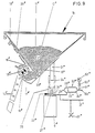
In den Figuren 9 und 10 ist mit der Bezugszahl 7 ein von oben zugänglicher Saatkasten mit üblicher V-förmiger Querschnittsform zur Aufnahme des Saatgutes 11 bezeichnet, der z. B. Bestandteil einer Drillmaschine ist. Diese Drillmaschine kann entweder über eine sogenannte Aushebevorrichtung (nicht gezeigt) an einen Schlepper angebaut sein oder ein eigenes Fahrgestell aufweisen. Durch den Saatkasten 7 erstreckt sich in Längsrichtung eine Rührwelle 12" für das Saatgut 11", die von einem nicht gezeigten Getriebe am einen Ende des Saatkastens angetrieben wird. Dieses Getriebe treibt auch eine Welle 13", auf der in seitlichem Abstand voneinander, jeweils gegenüber einem Saatrohr 14" und einer Öffnung 15" im Boden des Saatkastens 7 Säräder 16" befestigt sind, die an ihrem Umfang Nocken aufweisen und das Saatgut 11" in dosierten Mengen den Saatrohren 14" zuführen. Die Säräder 16" bilden somit gewissermaßen Schleusen für das Saatgut 11 ". Bei rotierender Welle 13" gelangt das Saatgut 11 " zwischen den Nocken jedes Särades 16" und einer Bodenklappe 17" hindurch in die Saatrohre 14". Von dem Saatkasten 7 erstrecken sich eine Reihe solcher Saatrohre 14" nach unten, über welche das Saatgut 11" in seitlich gleichmäßig beabstandeten Reihen in das Erdreich eingebracht wird. Die Öffnungen 15" im Boden des Saatkastens 7 sind durch einzelne Schieber 18" verschließbar, die über eine gemeinsame Bedienungsstange 19" betätigt werden können. Die Schieber 18" sind in einer gemeinsamen spangenförmigen Halterung 20" verschieblich gelagert.In FIGS. 9 and 10, the
Der Saatkasten 7 ist im Ausführungsbeispiel über Stützen 21 auf zwei, hydropneumatischen Federn 22" aufgelagert. Im einzelnen sind die oberen Enden der Stützen 21 " Saatkastenkonsolen 23" befestigt., die den Saatkasten 7 tragen. Ferner sind die Stützen 21 " mittels kolbenförmiger Erweiterungen 24" in Führungsrohren 25" vertikal verschieblich geführt. Die Führungsrohre 25" sind mit ihren unteren Enden an einem tragenden Teil 6" des Drillmaschinen-Fahrgestells befestigt. Die hydropneumatischen Federn 22" sind innerhalb dieser Führungsrohre 25" angeordnet, und sie weisen im einzelnen einen Kolben 26" auf, der in einem Zylinder 27" läuft, welcher gleichfalls an dem Teil 6" des Drillmaschinen-Fahrgestells befestigt ist. Wie aus den Zeichnungen ersichtlich ist, ist das untere Ende jeder Stütze 21 " unmittelbar auf einem nach oben ragenden Fortsatz des Kolbens 26" aufgelagert.In the exemplary embodiment, the
Die Kolben 26" können durch den Druck einer Hydraulikflüssigkeit nach oben vorgespannt werden. Zu diesem Zweck ist jeder der beiden Zylinder 27" über eine Hydraulikleitung 28" mit einem Hydraulikabschnitt 29" eines Druckbehälters 30" verbunden. Eine weitere Hydraulikleitung 31" verbindet die Hydraulikleitungen 28" miteinander, und diese Hydraulikleitung 31 enthält einen bei 32" schematisch angedeuteten Anschluß zum Hydrauliksystem des die Drillmaschine ziehenden Schleppers. Wie aus Fig. 10 hervorgeht, ist jedem der beiden Zylinder 27" ein Druckbehälter 30" zugeordnet, und jeder Druckbehälter 30" ist durch eine elastische Trennwand 33" in den bereits erwähnten Hydraulikabschnitt 29" und einen Gasdruckabschnitt 34" unterteilt.The
Die Gasdruckabschnitte 34" der zwei Druckbehälter 30" sind durch eine Rohleitung 50" relativ engen lichten Querschnitts untereinander verbunden. Über eine weitere Rohrleitung 51 " ist ein Manometer 52" an der Rohrleitung 50" angeschlossen. In die Rohrleitung 51 " ist vor dem Manometer 52" eines Drossel 53" eingebaut. Die Skala des Manometers 52" ist für eine Messung des Gewichts des des Saatgutes 11 " im Saatkasten 7 entsprechend geeicht.The
Bei laufendem Schlepper-Motor wird über den Anschluß 32" die Hydraulikflüssigkeit in den Rohrleitungen 31", 28" den Hydraulikabschnitten 29" und den hydropneumatischen Federn 22" mit Druck beaufschlagt, so daß die Kolben 26" in eine obere Endstellung vorgespannt sind. In diesem Zustand zeigt das Manometer 52" den Wert Null an. Wird nun in den Saatkasten 7 Saatgut 11" eingefüllt, bewirkt dessen Gewicht über die Hydraulikflüssigkeit und elastischen Trennwände 33" eine Druckerhöhung des Gases in den Gasdruckabschnitten 34" der beiden Druckbehälter 30" sowie in den Rohrleitungen 50" und 51", wodurch ein entsprechender Ausschlag des Manometers 52" erzeugt wird, der eine exakte Anzeige des Gewichts des eingefüllten Saatgutes liefert. Mit anderen Worten, auf der nach Gewichtseinheiten geeichten Skala des Manometers 52" kann das jeweilige Gewicht des Saatkasteninhalts beim Einfüllvorgang und anschließend während der Arbeit der Drillmaschine stetig abgelesen werden. Die dem Manometer 52" vorgeschaltete Drossel 53" dämpft plötzliche Druckerhöhungen und -abfälle, bedingt z. B. durch Erschütterungen der Drillmaschine oder durch Beschleunigungs-oder Verzögerungskräfte während der Arbeit.With the tractor engine running, pressure is applied via the
Auf obige Weise kann vorteilhaft das Gewicht der ausgebrachten Körnermenge stetig kontrolliert werden und der Bediener kann verhältnismäßig einfach ermitteln, ob die Ist-Werte im Soll-Bereich liegen und die angestrebte hohe Sä-Genauigkeit und damit eine optimale Pflanzendichte erreicht werden. In Abhängigkeit von der Gewichtsanzeige des Manometers 52" kann nämlich der Saatgutausfluß aus dem Saatkasten 7 geregelt werden, entweder durch entsprechende Betätigung der Schieber 18" und- /oder Änderung der Drehzahl der Welle 13" mit den Särädern 16".In the above manner, the weight of the applied amount of grains can advantageously be continuously checked and the operator can determine relatively easily whether the actual values lie in the target range and the desired high sowing accuracy and thus an optimal plant density can be achieved. Depending on the weight display of the
Fig. 11 zeigt einen Holm 4, an dessen unterem Ende ein Laufrad 2 montiert ist. Zwei derartige Holme 3 sind an ihrem den Laufrädern 2 gegenüberliegenden Ende Mittels eines Trägers 4 miteinander starr verbunden. Am als verwindungssteifes Widerlager dienenden Träger 4 sind mit Klammern 6' paarweise Halteplatten 77 befestigt, welche zwischen sich Spannfutter 15' für die drehfeste Lagerung der Enden der einzelnen, axial nebeneinander angeordneten Torsionswellen 9' aufnehmen. Damit eine sichere Lagerung der Enden der Torsionswellen 9' gegeben ist, sind die Enden der Torsionswellen 9' mit Nasen 10' ausgebildet, die vom Spannfutter 15' fest gehalten werden. Jedes Spannfutter 15' ist durch eine. Abschlußplatte 8' abgeschlossen. Von jeder Torsionswelle 9' stehen senkrecht Stege 11' weg, welche über Sockel 12' mit den Konsolen 13' des Vorratsbehälters 7 mechanisch fest verbunden sind. Die starre Aufhängung des Vorratsbehälters 7 wird noch dadurch optimiert, daß die Konsolen 13' zu dem Vorratsbehälter 7 in seinem Inneren versteifenden Spanten ausgestaltet sein können, und die Stege 11' mit den Spanten fluchten. In dieser Figur sind noch Dosierräder 3' und Ausbringungsrohre 11' angedeutet, über welche das im Vorratsbehälter 7 befindliche Kultiviergut ausgebracht wird. Der Vorratsbehälter 7 ist starr und fest am Gestell des landwirtschaftlichen Gerätes befestigt, wobei eine Reduzierung der Hebelmomente senkrecht zur Hauptzugrichtung besonders dann erreicht wird, wenn möglichst kurz gehaltene, als Stege 11' ausgebildete Verbindungsstücke in einer Ebene liegen, welche horizontal durch den Schwerpunkt des gefüllten Vorratsbehälters 7 verlaufen. Durch derartige, kurze und breit gehaltene Verbindungsstücke haben im Betrieb auftretende Querkräfte keinen Einfluß auf den Meßformkörper in Form der Torsionswellen 9' und damit auf das sich aus den Dehnungsmeßstreifen ergebenden Meßergebnis. Durch die starre, feste Befestigung des Vorratsbehälters 7 wirken auf die vorzugsweise mehrteilige Torsionswelle 9' nur senkrechte, insbesondere das Gewicht des im Vorratsbehälter 7 befindlichen Kultiviergutes versinnbildlichenden Kräfte ein, die die auf den Torsionswellen 9' befestigten Dehnungsmeßstreifen im Sinne einer Gewichtsbestimmung beeinflussen. Die Verarbeitung und Verwertung der aus den Dehnungsmeßstreifen sich ergebenden . analogen elektrischen Daten erfolgt so wie zuvor beschrieben. Der Träger 4 bildet mit den beiden seitlichen Holmen 3 baulich eine Einheit, wobei an den unteren Enden der Holme 3 die in dieser Figur nicht dargestellen Laufräder gelagert sind. Die am Träger 4 zwischen Halteplatten 77 befindlichen Spannfutter 15' sind durch Abschlußplatten 8' lokalisiert. Diese Spannfutter 15' fassen die Enden der Torsionswellen 9'. Zwischen den drehfesten Fassungen 77, 8', 15' der Torsionswellen 9' und den diesen benachbarten Stegen 11' sind auf den Torsionswellen 9' die Dehnungsmeßstreifen 21 in einem Winkel von 45° zur Achse der Torsionswellen 9' festgeklebt. Durch die axiale Lagerung der Torsionswellen 9 an den seitlich äußeren Fassungen 77, 8', 15' mit federnden Schwingmetallen können langperiodische Beschleunigungen quer zur Torsionswirkungsebene mechanisch unterdrückt werden, während die höherfrequenten Fahr-Erschütterungen in Richtung der Torsionswirkungsebene elektrisch ausgefiltert, d. h. gedämpft werden. Die von den Torsionswellen 9' senkrecht wegstehenden kurzen Stege 11' sind mit Sockel 12' an den die Innenwand des Vorratsbehälters 7 versteifenden Spanten, mit denen sie fluchten, fest verbunden. Durch die langgestreckte Ausbildung des Vorratsbehälters 7 quer zur Fahrtrichtung ist sein Trägheitsmoment um die Achse in Fahrtrichtung größer. Auch sind die starren Verbindungen zwischen dem Vorratsbehälter 7 und den am Gerätegestell befindlichen starren Festpunkten möglichst kurz und breit gehalten, so daß Querkräfte keinen Einfluß auf die Torsionswellen 9' und damit auf die Dehnungsmeßstreifen 21 haben.
- Figur 12a zeigt eine Meßvorrichtung, bei der die
Dehnungsmeßstreifen 21 auf der mehrteiligen Torsionswelle 9' unter 45° angebracht sind. Die Torsionswelle 9' besteht aus mehreren Teilstücken, die zwischen inHalteplatten 77 befestigten Spannbacken 15' drehfest gelagert sind, wobei die Spannbacken 15' an ortsfesten Widerlagern 4 am Gerätegestell gehalten sind. Durch die Lagerung mindestens eines Endes der mehrteiligen Torsionswelle 9' in einem Schwingmetall 17' werden langperiodische Beschleunigungen in Richtung der Torsionswellenachse mechanisch unterdrückt.Der Vorratsbehälter 7 ist über kurze Stege 11' mit den Torsionswellenstücken 9' starr und mechanisch fest verbunden, wobei die -Dehnungsmeßstreifen 21 im Bereich zwischenden Widerlagern 77, 15' und den Stegen 11' auf der Torsionswelle 9' befestigt sind. - Figur 12b zeigt eine andere Konstruktion einer erfindungsgemäßen Meßvorrichtung, bei der die kurzen, breiten Verbindungsstücke zum Gerätegestell 4 an den beiden seitlichen Stirnflächen des
Vorratsbehälters 7 angeordnet und die Dehnungsmeßstreifen 16 an den beiden Verbindungsstücken festgeklebt sind. - Figur 12c zeigt einen Vorratsbehälter 7, der mittels kurzer, breiter Stege 11' an einem seitlich neben der Schwerpunktlinie unter
dem Vorratsbehälter 7 verlaufenden Doppel-T-Träger 4 befestigt ist. Durch diese seitliche Versetzung ergibt sich eine vom Gewicht desim Vorratsbehälter 7 befindlichen Kultiviergutes abhängige Dehnung jedes Steges 11' und damit eine dem Gewicht proportionale Dehnung der an den Stegen 11'festgeklebten Dehnungsmeßstreifen 21.
- Figure 12a shows a measuring device in which the strain gauges 21 are attached to the multi-part torsion shaft 9 'at 45 °. The torsion shaft 9 'consists of several sections which are mounted in a rotationally fixed manner between clamping jaws 15' fastened in holding
plates 77, the clamping jaws 15 'being held onstationary abutments 4 on the device frame. By storing at least one end of the multi-part torsion shaft 9 'in a vibrating metal 17', long-period accelerations in the direction of the torsion shaft axis are mechanically suppressed. Thestorage container 7 is rigidly and mechanically firmly connected to the torsion shaft pieces 9 'via short webs 11', the strain gauges 21 being fastened on the torsion shaft 9 'in the area between theabutments 77, 15' and the webs 11 '. - Figure 12b shows another construction of a measuring device according to the invention, in which the short, wide connecting pieces to the
device frame 4 are arranged on the two lateral end faces of thestorage container 7 and the strain gauges 16 are glued to the two connecting pieces. - FIG. 12c shows a
storage container 7, which is fastened by means of short, wide webs 11 'to a double-T support 4 running laterally next to the center of gravity under thestorage container 7. This lateral displacement results in an expansion of eachweb 11 ′ which is dependent on the weight of the cultivating material located in thestorage container 7, and thus an expansion proportional to the weight of the strain gauges 21 adhered to thewebs 11 ′.
Claims (32)
Priority Applications (1)
| Application Number | Priority Date | Filing Date | Title |
|---|---|---|---|
| AT82108695T ATE16881T1 (en) | 1981-09-21 | 1982-09-20 | AGRICULTURAL DEVICE. |
Applications Claiming Priority (8)
| Application Number | Priority Date | Filing Date | Title |
|---|---|---|---|
| DE19813137435 DE3137435A1 (en) | 1981-09-21 | 1981-09-21 | Sowing machine, especially seed drill for trailing or mounting on tractors or the like |
| DE3137484 | 1981-09-21 | ||
| DE3137435 | 1981-09-21 | ||
| DE19813137484 DE3137484A1 (en) | 1981-09-21 | 1981-09-21 | Measuring device on agricultural machines and appliances |
| DE3141104 | 1981-10-16 | ||
| DE19813141104 DE3141104A1 (en) | 1981-10-16 | 1981-10-16 | Device on agricultural machines and appliances |
| DE3211683 | 1982-03-30 | ||
| DE19823211683 DE3211683A1 (en) | 1982-03-30 | 1982-03-30 | Measuring device on mobile agricultural machines and appliances |
Publications (2)
| Publication Number | Publication Date |
|---|---|
| EP0075313A1 EP0075313A1 (en) | 1983-03-30 |
| EP0075313B1 true EP0075313B1 (en) | 1985-12-11 |
Family
ID=27432705
Family Applications (1)
| Application Number | Title | Priority Date | Filing Date |
|---|---|---|---|
| EP82108695A Expired EP0075313B1 (en) | 1981-09-21 | 1982-09-20 | Agricultural device |
Country Status (2)
| Country | Link |
|---|---|
| EP (1) | EP0075313B1 (en) |
| DE (1) | DE3267930D1 (en) |
Cited By (1)
| Publication number | Priority date | Publication date | Assignee | Title |
|---|---|---|---|---|
| WO2012170548A3 (en) * | 2011-06-10 | 2013-04-11 | Great Plains Manufacturing, Incorporated | Agricultural implement having hopper weighing system |
Families Citing this family (2)
| Publication number | Priority date | Publication date | Assignee | Title |
|---|---|---|---|---|
| EP0250817B1 (en) * | 1986-07-03 | 1991-10-30 | Amazonen-Werke H. Dreyer GmbH & Co. KG | Distributer |
| NL8901903A (en) * | 1989-07-24 | 1991-02-18 | Lely Nv C Van Der | MACHINE FOR DISTRIBUTION OF EQUIPMENT. |
Family Cites Families (3)
| Publication number | Priority date | Publication date | Assignee | Title |
|---|---|---|---|---|
| DE2438575A1 (en) * | 1974-08-10 | 1976-04-29 | Agrocomga Gaede & Co | Control for seed drill machine - has optical measuring indicators to reveal amount of seed in distribution container |
| US4100538A (en) * | 1974-11-20 | 1978-07-11 | Dickey-John Corporation | Seed level sensor for automatic seed planting apparatus |
| FR2432164A1 (en) * | 1978-07-24 | 1980-02-22 | Lestradet M C J | Agricu-tural spraying tank liquid level indicator - conveys pressure at bottom of tank to direct reading dial manometer from pressure sensitive cell |
-
1982
- 1982-09-20 EP EP82108695A patent/EP0075313B1/en not_active Expired
- 1982-09-20 DE DE8282108695T patent/DE3267930D1/en not_active Expired
Cited By (1)
| Publication number | Priority date | Publication date | Assignee | Title |
|---|---|---|---|---|
| WO2012170548A3 (en) * | 2011-06-10 | 2013-04-11 | Great Plains Manufacturing, Incorporated | Agricultural implement having hopper weighing system |
Also Published As
| Publication number | Publication date |
|---|---|
| EP0075313A1 (en) | 1983-03-30 |
| DE3267930D1 (en) | 1986-01-23 |
Similar Documents
| Publication | Publication Date | Title |
|---|---|---|
| DE2819365C2 (en) | Spreader | |
| DE3310424C2 (en) | Device for applying bulk material, such as fertilizer, seeds or the like. | |
| EP0963690B1 (en) | Centrifugal spreader | |
| EP2625945B1 (en) | Method for torque sensing for distributor discs of a disc distributor and respective disc distributor | |
| DE2737099C2 (en) | ||
| EP0593699B1 (en) | Balance for bulk material | |
| DE3050904C2 (en) | ||
| DE3714642A1 (en) | Agricultural appliance combination | |
| DE69725773T2 (en) | Spreader with weight measurement | |
| EP0075313B1 (en) | Agricultural device | |
| DE3137484A1 (en) | Measuring device on agricultural machines and appliances | |
| DE3137435A1 (en) | Sowing machine, especially seed drill for trailing or mounting on tractors or the like | |
| DE102020120409A1 (en) | Method for controlling the spreading material mass flow of disc spreaders and disc spreaders for carrying out such a method | |
| DE3141104A1 (en) | Device on agricultural machines and appliances | |
| EP0093986B1 (en) | Mobile agricultural implement | |
| DE3218839C1 (en) | Row-sowing machine, especially seed drill | |
| DE4101682A1 (en) | SLINGER | |
| DE2813670C2 (en) | Mobile machine for applying and distributing flowable substances on or in the ground | |
| EP0119292B1 (en) | Process for regulating the deposit of agricultural products on a surface | |
| EP0376923A2 (en) | Method for determining the operating width and the sowing density of broadcasters | |
| DE4328147A1 (en) | Device for determining the weight of loads coupled to a tractor | |
| DE3821738A1 (en) | Pneumatic fertiliser spreader | |
| DE2417055C3 (en) | Device for recording and regulating the pulling force of a tractor | |
| DE3419191A1 (en) | DISTRIBUTION MACHINE, ESPECIALLY DRILLING MACHINE | |
| DE3639130A1 (en) | Field sprayer having a spray linkage |
Legal Events
| Date | Code | Title | Description |
|---|---|---|---|
| PUAI | Public reference made under article 153(3) epc to a published international application that has entered the european phase |
Free format text: ORIGINAL CODE: 0009012 |
|
| AK | Designated contracting states |
Designated state(s): AT DE FR GB IT NL SE |
|
| 17P | Request for examination filed |
Effective date: 19830324 |
|
| GRAA | (expected) grant |
Free format text: ORIGINAL CODE: 0009210 |
|
| AK | Designated contracting states |
Designated state(s): AT DE FR GB IT NL SE |
|
| PG25 | Lapsed in a contracting state [announced via postgrant information from national office to epo] |
Ref country code: NL Effective date: 19851211 Ref country code: IT Free format text: LAPSE BECAUSE OF FAILURE TO SUBMIT A TRANSLATION OF THE DESCRIPTION OR TO PAY THE FEE WITHIN THE PRESCRIBED TIME-LIMIT;WARNING: LAPSES OF ITALIAN PATENTS WITH EFFECTIVE DATE BEFORE 2007 MAY HAVE OCCURRED AT ANY TIME BEFORE 2007. THE CORRECT EFFECTIVE DATE MAY BE DIFFERENT FROM THE ONE RECORDED. Effective date: 19851211 Ref country code: FR Free format text: THE PATENT HAS BEEN ANNULLED BY A DECISION OF A NATIONAL AUTHORITY Effective date: 19851211 |
|
| REF | Corresponds to: |
Ref document number: 16881 Country of ref document: AT Date of ref document: 19851215 Kind code of ref document: T |
|
| REF | Corresponds to: |
Ref document number: 3267930 Country of ref document: DE Date of ref document: 19860123 |
|
| PG25 | Lapsed in a contracting state [announced via postgrant information from national office to epo] |
Ref country code: SE Effective date: 19860131 |
|
| EN | Fr: translation not filed | ||
| NLV1 | Nl: lapsed or annulled due to failure to fulfill the requirements of art. 29p and 29m of the patents act | ||
| PGFP | Annual fee paid to national office [announced via postgrant information from national office to epo] |
Ref country code: AT Payment date: 19860930 Year of fee payment: 5 |
|
| PLBE | No opposition filed within time limit |
Free format text: ORIGINAL CODE: 0009261 |
|
| STAA | Information on the status of an ep patent application or granted ep patent |
Free format text: STATUS: NO OPPOSITION FILED WITHIN TIME LIMIT |
|
| 26N | No opposition filed | ||
| PG25 | Lapsed in a contracting state [announced via postgrant information from national office to epo] |
Ref country code: GB Effective date: 19890920 Ref country code: AT Effective date: 19890920 |
|
| GBPC | Gb: european patent ceased through non-payment of renewal fee | ||
| PG25 | Lapsed in a contracting state [announced via postgrant information from national office to epo] |
Ref country code: DE Effective date: 19900601 |