EP0075284A2 - Capteur ultrasonique du débit de sang - Google Patents
Capteur ultrasonique du débit de sang Download PDFInfo
- Publication number
- EP0075284A2 EP0075284A2 EP82108566A EP82108566A EP0075284A2 EP 0075284 A2 EP0075284 A2 EP 0075284A2 EP 82108566 A EP82108566 A EP 82108566A EP 82108566 A EP82108566 A EP 82108566A EP 0075284 A2 EP0075284 A2 EP 0075284A2
- Authority
- EP
- European Patent Office
- Prior art keywords
- blood flow
- signal
- data
- tomogram
- ultrasonic
- Prior art date
- Legal status (The legal status is an assumption and is not a legal conclusion. Google has not performed a legal analysis and makes no representation as to the accuracy of the status listed.)
- Granted
Links
Images

Classifications
-
- G—PHYSICS
- G01—MEASURING; TESTING
- G01S—RADIO DIRECTION-FINDING; RADIO NAVIGATION; DETERMINING DISTANCE OR VELOCITY BY USE OF RADIO WAVES; LOCATING OR PRESENCE-DETECTING BY USE OF THE REFLECTION OR RERADIATION OF RADIO WAVES; ANALOGOUS ARRANGEMENTS USING OTHER WAVES
- G01S15/00—Systems using the reflection or reradiation of acoustic waves, e.g. sonar systems
- G01S15/88—Sonar systems specially adapted for specific applications
- G01S15/89—Sonar systems specially adapted for specific applications for mapping or imaging
- G01S15/8906—Short-range imaging systems; Acoustic microscope systems using pulse-echo techniques
- G01S15/8979—Combined Doppler and pulse-echo imaging systems
-
- A—HUMAN NECESSITIES
- A61—MEDICAL OR VETERINARY SCIENCE; HYGIENE
- A61B—DIAGNOSIS; SURGERY; IDENTIFICATION
- A61B8/00—Diagnosis using ultrasonic, sonic or infrasonic waves
- A61B8/06—Measuring blood flow
-
- A—HUMAN NECESSITIES
- A61—MEDICAL OR VETERINARY SCIENCE; HYGIENE
- A61B—DIAGNOSIS; SURGERY; IDENTIFICATION
- A61B8/00—Diagnosis using ultrasonic, sonic or infrasonic waves
- A61B8/13—Tomography
-
- A—HUMAN NECESSITIES
- A61—MEDICAL OR VETERINARY SCIENCE; HYGIENE
- A61B—DIAGNOSIS; SURGERY; IDENTIFICATION
- A61B8/00—Diagnosis using ultrasonic, sonic or infrasonic waves
- A61B8/13—Tomography
- A61B8/14—Echo-tomography
-
- A—HUMAN NECESSITIES
- A61—MEDICAL OR VETERINARY SCIENCE; HYGIENE
- A61B—DIAGNOSIS; SURGERY; IDENTIFICATION
- A61B8/00—Diagnosis using ultrasonic, sonic or infrasonic waves
- A61B8/46—Ultrasonic, sonic or infrasonic diagnostic devices with special arrangements for interfacing with the operator or the patient
- A61B8/461—Displaying means of special interest
- A61B8/463—Displaying means of special interest characterised by displaying multiple images or images and diagnostic data on one display
Definitions
- the present invention relates to an ultrasonic blood flow sensing apparatus incorporating an ultrasonic diagnosis device using ultrasonic tomography and a Doppler blood flow meter using an ultrasonic Doppler method.
- the Doppler flow meter has not been used frequently in diagnosis because it cannot accurately find a specific part of a living body under blood flow measurement. Recently, there has been proposed an approach as a countermeasure taken for this problem, as described in papers at the 34th Japan Ultrasonic Medial Society page 7, published 1978.
- This approach is a combination of the blood flow meter and an ultrasonic diagnostic apparatus using ultrasonic tomography, enabling an operator to accurately specify a location of an affected part of a living body under blood flow measurement. The approach will be described briefly.
- an ultrasonic wave is transmitted, by a transducer probe, into an object under blood flow meansurement. Echoes returned from the inside of the object are received by the probe.
- the Doppler frequency shift thus obtained is treated as blood flow data because it has a proportional relationship to a velocity of the blood flow.
- a signal representing the Doppler frequency shift is subjected to frequency analysis by a frequency analyzer.
- the analyzed signal is displayed on a screen of a display unit in which the abscissa coordinate represents time and the ordinate represents a velocity of blood flow proportional to the Doppler frequency shift.
- the frequency analyzer used is, for example, a fast fourier transformer (FFT) frequency analyzer capable of processing 128 data items within 2 msec., as described in bulletin in Television Society Vol. 35, No. 1, page 2, 1981.
- FFT fast fourier transformer
- the prior blood flow sensing apparatus measures and displays an average velocity of blood flow (referred to as an instantaneous average blood flow) averaged in a time range from the start of the blood flow measurement to a proper time point.
- an average blood flow for one minute, or for one to several cardiac cycles prior to the present time point is required.
- the former and latter blood flows will be referred to as an average per-minute blood flow and an average per-cardiac cycle blood flow, respectively.
- an object of the present invention is to provide an ultrasonic blood flow sensing apparatus incorporating a combination of a Doppler blood flow meter and an ultrasonic diagnosis apparatus, which may display an average per-minute blood flow or an average per-cardiac cycle blood flow.
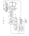
- an ultrasonic Doppler blood flow sensing apparatus comprising: transducing means for sending an ultrasonic wave into an object and receiving echoes from the same; ultrasonic diagnosing means for processing the echoes received to provide a tomogram signal; ultrasonic Doppler blood flow meter means for processing the echoes received to provide blood flow data; means for sensing electrocardiographic data of the object; gating means for producing a sampling signal in response to an electrocardiographic signal from the electrocardiographic circuit means; means for sampling and storing blood flow data sensed by the blood flow meter means in response to the sampling signal from the gating means; means for calipering a radius r of a blood vessel on the basis of tomogram-derived data from the diagnosing means; angle sensing means for sensing a cosine of 0 (cos 0) where 0 is an angle of direction of an ultrasonic beam with respect to a direction of a blood flow at a part of the object to be measured on the basis of the to
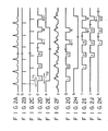
- an electrocardiograph (ECG) circuit 11 provides a cardiographic signal (Fig. 2A) in an object.
- the ECG circuit 11 is connected at the output to a monitor 22 as a display unit for visualizing the cardiographic signal.
- An ECG gate 12 is connected to the output of the ECG circuit 11 and at the first and second control terminals (Fig. 4) to the outputs of first and second preset circuits 20 and 21.
- the gate 12 responds to the signal (Fig. 2A) from the ECG circuit 11 and preset signals from the first and second preset circuits 20 and 21 to generate signals as shown in Figs. 2B to 2E and to produce a signal shown in Fig. 2G.
- a probe 17 of the known sector electronic scanning type transmits an ultrasonic beam into the object (a living body) and receives echoes returned from the inside of the living body to convert into a corresponding electrical signal.
- the probe 17 is connected to the input of an ultrasonic diagnosis device 13 and the input of a Doppler blood flow meter 14.
- the flow meter 14 may be the one disclosed in bulletin in Medical electronics Society Vol. 17, No. 3, page 214, 1979, for example.
- the blood flow meter 14 is connected at the output to a random access memory (RAM) 15 for sampling and storing a blood flow signal from the blood flow meter 14.
- the RAM 15 is further connected to another RAM 16 for reading out the blood flow data from the former RAM 15.
- the RAMs 15 and 16 are connected at the control terminals to the output of the ECG gate 12.
- the output signal (Fig. 2G) from the ECG gate 12 is applied as a sampling signal for read and write operations to the RAMs 15 and 16.
- the output of the RAM 16 is connected to the first input terminal of an arithmetic logic unit (ALU) 18 for receiving the blood flow data from the RAM 16.
- ALU arithmetic logic unit
- the ultrasonic diagnosis device 13 processes the echoes from the living body to provide data of a B scan tomogram.
- the output of the ultrasonic diagnosis device 13 is connected to a monitor 12, a cosine detector 23 and a caliper circuit or an r detector 24.
- the cosine detector 23 calculates an angle 0 of a direction of the ultrasonic beam with respect to a direction of the blood flow at a specific or effected part of the living body and its cosine, cos 0 , on the basis of the tomogram data from the diagnosis device 13.
- the caliper circuit 24 detects a radius r of a blood vessel in the specific part of the living body, using the tomogram data from the diagnosis device 13.
- the cosine detector 23 and the caliper circuit 24 are connected to the second and third input terminals of ALU 18.
- the ALU 18 calculates an average latest blood flow, or an average per-minute or per-cardiac cycle blood flow, using the blood flow data from the readout RAM 16, the angle data of cos 0 from the cosine detector 23, and the r data from the caliper circuit 24.
- the output of the ALU 18 is connected directly and through a digital-to-analog (D/A) converter to the monitor 22.
- the monitor 22 visualizes the blood flow and its related data on the specific part of the living body on the basis of the output signals from the ALU 18, the D/A converter 19, the ECG gate 12 and the diagnosis device 13.
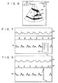
- reference numeral 31 is a blood vessel, and 32 is a direction of the ultrasonic beam transmitted.
- a maker 34 with an arrow head is displayed on the monitor screen.
- the marker 34 is rotated about a point 33 centered at the specific part until it coincides with the direction of the ultrasonic beam 32. Then, the detector 23 obtains the angle 0 of the blood flow with respect to the beam direction from the rotating angle data, and logically determines a consine of 0.
- the probe 17 is excited to send an ultrasonic beam into the living body, and receives the echoes from the living body to convert it into a corresponding electrical signal.
- the electrical echo signal is applied to the diagnosis device 13 and to the Doppler flow meter 14.
- the diagnosis device 13 processes the echo signals from the living body to provide data of a B scan tomogram.
- the tomogram data is then applied to the monitor 22 where it is visualized on a screen, and is also applied to the cosine detector 23 and the r detector 24.
- the cosine detector 23 obtains an angle 0 of the blood flow direction at the specific part or location against the direction of the ultrasonic beam emitted from the probe 17, using the tomogram data received and then calculates a cosine of 0 (cos 0).
- the cos 0 data is applied to the ALU 18.
- the r detector 24 calutates a radius r of a blood vessel at the specific location using the tomogram data.
- the r output signal is also applied to the
- the Doppler flow meter 14 picks up only the echo signals returned from the specific location from among all the incoming echo signals in order to obtain a Doppler frequency shift and thus a blood flow.
- the ECG circuit 11 detects an electrocardiographic signal as shown in Fig. 2A.
- the cardiographic signal is applied to the first input terminal of the ECG gate 12 and to the monitor 22 where it is visualized.
- the ECG gate 12 is further applied with a preset signal for setting a given delay time Tl derived from the first preset circuit 20 and another preset time tor setting a given sampling period T2 derived from the second switch circuit 21.
- the ECG gate 12 generates, using these input signals, a trigger signal (Fig. 2B) in sychronism with the peak of an R wave of the cardiographic signal, a signal (Fig. 2C) as the trigger signal delayed a delay time Tl, a sampling pulse signal (Fig.
- a pulse width T2 necessary for obtaining an average current of a blood spectrum (Fig. 2F)
- a pulse signal (Fig. 2E) for setting a period sampled by the sampling pulse signal to a period of N cardiac cycles
- a read/write signal or a sampling signal (Fig. 2G) used as a write signal for the RAM 15 and a read signal for the RAM 16.
- the sampling signal of Fig. 2G is applied at the control terminal of the RAM 15.
- the RAM 15 samples and stores the blood flow data from the blood flow meter 14 according to the sampling signal from the ECG gate 12.
- the blood flow data is written into the RAM 15 in the form of the data of 8 bits per 2.67 msec., for example.
- the blood flow data stored in the RAM 15 is read out into the RAM 16 according to the sampling signal (Fig. 2G) applied also to the RAM 16.
- the blood flow data read out from the RAM 16 is applied to the ALU 18.
- the blood flow data from the RAM 16, the cos 0 data from the cosine detector 23, and the r data from the r detector 24 are applied to the ALU 18.
- the ALU 18 calculates an average per-minute blood flow Ql and/or and average per-cardiac cycle blood flow Q2. This calculation procedure follows. Instantaneous average blood flow velocity signals Vi produced every cardiac cycle, for example, 2.67 msec., are added to one another over a period of N cardiac cycles and then the resultant sum is divided by the number of additions N. As a result, an average blood flow velcity VI per second (cm/s) is obtained.
- the per-minute average blood flow Ql is given by
- the per-minute average blood flow Ql does not designate the blood flow during the whole period of the most recent one minute, but designates the blood flow during the sampling period T2.
- the average per-beat blood flow Q2 is given by
- the average per-cardiac cycle blood flow Q2 does not designate the blood flow during the whole period of the most recent one cardiac cycle, but designates the blood flow during the sample period T2.
- N designates the number of cardiac cycles during the sampling period.
- the ALU 18 performs the above operations to obain the per-minute average blood flow Ql and/or the average per-cardiac cycle blood flow Q2.
- the result of the operation is directly applied to the monitor 22 where it is displayed in a digital fashion.
- the operation result is also applied through the D/A converter 19 to the monitor 22 where it is displayed in an analog fashion.
- the above-mentioned method measures the time of N beats.
- the result of the average blood flow may be obtained in a shorter cycle, in a manner that the average blood flow data on the N beats is stored, the stored data is shifted every time the average per-cardiac cycle blood flow data is obtained, and the shifted average blood flow data is used for calculation of the average blood flow over a period from the present beat to the past N-l cardiac cycle.
- Fig. 4 there is shown a detailed circuit arrangement of the ECG gate 12 and the preset circuits 20 and 21.
- the switch circuit 20 is made up of a fixed resistor 41 and a variable resistor 42 connected in series between ground and a power source Vcc, and an analog-to-digital (A/D) converter 43 connected to a node between the resistors 41 and 42.
- the A/D converter 43 converts an analog signal at the node and the resultant digital signal is used for setting a delay time Tl and is applied to a preset terminal Pre of a first counter 48 in the ECG gate 12.
- the preset circuit 21 is likewise made up of a fixed resistor 44 and a variable resistor 45 connected in series between ground and the power source Vcc, and an A/D converter 46 connected to a node between these resistors 44 and 45.
- the digital signal produced by the A/D converter 46 is applied as a signal for setting the sampling period T2 to a preset terminal Pre of a second counter 49 in the ECG gate 12.
- An oscillator 47 containing a crystal resonator generates a clock pulse signal at a stable frequency, and is connected at the output to clock pulse terminals Ck of the first and second counters 48 and 49.
- a trigger circuit 50 coupled at the input with the ECG circuit 11 is coupled at the output to a clear terminal CL of the first counter 48 and a first input terminal of a first flip-flop FF 51 of which the second input is connected to the output Co of the first counter 48.
- the output of the first FF 51 is connected to a clear terminal CL of the second counter 49 and to a first input terminal of a second FF 52 of which the second input terminal is coupled with the output terminal Co of the second counter 49.
- the output of the second FF 52 is connected to the input terminal Ci of a third counter 53, a first input terminal of a third FF 53 and a first input terminal of an AND gate 56.
- the Pre terminal of the third counter 53 is connected to a read only memory (ROM) 54 for storing data to direct a number of counts to be counted by the third counter.
- the output of a clear generator (not shown) externally operated by an operator is connected to the clear (CL) terminal of the third counter 53.
- the output terminal Co of the third counter 53 is connected to a second input of the third FF 54.
- the output terminal of the third FF 55 is connected to a second input terminal of the AND gate 56.
- the output of the AND gate 56 is connected to the input terminal of a shift register 57.
- the output terminal of the shift register 57 serves as the output terminal of the ECG gate 12.
- the delay time Tl is controlled by a potential at the node between the resistors 41 and 42 in the preset circuit 20. Accordingly, the delay time Tl may be set to a proper value by adjusting the variable resistor 42. A potential at the node properly set by means of the variable resistor 42 is rendered in digital form by the A/D converter 43 and is applied to the Pre terminal of the first counter 48 for preseting the delay time Tl.
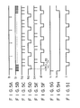
- the OSC 47 generates a clock pulse signal at a stable frequency as shown in Fig. 5B.
- the clock pulse signal is applied to the clock pulse terminal Ck of the first counter 48.
- the first counter 48 counts the clock pulse signal from the OSC 47 for the period Tl preset by the preset signal.
- the trigger circuit 50 produces a trigger pulse signal (Fig. 5A) in synchronism with the peaks of an R wave of the cardiographic signal (Fig. 2A) detected by the ECG circuit 12.
- the trigger pulse signal is applied as a clear signal to the clear terminal CL of the first counter 48.
- the first counter 48 Upon receipt of the clear pulse signal, the first counter 48 is cleared and then counts incoming clock pulses during the preset delay time, or the period Tl. When the first counter completes the count for the period Tl, it produces trigger pulses as shown in Fig. 5C.
- the counter 48 repeats this operation.
- the output signal from the counter 48 is coupled with a first input terminal of the FF 51. At this time, the FF 51 receives at the second input terminal the trigger pulses as shown in Fig. 5A.
- the first FF 51 produces pulse signals as shown in Fig. 5D, which in turn are applied to the clear terminal CL of the second counter 49.
- the clock pulse signal is applied from the OSC 47 to the clock pulse terminal of the first counter 49.
- a preset signal for presetting a preset time T2 is applied from the second preset circuit T2 to the Pre terminal of the second counter 49.
- the second preset circuit operates like the first preset circuit and hence no explanation of its operation will be given.
- the second counter 49 Responsive to the clock pulse signal, the clear signal, and the preset signal, the second counter 49 produces an output signal as shown in Fig. 5E.
- the output signal from the second counter 49 is applied to the second input terminal of the second FF 52 and the output signal from the first FF 51 is applied to the input terminal of the second counter 49.
- an output signal as shown in Fig. 5F is produced from the second FF 52.
- the output signal from the second FF 52 is applied to the input terminal Ci of the third counter 53, the input terminal of the third FF 55, and the input terminal of the AND gate 56.
- a signal for providing a preset time is applied from the ROM 54 to the preset terminal of the third counter 53.
- a clear signal is applied from the clear pulse generator to the clear terminal of the third counter 53.
- the counter 53 receives the output signal from the second FF 52, the preset signal from the ROM 54, and the clear signal from the clear signal generator to produce a pulse signal.
- the output signal from the third counter 53 is applied to the second input terminal of the third FF 55 and the output signal from the second FF 52 is applied to the input terminal of the thrid FF 55.
- the third FF 54 produces pulses as shown in Fig. 2E.
- the output signal from the third FF 55 is applied to the second input of the AND gate 56 and the output signal from the second FF 52 is applied to the first input terminal of the AND gate 56.
- the AND gate 55 produces pulses as shown in Fig. 2G.
- An output signal from the AND gate 56 is applied to the shift register 57 which then is shifted by one. Accordingly, the shift register 56 produces signals as shown in Figs. 2I, 2J and 2K.
- Fig. 6 shows some examples of displays on the monitor screen.
- a B mode tomogram is displayed on the center part in the screen.
- Three squared blocks 63 on the upper left corner indicates an average per-minute blood flow given in the digital fashion.
- numerals indicating the average per-minute blood flow are displayed at the locations of these three blocks.
- a cardiographic signal wave is traced on the upper right corner in the screen.
- the average per-minute blood flow may be easily changed to the average per-cardiac cycle blood flow, if a proper selector is used for this purpose. Further, the digital blood flow may be frozen if a proper freezing means is provided.
- the period for averaging the blood flow may be marked to the cardiographic signal wave on the upper right corner, with markers 62 at a different intensity from those of the waveform.
- Fig. 7 there are displayed an M mode tomogram 67 on the upper part of the screen, a cardiographic signal wave 68 at the middle part, and power spectrums 69 of the blood flow traced on coordinates having the abscissa representing time and the ordinate representing a blood flow velocity at the lower part of the screen.
- a combination of a plood flow scale marker 70 and a blood flow histogram 71 nay be displayed on the same location on the screen as that of the power spectrum 69, in place of the power spectrums, with provision of a proper selector for selecting either of them.
- an average per-minute blood flow 72 may be substituted for the scale-histogram combination shown in Fig. 7.
- the blood flow sensing apparatus may display an average per-minute or per-cardiac cycle blood flow on the monitor screen, with the combination of the ultrasonic diagnosis device and the Doppler blood flow meter.
Applications Claiming Priority (2)
| Application Number | Priority Date | Filing Date | Title |
|---|---|---|---|
| JP146311/81 | 1981-09-18 | ||
| JP56146311A JPS5849137A (ja) | 1981-09-18 | 1981-09-18 | 超音波血流測定装置 |
Publications (3)
| Publication Number | Publication Date |
|---|---|
| EP0075284A2 true EP0075284A2 (fr) | 1983-03-30 |
| EP0075284A3 EP0075284A3 (en) | 1986-01-29 |
| EP0075284B1 EP0075284B1 (fr) | 1989-02-08 |
Family
ID=15404804
Family Applications (1)
| Application Number | Title | Priority Date | Filing Date |
|---|---|---|---|
| EP82108566A Expired EP0075284B1 (fr) | 1981-09-18 | 1982-09-16 | Capteur ultrasonique du débit de sang |
Country Status (4)
| Country | Link |
|---|---|
| US (1) | US4501279A (fr) |
| EP (1) | EP0075284B1 (fr) |
| JP (1) | JPS5849137A (fr) |
| DE (1) | DE3279434D1 (fr) |
Cited By (8)
| Publication number | Priority date | Publication date | Assignee | Title |
|---|---|---|---|---|
| DE3512053A1 (de) * | 1984-04-02 | 1985-10-31 | Teltec Electronic Equipment AB, Lund | Geraet zur messung pulsierender teilstrukturen in einem lebenden koerper |
| EP0186732A2 (fr) * | 1984-09-21 | 1986-07-09 | Rudolf Mauser | Appareil ultrasonique pour la détermination du comportement du flux sanguin périphérique |
| AU591312B2 (en) * | 1986-07-18 | 1989-11-30 | Howmedica Inc. | Doppler tip guide wire |
| EP0386620A1 (fr) * | 1989-03-08 | 1990-09-12 | Asulab S.A. | Procédé et dispositif pour établir la relation pression-diamètre d'une artère par des mesures non invasives |
| FR2644054A1 (fr) * | 1989-03-13 | 1990-09-14 | Asulab Sa | Procede et dispositif pour etablir la relation pression-diametre d'une artere par des mesures non invasives |
| EP0458384A1 (fr) * | 1990-05-22 | 1991-11-27 | Laboratoires D'electronique Philips S.A.S. | Dispositif de mesure et de visualisation par échographie ultrasonore de débit d'un écoulement sanguin et de dilatation du vaisseau associé |
| EP0603967A1 (fr) * | 1992-12-22 | 1994-06-29 | Laboratoires D'electronique Philips S.A.S. | Dispositif et procédé de mesure d'élasticité d'une artère par échographie ultrasonore |
| CN110200613A (zh) * | 2019-04-08 | 2019-09-06 | 深圳市贝斯曼精密仪器有限公司 | 一种血流血压检测装置 |
Families Citing this family (44)
| Publication number | Priority date | Publication date | Assignee | Title |
|---|---|---|---|---|
| JPS59218141A (ja) * | 1983-05-25 | 1984-12-08 | アロカ株式会社 | 超音波診断装置 |
| JPS59218142A (ja) * | 1983-05-25 | 1984-12-08 | アロカ株式会社 | 超音波診断装置 |
| US4680708A (en) * | 1984-03-20 | 1987-07-14 | Washington University | Method and apparatus for analyzing electrocardiographic signals |
| JPS61149129A (ja) * | 1984-12-24 | 1986-07-07 | 株式会社東芝 | 超音波診断装置 |
| JPS61181449A (ja) * | 1985-02-08 | 1986-08-14 | 富士通株式会社 | 血流速度測定装置 |
| JPH0653117B2 (ja) * | 1985-07-24 | 1994-07-20 | 株式会社東芝 | 超音波血流量自動測定装置 |
| JP2557410B2 (ja) * | 1987-09-22 | 1996-11-27 | 株式会社東芝 | 超音波ドプラ血流イメージング装置 |
| US5105815A (en) * | 1987-10-08 | 1992-04-21 | Abbey Biosystems Limited | Non-invasive monitoring of cardiac output |
| US4961428A (en) * | 1988-05-02 | 1990-10-09 | Northeastern University | Non-invasive method and apparatus for describing the electrical activity of the surface of an interior organ |
| US5062427A (en) * | 1988-05-06 | 1991-11-05 | Kabushiki Kaisha Toshiba | Ultrasonic doppler apparatus |
| CH678691A5 (fr) * | 1989-03-08 | 1991-10-31 | Asulab Sa | |
| JP3381968B2 (ja) * | 1993-07-09 | 2003-03-04 | 株式会社東芝 | 超音波診断装置 |
| DE4424506C2 (de) * | 1993-07-29 | 2001-02-22 | Siemens Ag | Verfahren zur Bestimmung von Blutflußparameterwerten |
| US5701898A (en) * | 1994-09-02 | 1997-12-30 | The United States Of America As Represented By The Department Of Health And Human Services | Method and system for Doppler ultrasound measurement of blood flow |
| US5720291A (en) * | 1996-03-22 | 1998-02-24 | Advanced Technology Laboratories, Inc. | Three dimensional medical ultrasonic diagnostic image of tissue texture and vasculature |
| US20030045797A1 (en) * | 2001-08-28 | 2003-03-06 | Donald Christopher | Automatic optimization of doppler display parameters |
| US7927275B2 (en) * | 2002-08-26 | 2011-04-19 | The Cleveland Clinic Foundation | System and method of aquiring blood-vessel data |
| TR201902962T4 (tr) | 2002-08-26 | 2019-03-21 | Cleveland Clinic Found | Vasküler dokunun karakterize edilmesine yönelik sistem ve yöntem. |
| US9028415B2 (en) * | 2005-11-16 | 2015-05-12 | Cook Medical Technologies Llc | Blood flow monitor with visual display |
| WO2007092054A2 (fr) * | 2006-02-06 | 2007-08-16 | Specht Donald F | procEDE et appareil permettant de visualiser les artEres coronaires A l'aide d'ultrasons |
| US20080051661A1 (en) * | 2006-08-28 | 2008-02-28 | Kabushiki Kaisha Toshiba | Ultrasonic diagnostic apparatus and ultrasonic diagnostic method |
| EP2088932B1 (fr) | 2006-10-25 | 2020-04-08 | Maui Imaging, Inc. | Procédé et appareil de production d'images ultrasonores au moyen d'une pluralité d'orifices |
| WO2008154632A2 (fr) * | 2007-06-12 | 2008-12-18 | University Of Virginia Patent Foundation | Système et procédé pour écho-ecg combiné pour diagnostic cardiaque |
| US9247926B2 (en) | 2010-04-14 | 2016-02-02 | Maui Imaging, Inc. | Concave ultrasound transducers and 3D arrays |
| US9282945B2 (en) | 2009-04-14 | 2016-03-15 | Maui Imaging, Inc. | Calibration of ultrasound probes |
| US8602993B2 (en) * | 2008-08-08 | 2013-12-10 | Maui Imaging, Inc. | Imaging with multiple aperture medical ultrasound and synchronization of add-on systems |
| JP5485373B2 (ja) | 2009-04-14 | 2014-05-07 | マウイ イマギング,インコーポレーテッド | 複数開口の超音波アレイ位置合せ装置 |
| KR20110137829A (ko) * | 2009-04-14 | 2011-12-23 | 마우이 이미징, 인코포레이티드 | 범용 복수 개구 의료용 초음파 프로브 |
| KR102322776B1 (ko) * | 2010-02-18 | 2021-11-04 | 마우이 이미징, 인코포레이티드 | 초음파 이미지를 구성하는 방법 및 이를 위한 다중-개구 초음파 이미징 시스템 |
| WO2012051305A2 (fr) | 2010-10-13 | 2012-04-19 | Mau Imaging, Inc. | Appareil interne de sonde à ouvertures multiples et systèmes de câbles |
| EP2785253B1 (fr) | 2011-12-01 | 2023-11-15 | Maui Imaging, Inc. | Détection de mouvement par utilisation d'un doppler à ouverture basé sur l'impulsion acoustique émise et à ouvertures multiples |
| KR101348771B1 (ko) * | 2011-12-28 | 2014-01-07 | 삼성메디슨 주식회사 | 벡터 도플러를 이용하여 파티클의 움직임을 추정하는 초음파 시스템 및 방법 |
| WO2013101988A1 (fr) | 2011-12-29 | 2013-07-04 | Maui Imaging, Inc. | Imagerie par ultrasons en mode m des trajets arbitraires |
| CN104135937B (zh) | 2012-02-21 | 2017-03-29 | 毛伊图像公司 | 使用多孔超声确定材料刚度 |
| JP6399999B2 (ja) | 2012-03-26 | 2018-10-03 | マウイ イマギング,インコーポレーテッド | 重み付け係数を適用することによって超音波画像の質を改善するためのシステム及び方法 |
| CN104620128B (zh) | 2012-08-10 | 2017-06-23 | 毛伊图像公司 | 多孔径超声探头的校准 |
| JP6306012B2 (ja) | 2012-08-21 | 2018-04-04 | マウイ イマギング,インコーポレーテッド | 超音波イメージングシステムのメモリアーキテクチャ |
| JP2014050536A (ja) * | 2012-09-06 | 2014-03-20 | Hitachi Aloka Medical Ltd | 超音波診断装置 |
| US9510806B2 (en) | 2013-03-13 | 2016-12-06 | Maui Imaging, Inc. | Alignment of ultrasound transducer arrays and multiple aperture probe assembly |
| US9883848B2 (en) | 2013-09-13 | 2018-02-06 | Maui Imaging, Inc. | Ultrasound imaging using apparent point-source transmit transducer |
| JP6722656B2 (ja) | 2014-08-18 | 2020-07-15 | マウイ イマギング,インコーポレーテッド | ネットワークベース超音波イメージングシステム |
| EP3379999B1 (fr) * | 2015-11-24 | 2023-09-20 | The Regents of the University of California | Cartographie et quantification de stase sanguine et de risque de thrombose dans le coeur |
| EP3408037A4 (fr) | 2016-01-27 | 2019-10-23 | Maui Imaging, Inc. | Imagerie par ultrasons avec sondes de réseaux épars |
| JP7267754B2 (ja) * | 2019-01-22 | 2023-05-02 | 日本光電工業株式会社 | 生体情報モニタおよび生体情報測定システム |
Citations (1)
| Publication number | Priority date | Publication date | Assignee | Title |
|---|---|---|---|---|
| EP0035213A1 (fr) * | 1980-02-27 | 1981-09-09 | Kabushiki Kaisha Toshiba | Appareil de diagnostic à ultrasons |
Family Cites Families (4)
| Publication number | Priority date | Publication date | Assignee | Title |
|---|---|---|---|---|
| US4271842A (en) * | 1978-03-03 | 1981-06-09 | Smith Kline Instruments, Inc. | Apparatus and method for providing multiple ultrasonic sector image displays |
| US4217909A (en) * | 1978-08-23 | 1980-08-19 | General Electric Company | Directional detection of blood velocities in an ultrasound system |
| JPS55143132A (en) * | 1979-04-26 | 1980-11-08 | Kuniyasu Furuhira | Measuring device for medical treatment |
| JPS56112226A (en) * | 1980-02-12 | 1981-09-04 | Tokyo Shibaura Electric Co | Ultrasonic blood stream measuring apparatus |
-
1981
- 1981-09-18 JP JP56146311A patent/JPS5849137A/ja active Pending
-
1982
- 1982-09-14 US US06/418,001 patent/US4501279A/en not_active Expired - Fee Related
- 1982-09-16 DE DE8282108566T patent/DE3279434D1/de not_active Expired
- 1982-09-16 EP EP82108566A patent/EP0075284B1/fr not_active Expired
Patent Citations (1)
| Publication number | Priority date | Publication date | Assignee | Title |
|---|---|---|---|---|
| EP0035213A1 (fr) * | 1980-02-27 | 1981-09-09 | Kabushiki Kaisha Toshiba | Appareil de diagnostic à ultrasons |
Cited By (11)
| Publication number | Priority date | Publication date | Assignee | Title |
|---|---|---|---|---|
| DE3512053A1 (de) * | 1984-04-02 | 1985-10-31 | Teltec Electronic Equipment AB, Lund | Geraet zur messung pulsierender teilstrukturen in einem lebenden koerper |
| EP0186732A2 (fr) * | 1984-09-21 | 1986-07-09 | Rudolf Mauser | Appareil ultrasonique pour la détermination du comportement du flux sanguin périphérique |
| EP0186732A3 (en) * | 1984-09-21 | 1988-09-21 | Rudolf Mauser | Ultrasonic determination of peripheral blood flow behaviour |
| AU591312B2 (en) * | 1986-07-18 | 1989-11-30 | Howmedica Inc. | Doppler tip guide wire |
| EP0386620A1 (fr) * | 1989-03-08 | 1990-09-12 | Asulab S.A. | Procédé et dispositif pour établir la relation pression-diamètre d'une artère par des mesures non invasives |
| FR2644054A1 (fr) * | 1989-03-13 | 1990-09-14 | Asulab Sa | Procede et dispositif pour etablir la relation pression-diametre d'une artere par des mesures non invasives |
| EP0458384A1 (fr) * | 1990-05-22 | 1991-11-27 | Laboratoires D'electronique Philips S.A.S. | Dispositif de mesure et de visualisation par échographie ultrasonore de débit d'un écoulement sanguin et de dilatation du vaisseau associé |
| FR2662348A1 (fr) * | 1990-05-22 | 1991-11-29 | Philips Electronique Lab | Dispositif de mesure et de visualisation par echographie ultrasonore de debit d'un ecoulement sanguin et de dilatation du vaisseau associe. |
| EP0603967A1 (fr) * | 1992-12-22 | 1994-06-29 | Laboratoires D'electronique Philips S.A.S. | Dispositif et procédé de mesure d'élasticité d'une artère par échographie ultrasonore |
| CN110200613A (zh) * | 2019-04-08 | 2019-09-06 | 深圳市贝斯曼精密仪器有限公司 | 一种血流血压检测装置 |
| CN110200613B (zh) * | 2019-04-08 | 2024-02-20 | 深圳市贝斯曼精密仪器有限公司 | 一种血流血压检测装置 |
Also Published As
| Publication number | Publication date |
|---|---|
| JPS5849137A (ja) | 1983-03-23 |
| EP0075284B1 (fr) | 1989-02-08 |
| US4501279A (en) | 1985-02-26 |
| DE3279434D1 (en) | 1989-03-16 |
| EP0075284A3 (en) | 1986-01-29 |
Similar Documents
| Publication | Publication Date | Title |
|---|---|---|
| US4501279A (en) | Ultrasonic blood flow sensing apparatus | |
| US4373533A (en) | Ultrasonic diagnosing apparatus | |
| US5634465A (en) | Continuous display of cardiac blood flow information | |
| Bohs et al. | A real time system for quantifying and displaying two-dimensional velocities using ultrasound | |
| US3561430A (en) | Fetal heartbeat rate instrument for monitoring fetal distress | |
| EP0033977B1 (fr) | Appareil pour la mesure de l'écoulement sanguin à ultrasons | |
| US4318413A (en) | Ultrasonic diagnostic apparatus | |
| EP0573249A1 (fr) | Affichage en continu des vitesses maximales et moyennes d'écoulement du sang | |
| JPH08173422A (ja) | 超音波診断装置 | |
| US4735211A (en) | Ultrasonic measurement apparatus | |
| JPS6247537B2 (fr) | ||
| US5103826A (en) | Device for measurement and display of physiological parameters of a blood flow by ultrasonic echography | |
| US4771789A (en) | Ultrasonic device for measuring acceleration of moving reflective member | |
| US5813986A (en) | Method of identifying the time phase of the state of an organ to be observed, and ultrasonic diagnostic apparatus based on the same | |
| US4850361A (en) | Ultrasonic imaging apparatus | |
| WO1986002819A1 (fr) | Appareil et procede de surveillance des organes du corps humain | |
| US3818898A (en) | Echo-encephalographic apparatus | |
| KR840002100B1 (ko) | 초음파 진단장치 | |
| JP2768959B2 (ja) | 超音波診断装置 | |
| KR840002116B1 (ko) | 초음파 혈류측정장치 | |
| JPH0315462B2 (fr) | ||
| JPH04138146A (ja) | 相関型超音波流速測定装置 | |
| JPS6096233A (ja) | 超音波血流測定装置 | |
| JPH0512934B2 (fr) | ||
| JPS62156508A (ja) | 皮下脂肪厚測定装置 |
Legal Events
| Date | Code | Title | Description |
|---|---|---|---|
| PUAI | Public reference made under article 153(3) epc to a published international application that has entered the european phase |
Free format text: ORIGINAL CODE: 0009012 |
|
| 17P | Request for examination filed |
Effective date: 19821013 |
|
| AK | Designated contracting states |
Designated state(s): DE FR GB NL |
|
| RAP1 | Party data changed (applicant data changed or rights of an application transferred) |
Owner name: KABUSHIKI KAISHA TOSHIBA |
|
| PUAL | Search report despatched |
Free format text: ORIGINAL CODE: 0009013 |
|
| RHK1 | Main classification (correction) |
Ipc: A61B 8/06 |
|
| AK | Designated contracting states |
Designated state(s): DE FR GB NL |
|
| 17Q | First examination report despatched |
Effective date: 19870821 |
|
| GRAA | (expected) grant |
Free format text: ORIGINAL CODE: 0009210 |
|
| AK | Designated contracting states |
Kind code of ref document: B1 Designated state(s): DE FR GB NL |
|
| REF | Corresponds to: |
Ref document number: 3279434 Country of ref document: DE Date of ref document: 19890316 |
|
| ET | Fr: translation filed | ||
| PLBE | No opposition filed within time limit |
Free format text: ORIGINAL CODE: 0009261 |
|
| STAA | Information on the status of an ep patent application or granted ep patent |
Free format text: STATUS: NO OPPOSITION FILED WITHIN TIME LIMIT |
|
| 26N | No opposition filed | ||
| PGFP | Annual fee paid to national office [announced via postgrant information from national office to epo] |
Ref country code: GB Payment date: 19970908 Year of fee payment: 16 |
|
| PGFP | Annual fee paid to national office [announced via postgrant information from national office to epo] |
Ref country code: FR Payment date: 19970909 Year of fee payment: 16 |
|
| PG25 | Lapsed in a contracting state [announced via postgrant information from national office to epo] |
Ref country code: GB Free format text: LAPSE BECAUSE OF NON-PAYMENT OF DUE FEES Effective date: 19980916 |
|
| PGFP | Annual fee paid to national office [announced via postgrant information from national office to epo] |
Ref country code: DE Payment date: 19980925 Year of fee payment: 17 |
|
| PGFP | Annual fee paid to national office [announced via postgrant information from national office to epo] |
Ref country code: NL Payment date: 19980929 Year of fee payment: 17 |
|
| GBPC | Gb: european patent ceased through non-payment of renewal fee |
Effective date: 19980916 |
|
| PG25 | Lapsed in a contracting state [announced via postgrant information from national office to epo] |
Ref country code: FR Free format text: LAPSE BECAUSE OF NON-PAYMENT OF DUE FEES Effective date: 19990531 |
|
| REG | Reference to a national code |
Ref country code: FR Ref legal event code: ST |
|
| PG25 | Lapsed in a contracting state [announced via postgrant information from national office to epo] |
Ref country code: NL Free format text: LAPSE BECAUSE OF NON-PAYMENT OF DUE FEES Effective date: 20000401 |
|
| NLV4 | Nl: lapsed or anulled due to non-payment of the annual fee |
Effective date: 20000401 |
|
| PG25 | Lapsed in a contracting state [announced via postgrant information from national office to epo] |
Ref country code: DE Free format text: LAPSE BECAUSE OF NON-PAYMENT OF DUE FEES Effective date: 20000701 |