EP0074823A2 - Liquid fuel combustion apparatus - Google Patents
Liquid fuel combustion apparatus Download PDFInfo
- Publication number
- EP0074823A2 EP0074823A2 EP82304785A EP82304785A EP0074823A2 EP 0074823 A2 EP0074823 A2 EP 0074823A2 EP 82304785 A EP82304785 A EP 82304785A EP 82304785 A EP82304785 A EP 82304785A EP 0074823 A2 EP0074823 A2 EP 0074823A2
- Authority
- EP
- European Patent Office
- Prior art keywords
- oxygen
- air
- burner
- enriched air
- channel
- Prior art date
- Legal status (The legal status is an assumption and is not a legal conclusion. Google has not performed a legal analysis and makes no representation as to the accuracy of the status listed.)
- Granted
Links
Images

Classifications
-
- F—MECHANICAL ENGINEERING; LIGHTING; HEATING; WEAPONS; BLASTING
- F23—COMBUSTION APPARATUS; COMBUSTION PROCESSES
- F23D—BURNERS
- F23D11/00—Burners using a direct spraying action of liquid droplets or vaporised liquid into the combustion space
- F23D11/10—Burners using a direct spraying action of liquid droplets or vaporised liquid into the combustion space the spraying being induced by a gaseous medium, e.g. water vapour
-
- F—MECHANICAL ENGINEERING; LIGHTING; HEATING; WEAPONS; BLASTING
- F23—COMBUSTION APPARATUS; COMBUSTION PROCESSES
- F23C—METHODS OR APPARATUS FOR COMBUSTION USING FLUID FUEL OR SOLID FUEL SUSPENDED IN A CARRIER GAS OR AIR
- F23C7/00—Combustion apparatus characterised by arrangements for air supply
-
- F—MECHANICAL ENGINEERING; LIGHTING; HEATING; WEAPONS; BLASTING
- F23—COMBUSTION APPARATUS; COMBUSTION PROCESSES
- F23L—SUPPLYING AIR OR NON-COMBUSTIBLE LIQUIDS OR GASES TO COMBUSTION APPARATUS IN GENERAL ; VALVES OR DAMPERS SPECIALLY ADAPTED FOR CONTROLLING AIR SUPPLY OR DRAUGHT IN COMBUSTION APPARATUS; INDUCING DRAUGHT IN COMBUSTION APPARATUS; TOPS FOR CHIMNEYS OR VENTILATING SHAFTS; TERMINALS FOR FLUES
- F23L15/00—Heating of air supplied for combustion
- F23L15/04—Arrangements of recuperators
-
- F—MECHANICAL ENGINEERING; LIGHTING; HEATING; WEAPONS; BLASTING
- F23—COMBUSTION APPARATUS; COMBUSTION PROCESSES
- F23L—SUPPLYING AIR OR NON-COMBUSTIBLE LIQUIDS OR GASES TO COMBUSTION APPARATUS IN GENERAL ; VALVES OR DAMPERS SPECIALLY ADAPTED FOR CONTROLLING AIR SUPPLY OR DRAUGHT IN COMBUSTION APPARATUS; INDUCING DRAUGHT IN COMBUSTION APPARATUS; TOPS FOR CHIMNEYS OR VENTILATING SHAFTS; TERMINALS FOR FLUES
- F23L7/00—Supplying non-combustible liquids or gases, other than air, to the fire, e.g. oxygen, steam
- F23L7/007—Supplying oxygen or oxygen-enriched air
-
- F—MECHANICAL ENGINEERING; LIGHTING; HEATING; WEAPONS; BLASTING
- F23—COMBUSTION APPARATUS; COMBUSTION PROCESSES
- F23D—BURNERS
- F23D2900/00—Special features of, or arrangements for burners using fluid fuels or solid fuels suspended in a carrier gas
- F23D2900/00006—Liquid fuel burners using pure oxygen or O2-enriched air as oxidant
-
- Y—GENERAL TAGGING OF NEW TECHNOLOGICAL DEVELOPMENTS; GENERAL TAGGING OF CROSS-SECTIONAL TECHNOLOGIES SPANNING OVER SEVERAL SECTIONS OF THE IPC; TECHNICAL SUBJECTS COVERED BY FORMER USPC CROSS-REFERENCE ART COLLECTIONS [XRACs] AND DIGESTS
- Y02—TECHNOLOGIES OR APPLICATIONS FOR MITIGATION OR ADAPTATION AGAINST CLIMATE CHANGE
- Y02E—REDUCTION OF GREENHOUSE GAS [GHG] EMISSIONS, RELATED TO ENERGY GENERATION, TRANSMISSION OR DISTRIBUTION
- Y02E20/00—Combustion technologies with mitigation potential
- Y02E20/34—Indirect CO2mitigation, i.e. by acting on non CO2directly related matters of the process, e.g. pre-heating or heat recovery
Definitions
- the present invention relates to an apparatus for combustion of liquid fuels.
- the object of the present invention is to provide an apparatus for burning liquid fuels such as heavy oil with satisfactory results, bringing about a solution to such technical problem as mentioned above.
- a liquid fuel combustion appparatus having a burner for atomizing and burning the liquid fuels, which comprises supply means for supplying oxygen-enriched air obtained by passing normal air through an oxygen permselective membrane to the burner as air for combustion.
- liquid fuel is atomized by gaseous fuel and, besides, oxygen-enriched air is utilized, it is possible to achieve a satisfactory combustion of liquid fuels such as heavy oil with the generation of NOx restrained.
- liquid fuels are atomised with gaseous fuels or nitrogen-enriched air.
- oxygen-enriched air or air for supplying an oxygen permselective membrane is preheated with exhaust gas by heat exchange.
- the oxygen-enriched air is obtained from the normal air, and supplied to the burner as primary air.
- liquid fuel is atomized by means of nitrogen-enriched air, while oxygen-enriched air is supplied as the secondary air; therefore it is possible to achieve a satisfactory combustion, with a reduction in the amount of NOx generated.
- first channel, second channel and third channel concentrically disposed in the order from inside outward in the radial direction.
- the first channel is for use to be supplied with liquid fuels
- the second channel is for use to be supplied with oxygen-enriched air formed by means of oxygen-enriched air generating means
- the third channel is for use to be supplied with normal air.
- liquid fuel is atomized by an air of which the concentration of oxygen has been made higher by utilization of an oxygen enriching means; therefore an improvement is brought about in the combustion temperature of liquid fuels.
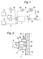
- FIG. 1 is the diagram of an example of the embodiment of the present invention.
- a combustion furnace 1 is provided with a burner 2.
- This burner 2 is supplied with a liquid fuel, for example, heavy oil, stored in a tank 3, by means of a pump 5 provided midway in a pipe conduit 4. It is also supplied with a gaseous fuel, for example town gas or liquefied natural gas, from a tank 6, through a pipe conduit 7.
- oxygen-enriched air obtained by an oxygen-enriched air generating means 8 is supplied, as the primary air, to the burner 2 by means of an induction fan 10 provided midway in a pipe conduit 9.
- air drawn in from the atmosphere by a force blower 11 is supplied through a pipe conduit 12 to the burner 2, as the secondary air.
- liquid fuel is atomized by gaseous fuel and is burned with the primary and secondary airs.
- an efficient combustion with a reduction in the amount of NOx generated, is realized.
- Waste gas from the combustion in the burner 2 is exhausted from an outlet of the combustion furnace 1 through an exhaust gas duct 13, induced into it by an induction fan 24 provided at its end.
- an induction fan 24 provided at its end.
- a heat exchanger 14 Midway in the exhaust gas duct 13, there is provided a heat exchanger 14 for the purpose of heat exchange between combustion waste gas and air.
- the oxygen-enriched air generating means 8 is provided with an oxygen permselective membrane 15 which is made of an ultrathin film of high molecular silicon compound; and this oxygen permselective membrane 15 performs the function of increasing the concentration of oxygen in the air flowing through it to about 23 to 31 %. Furthermore, said oxygen permselective membrane 15 is possessed of such a property that the higher the temperature of air flowing through it, the larger becomes the amount of oxygen-enriched air obtained. For instance, when the air temperature is raised from 20°C to 80°C, it is possible to obtain about twice as much oxygen-enriched air with the same concentration of oxygen.
- air preheated by the heat exchanger 14 is introduced through a pipe conduit 16. Accordingly, it is possible to obtain a relatively large amount of oxygen-enriched air; and this oxygen-enriched air is introduced into the burner 2 through the pipe conduit 9, by means of the induction fan 10.
- Fig. 2 is an enlarged cross-sectional view of the burner 2, showing its structure.
- the burner 2 comprises an external casing 18 in cylindrical form, with a bottom covering the opening 17, an internal casing 19 in cylindrical form, which is concentrically thrusted into the external casing 18 and which has a bottom with an opening toward the opening 17 of the main body of furnace la, and a fuel spraying cylinder 20 which is concentrically thrusted into the internal casing 19.
- the fuel spraying cylinder 20 is a two-fluid sprayer; and it can be either of the so-called "inside mixing type" or of the "outside mixing type".
- a pipe conduit 4 for supply of liquid fuel and a pipe conduit 7 for supply of gaseous fuel are connected to the fuel spraying cylinder 20.
- liquid fuel is jetted by the fuel spraying cylinder 20, as it is atomized by gaseous fuel.
- the mixture of atomized liquid fuel and gaseous fuel burns firstly with the primary air which is enriched with oxygen. For this reason, the combustion goes on in an atmosphere having a relatively high concentration of oxygen in its initial stage, hence the efficiency of combustion is improved. Accordingly, high-temperature flames are formed and, in proportion,the luminous flame radiation increases, thus bringing about an improvement in the thermal efficiency of the combustion furnace 1.
- the combustion furnace 1 with an improvement in the burning condition of fuel by virtue of the burner 2, the combustion chamber load is increased; therefore, its size, as a whole, can be made smaller.
- the combustion furnace 1 is equipped with an apparatus for desulfurization and/or denitration, the reduction in the amount of combustion gas exhausted, in virtue of oxygen-enriched air used in the burner 2, serves to alleviate the load on such an equipment.
- Fig. 3 is the diagram of another example of the embodiment of this invention.
- an air with a relatively low concentration of oxygen in other words, nitrogen-enriched air, from the oxygen-enriched air generating means 8, is supplied to the burner 2 through a pipe conduit 25, by means of an induction fan 27 provided midway in it.
- liquid fuel is atomized by the nitrogen-enriched air, as the primary air, and oxygen-enriched air is supplied to it as the secondary air. Accordingly, an efficient combustion, with a reduction in the amount of NOx generated, is realized.
- Waste gas from the combustion in the burner 2 is exhausted from an outlet of the combustion furnace 1 through the exhaust gas duct 13, induced into it by the induction fan 24 provided at its end, into the atmosphere.
- the heat exchanger 14 for the purpose of heat exchange between the oxygen-enriched air downstream the induction fan 10 in the pipe conduit 9 and combustion waste gas. Accordingly, oxygen-enriched air is supplied to the burner 2 after having been preheated.
- the concentration of oxygen in the air remaining in the upstream of the oxygen permselective membrane 15 becomes relatively low in proportion to the efficiency of oxygen enriching function of the oxygen permselective membrane 15.
- the pipe conduit 25 is connected to the oxygen-enriched air generating means 8 at the upstream side of the oxygen permselective membrane 15.
- Fig. 4 is an enlarged cross-sectional view of the burner 2 in Fig. 3, showing its structure.
- the burner 2 consists of a wind box 26 covering the opening 17 of the main body of furnace la and the fuel spraying cylinder 20 thrusted into it.
- This fuel spraying cylinder 20 is a two-fluid sprayer hitherto well known; and it can be either of the so-called "inside mixing type” or of the "outside mixing type".
- To the fuel spraying cylinder 20 are connected the fuel supply pipe 4 and the pipe conduit 7. Further, to the wind box 26 is connected the pipe conduit 9.
- liquid fuel is jetted from the fuel spraying cylinder 20 as it is atomized by nitrogen-enriched air.
- the oxygen-enriched air is preheated, the combustion efficiency is further enhanced.
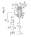
- F ig. 5 is an enlarged cross-sectional view of the burner 2 in-still another example of the embodiment of the present invention.
- the main body 31 of this burner 2 there are formed, by a spray nozzle 32 and an air nozzle 33, three channels, viz., the first channel 34, the second channel 35 and the third channel 36, concentrically disposed in the order mentioned from inside outward in the radial direction.
- burner tile 37 In front of the main body 31, there are provided burner tile 37 (at left in the figure).
- the first channel 34 the innermost in the radial direction, is supplied liquid fuel.
- the third channel 36 radially the outermost, is supplied air by means of a force fan 38.
- the second channel 35 is supplied, through a pipe conduit 42, an air of which the oxygen concentration has been made higher by the oxygen permselective membrane 15, by means of a vacuum pump 40 and a blower 41.
- the vacuum pump 40 sucks air from the oxygen permselective membrane 15 at, for instance, -600mmHg and supplies the blower 41 with oxygen-enriched air at about the atmospheric pressure.
- the oxgen permselective membrane 15 has such a property that, as soon as there begins the transmission of air through it, there immediately takes place polarization of a hard-to-permeate gas on the surface of membrane, hampering separation of oxygen from air. To prevent such, it is essential that new air be constantly supplied to the surface of membrane.
- the use of the vacuum pump 40 which induces air to permeate the oxgen permselective membrane 15 ensures the flow of necessary amount of air through the membrane, offering a great advantage in respect of savings in energy.
- the blower 41 For the purpose of prevention of occurrence of pulsation in the flow of gas from the vacuum pump 40, there is provided the blower 41; and this ensures the supply of oxygen-enriched air through the pipe conduit 42 at a certain fixed rate of flow.
- the flow rate of oxygen-enriched air can be controlled by a flow-rate control valve 48 provided midway in a bypass 47 of the pipe conduit 42 connecting the vacuum pump 40 with the oxygen-enriched air generating means 8 and the burner 2.
- Oxygen-enriched air passes through the second channel 35; and, at the end of the main body 31 of the burner 2, it atomizes liquid fuel from the first channel 34. Liquid fuel thus atomized mixes with oxygen-enriched air; hence a combustion at very high temperature can be realized.
Abstract
Description
- The present invention relates to an apparatus for combustion of liquid fuels.
- It has heretofore been difficult to effectuate a satisfactory combustion of liquid fuels having a high degree of viscosity and, in addition, containing a large amount of organic nitrogen compounds, for example, heavy oil.
- The object of the present invention is to provide an apparatus for burning liquid fuels such as heavy oil with satisfactory results, bringing about a solution to such technical problem as mentioned above.
- To accomplish the foregoing object, there is provided a liquid fuel combustion appparatus, having a burner for atomizing and burning the liquid fuels, which comprises supply means for supplying oxygen-enriched air obtained by passing normal air through an oxygen permselective membrane to the burner as air for combustion.
- According to the present invention, liquid fuel is atomized by gaseous fuel and, besides, oxygen-enriched air is utilized, it is possible to achieve a satisfactory combustion of liquid fuels such as heavy oil with the generation of NOx restrained.
- According to the preferred embodiment of the invention, liquid fuels are atomised with gaseous fuels or nitrogen-enriched air. In addition, oxygen-enriched air or air for supplying an oxygen permselective membrane is preheated with exhaust gas by heat exchange. Furthermore, the oxygen-enriched air is obtained from the normal air, and supplied to the burner as primary air.
- According to this example, it has been so devised that liquid fuel is atomized by means of nitrogen-enriched air, while oxygen-enriched air is supplied as the secondary air; therefore it is possible to achieve a satisfactory combustion, with a reduction in the amount of NOx generated.
- In accordance with the invention, there are provided first channel, second channel and third channel concentrically disposed in the order from inside outward in the radial direction. The first channel is for use to be supplied with liquid fuels, the second channel is for use to be supplied with oxygen-enriched air formed by means of oxygen-enriched air generating means, and the third channel is for use to be supplied with normal air.
- According to the embodiment, it is so devised that liquid fuel is atomized by an air of which the concentration of oxygen has been made higher by utilization of an oxygen enriching means; therefore an improvement is brought about in the combustion temperature of liquid fuels.
- A detailed description of the invention will be made with reference to the accompanying drawings wherein like numerals designate corresponding parts in the figures.
- Fig. 1 is the diagram of an example of the embodiment of the present invention;
- Fig. 2 is an enlarged cross-sectional view of the burner in Fig. 1, showing its structure;
- Fig. 3 is the diagram of another example of the embodiment of this invention;
- Fig. 4 is an enlarged cross-sectional view of the burner in Fig. 3,,showing its structure; and
- Fig. 5 is an enlarged cross-sectional view of the burner in still another embodiment of the invention.
- Fig. 1 is the diagram of an example of the embodiment of the present invention. A
combustion furnace 1 is provided with aburner 2. Thisburner 2 is supplied with a liquid fuel, for example, heavy oil, stored in atank 3, by means of apump 5 provided midway in apipe conduit 4. It is also supplied with a gaseous fuel, for example town gas or liquefied natural gas, from atank 6, through apipe conduit 7. Further, oxygen-enriched air obtained by an oxygen-enriched air generating means 8 is supplied, as the primary air, to theburner 2 by means of aninduction fan 10 provided midway in apipe conduit 9. Still further, air drawn in from the atmosphere by aforce blower 11 is supplied through apipe conduit 12 to theburner 2, as the secondary air. - In the
burner 2, liquid fuel is atomized by gaseous fuel and is burned with the primary and secondary airs. In virtue of such, an efficient combustion, with a reduction in the amount of NOx generated, is realized. Waste gas from the combustion in theburner 2 is exhausted from an outlet of thecombustion furnace 1 through anexhaust gas duct 13, induced into it by aninduction fan 24 provided at its end. Midway in theexhaust gas duct 13, there is provided aheat exchanger 14 for the purpose of heat exchange between combustion waste gas and air. - The oxygen-enriched air generating means 8 is provided with an oxygen
permselective membrane 15 which is made of an ultrathin film of high molecular silicon compound; and this oxygenpermselective membrane 15 performs the function of increasing the concentration of oxygen in the air flowing through it to about 23 to 31 %. Furthermore, said oxygenpermselective membrane 15 is possessed of such a property that the higher the temperature of air flowing through it, the larger becomes the amount of oxygen-enriched air obtained. For instance, when the air temperature is raised from 20°C to 80°C, it is possible to obtain about twice as much oxygen-enriched air with the same concentration of oxygen. Into such oxygen-enriched air generating means 8 as described above, air preheated by theheat exchanger 14 is introduced through apipe conduit 16. Accordingly, it is possible to obtain a relatively large amount of oxygen-enriched air; and this oxygen-enriched air is introduced into theburner 2 through thepipe conduit 9, by means of theinduction fan 10. - Fig. 2 is an enlarged cross-sectional view of the
burner 2, showing its structure. At a part of the main body of furnace la of thecombustion furnace 1, there is formed anopening 17; and at this opening 17, there is installed theburner 2, facing the inside of thecombustion furnace 1. Theburner 2 comprises anexternal casing 18 in cylindrical form, with a bottom covering theopening 17, aninternal casing 19 in cylindrical form, which is concentrically thrusted into theexternal casing 18 and which has a bottom with an opening toward the opening 17 of the main body of furnace la, and a fuel sprayingcylinder 20 which is concentrically thrusted into theinternal casing 19. Between the exterior surface of thefuel spraying cylinder 20 and the interior surface of theinternal casing 19, there is formed theprimary air channel 21 in annular form; and midway in thisprimary air channel 21, there is provided afixed vane 22 on the exterior surface of thefuel spraying cylinder 20. Further, between the exterior surface of theinternal casing 19 and the interior surface of theexternal casing 18, there is formed thesecondary air channel 23 in annular form. The fuel sprayingcylinder 20 is a two-fluid sprayer; and it can be either of the so-called "inside mixing type" or of the "outside mixing type". - To the
fuel spraying cylinder 20 are connected apipe conduit 4 for supply of liquid fuel and apipe conduit 7 for supply of gaseous fuel. Further, to theinternal casing 19 is connected apipe conduit 9 for supply of oxygen-enriched air to theprimary air channel 21; and to theexternal casing 18 is connected apipe conduit 12 for supply of air which is not oxygen-enriched to thesecondary air channel 23. - Into the
burner 2 as described above, liquid fuel is jetted by thefuel spraying cylinder 20, as it is atomized by gaseous fuel. The mixture of atomized liquid fuel and gaseous fuel burns firstly with the primary air which is enriched with oxygen. For this reason, the combustion goes on in an atmosphere having a relatively high concentration of oxygen in its initial stage, hence the efficiency of combustion is improved. Accordingly, high-temperature flames are formed and, in proportion,the luminous flame radiation increases, thus bringing about an improvement in the thermal efficiency of thecombustion furnace 1. - There is, on the other hand, a possibility of the formation of high-temperature flames giving rise to an increase of the amount of NOx generated. However, as the result of experiments carried out by the inventor, it was found out that, where the liquid fuel used is heavy oil, when the amount of gaseous fuel supplied is set at 10 to 40 %, in terms of calories, of the total amount of combustibles, a reduction in the amount of NOx generated can be realized. When, moreover, the amount of gaseous fuel supplied is set as above, there is brought about an improvement in the brightness of flames and the thermal efficiency is further enhanced.
- As for the
combustion furnace 1, with an improvement in the burning condition of fuel by virtue of theburner 2, the combustion chamber load is increased; therefore, its size, as a whole, can be made smaller. Where, moreover, thecombustion furnace 1 is equipped with an apparatus for desulfurization and/or denitration, the reduction in the amount of combustion gas exhausted, in virtue of oxygen-enriched air used in theburner 2, serves to alleviate the load on such an equipment. - It is to be noted that, as another example of the embodiment of this invention, there can be an omission of the
heat exchanger 14, and that oxygen-enriched air may be used both for the primary air and the secondary air. It is to be further noted that the structure of theburner 2 is not limited to that which is shown in Fig. 2. - Fig. 3 is the diagram of another example of the embodiment of this invention.
- In this example, whilst air enriched with oxygen by means of the
induction fan 10 provided midway in thepipe conduit 9, to theburner 2, an air with a relatively low concentration of oxygen, in other words, nitrogen-enriched air, from the oxygen-enriched air generating means 8, is supplied to theburner 2 through apipe conduit 25, by means of aninduction fan 27 provided midway in it. - In the
burner 2, liquid fuel is atomized by the nitrogen-enriched air, as the primary air, and oxygen-enriched air is supplied to it as the secondary air. Accordingly, an efficient combustion, with a reduction in the amount of NOx generated, is realized. Waste gas from the combustion in theburner 2 is exhausted from an outlet of thecombustion furnace 1 through theexhaust gas duct 13, induced into it by theinduction fan 24 provided at its end, into the atmosphere. In addition, midway in theexhaust gas duct 13, there is provided theheat exchanger 14 for the purpose of heat exchange between the oxygen-enriched air downstream theinduction fan 10 in thepipe conduit 9 and combustion waste gas. Accordingly, oxygen-enriched air is supplied to theburner 2 after having been preheated. - In the oxygen-enriched air generating means 8, the concentration of oxygen in the air remaining in the upstream of the oxygen
permselective membrane 15 becomes relatively low in proportion to the efficiency of oxygen enriching function of the oxygenpermselective membrane 15. For the purpose of supplying this nitrogen-enriched air to theburner 2, thepipe conduit 25 is connected to the oxygen-enriched air generating means 8 at the upstream side of the oxygenpermselective membrane 15. - Fig. 4 is an enlarged cross-sectional view of the
burner 2 in Fig. 3, showing its structure. Theburner 2 consists of awind box 26 covering the opening 17 of the main body of furnace la and thefuel spraying cylinder 20 thrusted into it. Thisfuel spraying cylinder 20 is a two-fluid sprayer hitherto well known; and it can be either of the so-called "inside mixing type" or of the "outside mixing type". To thefuel spraying cylinder 20 are connected thefuel supply pipe 4 and thepipe conduit 7. Further, to thewind box 26 is connected thepipe conduit 9. - In the
burner 2, liquid fuel is jetted from thefuel spraying cylinder 20 as it is atomized by nitrogen-enriched air. It is a common knowledge that, when steam or gaseous fuel is utilized as an atomizing medium of liquid fuel, the amount of NOx generated is reduced; and it is obvious that, even if liquid fuel is atomized by utilization of nitrogen-enriched air, as the primary air, like in this case, there is also a reduction in the amount of NOx generated. Moreover, since oxygen-enriched air is supplied as the secondary air, there occurs no degradation of the combustion efficiency of theburner 2, but a satisfactory combustion can be maintained. - As, furthermore, the oxygen-enriched air is preheated, the combustion efficiency is further enhanced.
- Fig. 5 is an enlarged cross-sectional view of the
burner 2 in-still another example of the embodiment of the present invention. In themain body 31 of thisburner 2, there are formed, by aspray nozzle 32 and anair nozzle 33, three channels, viz., thefirst channel 34, thesecond channel 35 and thethird channel 36, concentrically disposed in the order mentioned from inside outward in the radial direction. In front of themain body 31, there are provided burner tile 37 (at left in the figure). Into thefirst channel 34, the innermost in the radial direction, is supplied liquid fuel. Into thethird channel 36, radially the outermost, is supplied air by means of aforce fan 38. Into thesecond channel 35 is supplied, through apipe conduit 42, an air of which the oxygen concentration has been made higher by theoxygen permselective membrane 15, by means of avacuum pump 40 and ablower 41. - The
vacuum pump 40 sucks air from theoxygen permselective membrane 15 at, for instance, -600mmHg and supplies theblower 41 with oxygen-enriched air at about the atmospheric pressure. The oxgen permselectivemembrane 15 has such a property that, as soon as there begins the transmission of air through it, there immediately takes place polarization of a hard-to-permeate gas on the surface of membrane, hampering separation of oxygen from air. To prevent such, it is essential that new air be constantly supplied to the surface of membrane. The use of thevacuum pump 40 which induces air to permeate the oxgen permselectivemembrane 15 ensures the flow of necessary amount of air through the membrane, offering a great advantage in respect of savings in energy. For the purpose of prevention of occurrence of pulsation in the flow of gas from thevacuum pump 40, there is provided theblower 41; and this ensures the supply of oxygen-enriched air through thepipe conduit 42 at a certain fixed rate of flow. The flow rate of oxygen-enriched air can be controlled by a flow-rate control valve 48 provided midway in abypass 47 of thepipe conduit 42 connecting thevacuum pump 40 with the oxygen-enriched air generating means 8 and theburner 2. - Oxygen-enriched air passes through the
second channel 35; and, at the end of themain body 31 of theburner 2, it atomizes liquid fuel from thefirst channel 34. Liquid fuel thus atomized mixes with oxygen-enriched air; hence a combustion at very high temperature can be realized. - The invention may be embodied in other specific forms without departing from the spirit or essential characteristics thereof. The present embodiments are therefore to be considered in all respects as illustrative and not restrictive, the scope of the invention being indicated by the appended claims rather than by the foregoing description and all changes which come within the meaning and range of equivalency of the claims are therefore intended to be embraced therein.
Claims (6)
Applications Claiming Priority (6)
| Application Number | Priority Date | Filing Date | Title |
|---|---|---|---|
| JP145340/81 | 1981-09-14 | ||
| JP56145340A JPS5847904A (en) | 1981-09-14 | 1981-09-14 | Oil burner |
| JP150331/81 | 1981-09-21 | ||
| JP150332/81 | 1981-09-21 | ||
| JP56150332A JPS5852905A (en) | 1981-09-21 | 1981-09-21 | Method of burning liquid fuel |
| JP56150331A JPS5852904A (en) | 1981-09-21 | 1981-09-21 | Method of burning |
Publications (3)
| Publication Number | Publication Date |
|---|---|
| EP0074823A2 true EP0074823A2 (en) | 1983-03-23 |
| EP0074823A3 EP0074823A3 (en) | 1983-09-07 |
| EP0074823B1 EP0074823B1 (en) | 1987-03-18 |
Family
ID=27318974
Family Applications (1)
| Application Number | Title | Priority Date | Filing Date |
|---|---|---|---|
| EP82304785A Expired EP0074823B1 (en) | 1981-09-14 | 1982-09-10 | Liquid fuel combustion apparatus |
Country Status (2)
| Country | Link |
|---|---|
| EP (1) | EP0074823B1 (en) |
| DE (1) | DE3275747D1 (en) |
Cited By (7)
| Publication number | Priority date | Publication date | Assignee | Title |
|---|---|---|---|---|
| EP0126421A2 (en) * | 1983-05-18 | 1984-11-28 | Air Products And Chemicals, Inc. | Improved combustion of high ash coals |
| GB2140910A (en) * | 1983-05-31 | 1984-12-05 | Boc Group Plc | Heating of enclosures |
| EP0145389A2 (en) * | 1983-12-15 | 1985-06-19 | The Babcock & Wilcox Company | Combustion of coal-water slurries |
| EP0153760A2 (en) * | 1984-03-02 | 1985-09-04 | Air Products And Chemicals, Inc. | Improved combustion of coal/water slurries |
| GB2159266A (en) * | 1984-05-11 | 1985-11-27 | Tauranca Ltd | Fluid fuel fired burner |
| AU575833B2 (en) * | 1983-05-31 | 1988-08-11 | Boc Group Plc, The | Atomised liquid fuel burner |
| GB2271419A (en) * | 1992-01-13 | 1994-04-13 | Harry Hammond | Pure oxygen enhanced furnace firing |
Families Citing this family (1)
| Publication number | Priority date | Publication date | Assignee | Title |
|---|---|---|---|---|
| CN102913938A (en) * | 2012-11-01 | 2013-02-06 | 北京卓英特科技有限公司 | Film method local oxygen-enriched combustion supporting system applied to energy conservation and emission reduction of industrial kiln |
Citations (14)
| Publication number | Priority date | Publication date | Assignee | Title |
|---|---|---|---|---|
| US1575587A (en) * | 1919-09-02 | 1926-03-02 | Linde Air Prod Co | Separation of gaseous or liquid mixtures |
| DE1501840A1 (en) * | 1966-01-07 | 1969-12-04 | Hauck Mfg Co | Oil burner |
| DE1750173A1 (en) * | 1967-06-29 | 1970-08-13 | British American Oil Co Ltd | Method and device for atomizing liquids, especially for oil burners |
| US3649206A (en) * | 1970-06-01 | 1972-03-14 | Air Liquide | Apparatus for cracking and burning hydrocarbons |
| US3977823A (en) * | 1975-07-02 | 1976-08-31 | Frank Bernhard | Method of burning residual fuel oil in distillate fuel oil burners |
| US4017253A (en) * | 1975-09-16 | 1977-04-12 | The United States Of America As Represented By The United States Energy Research And Development Administration | Fluidized-bed calciner with combustion nozzle and shroud |
| US4060380A (en) * | 1976-06-14 | 1977-11-29 | Alco Standard Corporation | Furnace having burners supplied with heated air |
| US4131514A (en) * | 1977-06-29 | 1978-12-26 | Sun Oil Company Of Pennsylvania | Oxygen separation with membranes |
| FR2396242A1 (en) * | 1977-06-30 | 1979-01-26 | Nippon Oxygen Co Ltd | LIQUID FUEL BURNER |
| US4155702A (en) * | 1977-11-30 | 1979-05-22 | Air Products And Chemicals, Inc. | Burner |
| US4174955A (en) * | 1978-02-27 | 1979-11-20 | Oxygen Enrichment Co., Ltd. | Membrane oxygen enricher apparatus |
| US4192842A (en) * | 1977-07-21 | 1980-03-11 | General Electric Company | Method for casting ultrathin methylpentene polymer membranes |
| US4255125A (en) * | 1978-12-15 | 1981-03-10 | Exxon Research & Engineering Co. | Mixing apparatus and the uses thereof |
| DE3005880A1 (en) * | 1980-02-16 | 1981-08-20 | MTU Motoren- und Turbinen-Union München GmbH, 8000 München | HEATING SYSTEM |
-
1982
- 1982-09-10 DE DE8282304785T patent/DE3275747D1/en not_active Expired
- 1982-09-10 EP EP82304785A patent/EP0074823B1/en not_active Expired
Patent Citations (14)
| Publication number | Priority date | Publication date | Assignee | Title |
|---|---|---|---|---|
| US1575587A (en) * | 1919-09-02 | 1926-03-02 | Linde Air Prod Co | Separation of gaseous or liquid mixtures |
| DE1501840A1 (en) * | 1966-01-07 | 1969-12-04 | Hauck Mfg Co | Oil burner |
| DE1750173A1 (en) * | 1967-06-29 | 1970-08-13 | British American Oil Co Ltd | Method and device for atomizing liquids, especially for oil burners |
| US3649206A (en) * | 1970-06-01 | 1972-03-14 | Air Liquide | Apparatus for cracking and burning hydrocarbons |
| US3977823A (en) * | 1975-07-02 | 1976-08-31 | Frank Bernhard | Method of burning residual fuel oil in distillate fuel oil burners |
| US4017253A (en) * | 1975-09-16 | 1977-04-12 | The United States Of America As Represented By The United States Energy Research And Development Administration | Fluidized-bed calciner with combustion nozzle and shroud |
| US4060380A (en) * | 1976-06-14 | 1977-11-29 | Alco Standard Corporation | Furnace having burners supplied with heated air |
| US4131514A (en) * | 1977-06-29 | 1978-12-26 | Sun Oil Company Of Pennsylvania | Oxygen separation with membranes |
| FR2396242A1 (en) * | 1977-06-30 | 1979-01-26 | Nippon Oxygen Co Ltd | LIQUID FUEL BURNER |
| US4192842A (en) * | 1977-07-21 | 1980-03-11 | General Electric Company | Method for casting ultrathin methylpentene polymer membranes |
| US4155702A (en) * | 1977-11-30 | 1979-05-22 | Air Products And Chemicals, Inc. | Burner |
| US4174955A (en) * | 1978-02-27 | 1979-11-20 | Oxygen Enrichment Co., Ltd. | Membrane oxygen enricher apparatus |
| US4255125A (en) * | 1978-12-15 | 1981-03-10 | Exxon Research & Engineering Co. | Mixing apparatus and the uses thereof |
| DE3005880A1 (en) * | 1980-02-16 | 1981-08-20 | MTU Motoren- und Turbinen-Union München GmbH, 8000 München | HEATING SYSTEM |
Cited By (10)
| Publication number | Priority date | Publication date | Assignee | Title |
|---|---|---|---|---|
| EP0126421A2 (en) * | 1983-05-18 | 1984-11-28 | Air Products And Chemicals, Inc. | Improved combustion of high ash coals |
| EP0126421A3 (en) * | 1983-05-18 | 1985-10-16 | Air Products And Chemicals, Inc. | Improved combustion of high ash coals |
| GB2140910A (en) * | 1983-05-31 | 1984-12-05 | Boc Group Plc | Heating of enclosures |
| AU575833B2 (en) * | 1983-05-31 | 1988-08-11 | Boc Group Plc, The | Atomised liquid fuel burner |
| EP0145389A2 (en) * | 1983-12-15 | 1985-06-19 | The Babcock & Wilcox Company | Combustion of coal-water slurries |
| EP0145389A3 (en) * | 1983-12-15 | 1985-12-18 | The Babcock & Wilcox Company | Combustion of coal-water slurries |
| EP0153760A2 (en) * | 1984-03-02 | 1985-09-04 | Air Products And Chemicals, Inc. | Improved combustion of coal/water slurries |
| EP0153760A3 (en) * | 1984-03-02 | 1985-12-11 | Air Products And Chemicals, Inc. | Improved combustion of coal/water slurries |
| GB2159266A (en) * | 1984-05-11 | 1985-11-27 | Tauranca Ltd | Fluid fuel fired burner |
| GB2271419A (en) * | 1992-01-13 | 1994-04-13 | Harry Hammond | Pure oxygen enhanced furnace firing |
Also Published As
| Publication number | Publication date |
|---|---|
| EP0074823B1 (en) | 1987-03-18 |
| DE3275747D1 (en) | 1987-04-23 |
| EP0074823A3 (en) | 1983-09-07 |
Similar Documents
| Publication | Publication Date | Title |
|---|---|---|
| KR100394428B1 (en) | FUEL DILUTION METHODS AND APPARATUS FOR NOx REDUCTION | |
| US5451160A (en) | Burner configuration, particularly for gas turbines, for the low-pollutant combustion of coal gas and other fuels | |
| KR100538518B1 (en) | FUEL DILUTION METHODS AND APPARATUS FOR NOx REDUCTION | |
| EP0877203B1 (en) | Dual oxidant combustion method | |
| US4509915A (en) | Liquid fuel combustion apparatus | |
| US4842509A (en) | Process for fuel combustion with low NOx soot and particulates emission | |
| EP0007697B1 (en) | Burner system for gaseous and/or liquid fuels with a minimum production of nox | |
| CA1108977A (en) | Burner for reduced nox emission and control of flame length and spread | |
| US4162140A (en) | NOx abatement in burning of gaseous or liquid fuels | |
| US4089639A (en) | Fuel-water vapor premix for low NOx burning | |
| US4412808A (en) | Dual fueled burner gun | |
| EP0626543A1 (en) | Low emission, fixed geometry gas turbine combustor | |
| JPH05215312A (en) | Burner assembly and flame holder | |
| JPS5623615A (en) | Burning method for low nox | |
| US6558153B2 (en) | Low pollution emission burner | |
| KR20010101345A (en) | Burner-type apparatus and fuel combustion method | |
| US4144017A (en) | Pulverized coal combustor | |
| EP0074823A2 (en) | Liquid fuel combustion apparatus | |
| US5216876A (en) | Method for reducing nitrogen oxide emissions from gas turbines | |
| US5666944A (en) | Water heating apparatus with passive flue gas recirculation | |
| CN202012918U (en) | Gas burner | |
| CN110285446A (en) | A method of control gas turbine discharged nitrous oxides | |
| JPS60126508A (en) | Finely powdered coal burning device | |
| JPS5852904A (en) | Method of burning | |
| JPS604704A (en) | Combustion device |
Legal Events
| Date | Code | Title | Description |
|---|---|---|---|
| PUAI | Public reference made under article 153(3) epc to a published international application that has entered the european phase |
Free format text: ORIGINAL CODE: 0009012 |
|
| AK | Designated contracting states |
Designated state(s): DE FR GB NL |
|
| PUAL | Search report despatched |
Free format text: ORIGINAL CODE: 0009013 |
|
| AK | Designated contracting states |
Designated state(s): DE FR GB NL |
|
| 17P | Request for examination filed |
Effective date: 19840227 |
|
| GRAA | (expected) grant |
Free format text: ORIGINAL CODE: 0009210 |
|
| AK | Designated contracting states |
Kind code of ref document: B1 Designated state(s): DE FR GB NL |
|
| REF | Corresponds to: |
Ref document number: 3275747 Country of ref document: DE Date of ref document: 19870423 |
|
| ET | Fr: translation filed | ||
| PGFP | Annual fee paid to national office [announced via postgrant information from national office to epo] |
Ref country code: NL Payment date: 19870930 Year of fee payment: 6 |
|
| PLBE | No opposition filed within time limit |
Free format text: ORIGINAL CODE: 0009261 |
|
| STAA | Information on the status of an ep patent application or granted ep patent |
Free format text: STATUS: NO OPPOSITION FILED WITHIN TIME LIMIT |
|
| 26N | No opposition filed | ||
| PG25 | Lapsed in a contracting state [announced via postgrant information from national office to epo] |
Ref country code: GB Effective date: 19890910 |
|
| PG25 | Lapsed in a contracting state [announced via postgrant information from national office to epo] |
Ref country code: NL Effective date: 19900401 |
|
| GBPC | Gb: european patent ceased through non-payment of renewal fee | ||
| NLV4 | Nl: lapsed or anulled due to non-payment of the annual fee | ||
| PG25 | Lapsed in a contracting state [announced via postgrant information from national office to epo] |
Ref country code: FR Effective date: 19900531 |
|
| PG25 | Lapsed in a contracting state [announced via postgrant information from national office to epo] |
Ref country code: DE Effective date: 19900601 |
|
| REG | Reference to a national code |
Ref country code: FR Ref legal event code: ST |