EP0074321A1 - Pompe volumétrique à membrane pour suspensions de particules fragiles - Google Patents
Pompe volumétrique à membrane pour suspensions de particules fragiles Download PDFInfo
- Publication number
- EP0074321A1 EP0074321A1 EP82420121A EP82420121A EP0074321A1 EP 0074321 A1 EP0074321 A1 EP 0074321A1 EP 82420121 A EP82420121 A EP 82420121A EP 82420121 A EP82420121 A EP 82420121A EP 0074321 A1 EP0074321 A1 EP 0074321A1
- Authority
- EP
- European Patent Office
- Prior art keywords
- membrane
- capacity
- suspension
- pump
- pump according
- Prior art date
- Legal status (The legal status is an assumption and is not a legal conclusion. Google has not performed a legal analysis and makes no representation as to the accuracy of the status listed.)
- Withdrawn
Links
Images
Classifications
-
- F—MECHANICAL ENGINEERING; LIGHTING; HEATING; WEAPONS; BLASTING
- F04—POSITIVE - DISPLACEMENT MACHINES FOR LIQUIDS; PUMPS FOR LIQUIDS OR ELASTIC FLUIDS
- F04B—POSITIVE-DISPLACEMENT MACHINES FOR LIQUIDS; PUMPS
- F04B43/00—Machines, pumps, or pumping installations having flexible working members
- F04B43/02—Machines, pumps, or pumping installations having flexible working members having plate-like flexible members, e.g. diaphragms
- F04B43/06—Pumps having fluid drive
-
- F—MECHANICAL ENGINEERING; LIGHTING; HEATING; WEAPONS; BLASTING
- F04—POSITIVE - DISPLACEMENT MACHINES FOR LIQUIDS; PUMPS FOR LIQUIDS OR ELASTIC FLUIDS
- F04B—POSITIVE-DISPLACEMENT MACHINES FOR LIQUIDS; PUMPS
- F04B53/00—Component parts, details or accessories not provided for in, or of interest apart from, groups F04B1/00 - F04B23/00 or F04B39/00 - F04B47/00
- F04B53/14—Pistons, piston-rods or piston-rod connections
- F04B53/141—Intermediate liquid piston between the driving piston and the pumped liquid
Definitions
- the present invention relates to a positive displacement diaphragm pump, intended for the transfer of suspensions and, more particularly, of suspensions containing fragile particles.
- the diaphragm pump is one of the best means of transferring suspensions containing a high proportion of solids, such as thick sludge, from one point to another in an installation. , metallurgical concentrates, clays, pulp, pigments, etc ...
- This type of pump has, however, the disadvantage of being designed so that, during the delivery phase, the membrane strongly presses on the conveyed particles at the risk of crushing or breaking them if they do not have a resistance. sufficient mechanical.
- This pump comprises a membrane which separates a control compartment provided with means for displacing the membrane and a transfer compartment in which the suspension, under the effect of said displacement, is sucked from a supply pipe, then discharged to a evacuation pipe by means of non-return valves, and is characterized in that the transfer compartment is extended perpendicular to the plane of the membrane by an additional capacity, that the evacuation line is placed at the end of the capacity farthest from the membrane, than the line of feed is placed on the side wall of the capacity and its axis opens in a direction which moves away from the membrane at a point distant from the horizontal plane passing through the lowest level of the membrane.
- this pump comprises, like most of those of the prior art, a membrane arranged horizontally between two compartments.
- One is called the control compartment because it contains the working fluid which ensures the movement of the membrane; this fluid being a liquid or a gas under pressure which is introduced into the compartment via a valve whose opening is controlled by a timer.
- the other is called the transfer compartment, because it is connected to both the supply line and the discharge line, by means of non-return valves and ensures, under the effect of the displacement of the membrane, the passage of the suspension from one of these pipes to the other in the following way: when the membrane rises, from its low position, there is an increase in the volume of the transfer compartment, which causes a vacuum and, consequently, the opening of the supply valve and the closing of the discharge valve; an amount of suspension corresponding to the volume generated is thus introduced into the pump. Then, the membrane descends to its initial low position by exerting a pressure on the suspension which transmits it to the discharge valve and makes it open, and to the suction valve which closes; a suspension volume corresponding to the admitted volume is then discharged by the pump.
- the Applicant has modified these operating conditions, by extending the transfer compartment by an additional capacity on which the supply and evacuation pipes are placed so that the particles of the suspension are permanently separated from the entire surface of the membrane with a layer of clear liquid and can decant during the filling phase of the pump.
- the forms of the capacity can be any. However, a certain symmetry, with respect to the axis perpendicular to the membrane, is desirable.
- the generatrices of the lateral surface are preferably parallel to the axis of the membrane and rest on a contour director which can be square, rectangular, circular or other.
- the director - has the shape of a circle so as to give the capacity a cylindrical shape.
- the cylinder a section of contour close to that of the membrane.
- the capacity can have a variable height. However, to achieve the desired results, it is given a minimum value equal to three times the travel of the membrane in its center.
- the capacity supply channel generally opens via a non-return valve on the side wall of the capacity in a direction which moves away from the membrane and which preferably forms an angle with the vertical. less than 60 degrees.
- the axis of the pipe emerges, it is at a distance from the horizontal plane passing through the lowest level of the membrane equal to at least the stroke of the membrane between its extreme positions.
- the evacuation pipe is connected via a non-return valve, at the end of the container furthest from the mem brane, so as to allow a better flow of the particles.
- the diameter of the two pipes depends on the suspension flows treated and, also, on the dimensions of the pump.
- This filling can be done by means of deionized water or suspension, which is carefully allowed to decant so as to form, on contact with the membrane, a layer of clear liquid.
- the solid particles of higher density than the liquid, flow down the capacity, while the liquid phase floats or not mixed with the water previously introduced. In the capacity is therefore a volume of suspension surmounted by a volume of clear liquid.
- the membrane When the membrane descends, it exerts its pressure on the particles via the volume of clear liquid, which causes the opening of the discharge valve and the evacuation of a volume of suspension corresponding to the volume displaced by the membrane. Then, the membrane rises again, allowing the introduction of a new volume of suspension isolated from the membrane by the volume of clear liquid.
- the particles are never subjected directly to direct contact with the membrane and any risk of degradation of the particles is eliminated.
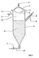
- the diaphragm pump has been represented, schematically and incompletely, by its diaphragm (I), the movement of which is ensured by a pressurized fluid introduced according to arrow (2) and limited by a seat (3) pierced with an opening (4).
- the capacity (5) according to the invention. It has a cylindrical-conical shape and is provided, on its side wall, with a nozzle (6) and a valve (7), intended for the evacuation of air, with a supply pipe (8). in suspension equipped with a valve (9), an evacuation pipe (10) equipped with a valve (11).
- the capacity is filled from top to bottom with a layer of clear liquid (12) and a suspension height (13).
- a 0 15 mm air bleed nozzle is placed at the seat.
- the pump is supplied with a suspension of resin grains having a specific mass of 1.140 g / l, in which the solid / liquid ratio is equal to I / 2 by volume.
- the pump generates a volume of 4 1 per cycle and is adjusted so as to perform 600 cycles / h at a regular rate.
- the interface between the clear liquid and the suspension is maintained at the side nozzle.
- the present invention applies to the treatment of suspensions in which the solid particles are fragile and denser than the liquid phase.
- Mention may in particular be made of the handling of grains of resins, ion exchangers, in fixing or elution installations in columns.
Landscapes
- Engineering & Computer Science (AREA)
- Mechanical Engineering (AREA)
- General Engineering & Computer Science (AREA)
- Reciprocating Pumps (AREA)
- Devices And Processes Conducted In The Presence Of Fluids And Solid Particles (AREA)
Applications Claiming Priority (2)
| Application Number | Priority Date | Filing Date | Title |
|---|---|---|---|
| FR8116667 | 1981-08-27 | ||
| FR8116667A FR2512123A1 (fr) | 1981-08-27 | 1981-08-27 | Pompe volumetrique a membrane pour suspensions de particules fragiles |
Publications (1)
| Publication Number | Publication Date |
|---|---|
| EP0074321A1 true EP0074321A1 (fr) | 1983-03-16 |
Family
ID=9261838
Family Applications (1)
| Application Number | Title | Priority Date | Filing Date |
|---|---|---|---|
| EP82420121A Withdrawn EP0074321A1 (fr) | 1981-08-27 | 1982-08-25 | Pompe volumétrique à membrane pour suspensions de particules fragiles |
Country Status (10)
| Country | Link |
|---|---|
| EP (1) | EP0074321A1 (enExample) |
| AU (1) | AU8773482A (enExample) |
| DK (1) | DK382582A (enExample) |
| ES (1) | ES515261A0 (enExample) |
| FI (1) | FI822968L (enExample) |
| FR (1) | FR2512123A1 (enExample) |
| GR (1) | GR76432B (enExample) |
| NO (1) | NO822895L (enExample) |
| OA (1) | OA07191A (enExample) |
| PT (1) | PT75468B (enExample) |
Cited By (1)
| Publication number | Priority date | Publication date | Assignee | Title |
|---|---|---|---|---|
| EP0343773A1 (en) * | 1988-03-23 | 1989-11-29 | Kabushiki Kaisha Little Rock | Fluid pump apparatus and valve device |
Citations (6)
| Publication number | Priority date | Publication date | Assignee | Title |
|---|---|---|---|---|
| DE251565C (enExample) * | ||||
| DE1103365B (de) * | 1957-03-21 | 1961-03-30 | Distillers Co Yeast Ltd | Vorrichtung zum Pumpen von leicht verdampfbaren Fluessigkeiten, insbesondere fluessiger Kohlensaeure |
| FR1421460A (fr) * | 1964-10-29 | 1965-12-17 | Minerais De L Ouest S I M O So | Dispositif pour la production d'impulsions de pression ou de mise à vide |
| FR1444747A (fr) * | 1965-03-30 | 1966-07-08 | Dosapro | Perfectionnements aux pompes, notamment aux pompes doseuses |
| FR2183868A1 (en) * | 1972-05-08 | 1973-12-21 | Imp Metal Ind Kynoch Ltd | Pressurizing system - for liquid metal with intermediate fluid sepg pressurized oil |
| FR2366195A1 (fr) * | 1976-10-04 | 1978-04-28 | Seureca | Procede et installation pour transporter un melange d'eau et de dechets |
-
1981
- 1981-08-27 FR FR8116667A patent/FR2512123A1/fr active Granted
-
1982
- 1982-08-20 OA OA57782A patent/OA07191A/xx unknown
- 1982-08-20 GR GR69068A patent/GR76432B/el unknown
- 1982-08-25 EP EP82420121A patent/EP0074321A1/fr not_active Withdrawn
- 1982-08-25 PT PT75468A patent/PT75468B/pt unknown
- 1982-08-26 DK DK382582A patent/DK382582A/da not_active Application Discontinuation
- 1982-08-26 ES ES515261A patent/ES515261A0/es active Granted
- 1982-08-26 AU AU87734/82A patent/AU8773482A/en not_active Abandoned
- 1982-08-26 FI FI822968A patent/FI822968L/fi not_active Application Discontinuation
- 1982-08-26 NO NO822895A patent/NO822895L/no unknown
Patent Citations (6)
| Publication number | Priority date | Publication date | Assignee | Title |
|---|---|---|---|---|
| DE251565C (enExample) * | ||||
| DE1103365B (de) * | 1957-03-21 | 1961-03-30 | Distillers Co Yeast Ltd | Vorrichtung zum Pumpen von leicht verdampfbaren Fluessigkeiten, insbesondere fluessiger Kohlensaeure |
| FR1421460A (fr) * | 1964-10-29 | 1965-12-17 | Minerais De L Ouest S I M O So | Dispositif pour la production d'impulsions de pression ou de mise à vide |
| FR1444747A (fr) * | 1965-03-30 | 1966-07-08 | Dosapro | Perfectionnements aux pompes, notamment aux pompes doseuses |
| FR2183868A1 (en) * | 1972-05-08 | 1973-12-21 | Imp Metal Ind Kynoch Ltd | Pressurizing system - for liquid metal with intermediate fluid sepg pressurized oil |
| FR2366195A1 (fr) * | 1976-10-04 | 1978-04-28 | Seureca | Procede et installation pour transporter un melange d'eau et de dechets |
Cited By (2)
| Publication number | Priority date | Publication date | Assignee | Title |
|---|---|---|---|---|
| EP0343773A1 (en) * | 1988-03-23 | 1989-11-29 | Kabushiki Kaisha Little Rock | Fluid pump apparatus and valve device |
| EP0390298A3 (en) * | 1988-03-23 | 1990-10-31 | Kabushiki Kaisha Little Rock | Fluid pump apparatus |
Also Published As
| Publication number | Publication date |
|---|---|
| ES8306225A1 (es) | 1983-05-01 |
| GR76432B (enExample) | 1984-08-10 |
| PT75468B (fr) | 1984-11-12 |
| FI822968A7 (fi) | 1983-02-28 |
| ES515261A0 (es) | 1983-05-01 |
| FR2512123B1 (enExample) | 1984-02-03 |
| NO822895L (no) | 1983-02-28 |
| OA07191A (fr) | 1984-04-30 |
| FI822968A0 (fi) | 1982-08-26 |
| PT75468A (fr) | 1982-09-01 |
| FR2512123A1 (fr) | 1983-03-04 |
| AU8773482A (en) | 1983-03-03 |
| FI822968L (fi) | 1983-02-28 |
| DK382582A (da) | 1983-02-28 |
Similar Documents
| Publication | Publication Date | Title |
|---|---|---|
| EP2499073B1 (fr) | Dispositif a fluidisation potentielle, destine au convoyage de materiaux pulverulents en lit hyperdense | |
| EP0190082B1 (fr) | Dispositif de distribution à débit régulé d'une matière pulvérulente fluidisable | |
| FR2470321A1 (fr) | Vanne | |
| WO1989000683A1 (fr) | Procede et dispositif de repartition d'un volume primaire de fluide en un nombre determine de volumes secondaires presentant une relation predefinie entre eux | |
| EP0074321A1 (fr) | Pompe volumétrique à membrane pour suspensions de particules fragiles | |
| CN1970130A (zh) | 液、液分离装置 | |
| FR2552751A1 (fr) | Appareil et procede de degazage d'un liquide, notamment de l'eau | |
| EP0562104B1 (fr) | Lit medical fluidise muni d'un dispositif d'evacuation de ses constituants granulaires souilles | |
| CN106641367A (zh) | 一种油水分离浮球阀 | |
| FR2583004A1 (fr) | Collecteur a carburant dispose dans un reservoir a carburant comme reserve de carburant de fonctionnement pour un moteur a combustion | |
| WO1995033102A1 (fr) | Equipement pour le remplissage et le vidage des reservoirs de chasse de wc | |
| FR2550957A1 (fr) | Dispositif d'alimentation de particules comportant une alimentation de reserve | |
| FR2670396A1 (fr) | Filtre pour machine-outil. | |
| FR2686840A1 (fr) | Dispositif d'aeration pour reservoir de carburant. | |
| CN115535942B (zh) | 液体食品生产用灌装装置 | |
| FR2495515A1 (fr) | Dispositif d'alimentation en plomb liquide de moules pour connexions de plaques de batteries d'accumulateurs au plomb | |
| FR2517211A1 (fr) | Perfectionnements aux epandeurs de poudre et notamment aux extincteurs | |
| EP0648523A1 (fr) | Dispositif et procédé de dégazage pour circuit hydraulique | |
| FR2547644A1 (fr) | Dispositif de lubrification d'air comprime | |
| FR2747607A1 (fr) | Cuve rigidifiee en matiere plastique et son procede de fabrication par rotomoulage | |
| BE1015406A3 (fr) | Procede et dispositif de recuperation d'un fluide contenu dans une epave. | |
| BE846103A (fr) | Purgeur automatique de gaz | |
| EP2474674B1 (fr) | Dispositif de siphon à amorçage automatique | |
| EP0450250A1 (fr) | Soupape à haute pression d'ouverture et fermeture par temps automatiques | |
| BE670582A (enExample) |
Legal Events
| Date | Code | Title | Description |
|---|---|---|---|
| PUAI | Public reference made under article 153(3) epc to a published international application that has entered the european phase |
Free format text: ORIGINAL CODE: 0009012 |
|
| AK | Designated contracting states |
Designated state(s): AT BE CH DE GB IT LI LU NL SE |
|
| 17P | Request for examination filed |
Effective date: 19830616 |
|
| RAP1 | Party data changed (applicant data changed or rights of an application transferred) |
Owner name: SOCIETE CENTRALE DE L'URANIUM ET DES MINERAIS ET M |
|
| STAA | Information on the status of an ep patent application or granted ep patent |
Free format text: STATUS: THE APPLICATION IS DEEMED TO BE WITHDRAWN |
|
| 18D | Application deemed to be withdrawn |
Effective date: 19850301 |
|
| ITF | It: translation for a ep patent filed | ||
| RIN1 | Information on inventor provided before grant (corrected) |
Inventor name: CAPITANI, ENZO |