EP0074321A1 - Diaphragm displacement pump for suspensions of fragile particles - Google Patents
Diaphragm displacement pump for suspensions of fragile particles Download PDFInfo
- Publication number
- EP0074321A1 EP0074321A1 EP82420121A EP82420121A EP0074321A1 EP 0074321 A1 EP0074321 A1 EP 0074321A1 EP 82420121 A EP82420121 A EP 82420121A EP 82420121 A EP82420121 A EP 82420121A EP 0074321 A1 EP0074321 A1 EP 0074321A1
- Authority
- EP
- European Patent Office
- Prior art keywords
- membrane
- capacity
- suspension
- pump
- pump according
- Prior art date
- Legal status (The legal status is an assumption and is not a legal conclusion. Google has not performed a legal analysis and makes no representation as to the accuracy of the status listed.)
- Withdrawn
Links
Images
Classifications
-
- F—MECHANICAL ENGINEERING; LIGHTING; HEATING; WEAPONS; BLASTING
- F04—POSITIVE - DISPLACEMENT MACHINES FOR LIQUIDS; PUMPS FOR LIQUIDS OR ELASTIC FLUIDS
- F04B—POSITIVE-DISPLACEMENT MACHINES FOR LIQUIDS; PUMPS
- F04B43/00—Machines, pumps, or pumping installations having flexible working members
- F04B43/02—Machines, pumps, or pumping installations having flexible working members having plate-like flexible members, e.g. diaphragms
- F04B43/06—Pumps having fluid drive
-
- F—MECHANICAL ENGINEERING; LIGHTING; HEATING; WEAPONS; BLASTING
- F04—POSITIVE - DISPLACEMENT MACHINES FOR LIQUIDS; PUMPS FOR LIQUIDS OR ELASTIC FLUIDS
- F04B—POSITIVE-DISPLACEMENT MACHINES FOR LIQUIDS; PUMPS
- F04B53/00—Component parts, details or accessories not provided for in, or of interest apart from, groups F04B1/00 - F04B23/00 or F04B39/00 - F04B47/00
- F04B53/14—Pistons, piston-rods or piston-rod connections
- F04B53/141—Intermediate liquid piston between the driving piston and the pumped liquid
Definitions
- the present invention relates to a positive displacement diaphragm pump, intended for the transfer of suspensions and, more particularly, of suspensions containing fragile particles.
- the diaphragm pump is one of the best means of transferring suspensions containing a high proportion of solids, such as thick sludge, from one point to another in an installation. , metallurgical concentrates, clays, pulp, pigments, etc ...
- This type of pump has, however, the disadvantage of being designed so that, during the delivery phase, the membrane strongly presses on the conveyed particles at the risk of crushing or breaking them if they do not have a resistance. sufficient mechanical.
- This pump comprises a membrane which separates a control compartment provided with means for displacing the membrane and a transfer compartment in which the suspension, under the effect of said displacement, is sucked from a supply pipe, then discharged to a evacuation pipe by means of non-return valves, and is characterized in that the transfer compartment is extended perpendicular to the plane of the membrane by an additional capacity, that the evacuation line is placed at the end of the capacity farthest from the membrane, than the line of feed is placed on the side wall of the capacity and its axis opens in a direction which moves away from the membrane at a point distant from the horizontal plane passing through the lowest level of the membrane.
- this pump comprises, like most of those of the prior art, a membrane arranged horizontally between two compartments.
- One is called the control compartment because it contains the working fluid which ensures the movement of the membrane; this fluid being a liquid or a gas under pressure which is introduced into the compartment via a valve whose opening is controlled by a timer.
- the other is called the transfer compartment, because it is connected to both the supply line and the discharge line, by means of non-return valves and ensures, under the effect of the displacement of the membrane, the passage of the suspension from one of these pipes to the other in the following way: when the membrane rises, from its low position, there is an increase in the volume of the transfer compartment, which causes a vacuum and, consequently, the opening of the supply valve and the closing of the discharge valve; an amount of suspension corresponding to the volume generated is thus introduced into the pump. Then, the membrane descends to its initial low position by exerting a pressure on the suspension which transmits it to the discharge valve and makes it open, and to the suction valve which closes; a suspension volume corresponding to the admitted volume is then discharged by the pump.
- the Applicant has modified these operating conditions, by extending the transfer compartment by an additional capacity on which the supply and evacuation pipes are placed so that the particles of the suspension are permanently separated from the entire surface of the membrane with a layer of clear liquid and can decant during the filling phase of the pump.
- the forms of the capacity can be any. However, a certain symmetry, with respect to the axis perpendicular to the membrane, is desirable.
- the generatrices of the lateral surface are preferably parallel to the axis of the membrane and rest on a contour director which can be square, rectangular, circular or other.
- the director - has the shape of a circle so as to give the capacity a cylindrical shape.
- the cylinder a section of contour close to that of the membrane.
- the capacity can have a variable height. However, to achieve the desired results, it is given a minimum value equal to three times the travel of the membrane in its center.
- the capacity supply channel generally opens via a non-return valve on the side wall of the capacity in a direction which moves away from the membrane and which preferably forms an angle with the vertical. less than 60 degrees.
- the axis of the pipe emerges, it is at a distance from the horizontal plane passing through the lowest level of the membrane equal to at least the stroke of the membrane between its extreme positions.
- the evacuation pipe is connected via a non-return valve, at the end of the container furthest from the mem brane, so as to allow a better flow of the particles.
- the diameter of the two pipes depends on the suspension flows treated and, also, on the dimensions of the pump.
- This filling can be done by means of deionized water or suspension, which is carefully allowed to decant so as to form, on contact with the membrane, a layer of clear liquid.
- the solid particles of higher density than the liquid, flow down the capacity, while the liquid phase floats or not mixed with the water previously introduced. In the capacity is therefore a volume of suspension surmounted by a volume of clear liquid.
- the membrane When the membrane descends, it exerts its pressure on the particles via the volume of clear liquid, which causes the opening of the discharge valve and the evacuation of a volume of suspension corresponding to the volume displaced by the membrane. Then, the membrane rises again, allowing the introduction of a new volume of suspension isolated from the membrane by the volume of clear liquid.
- the particles are never subjected directly to direct contact with the membrane and any risk of degradation of the particles is eliminated.
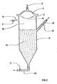
- the diaphragm pump has been represented, schematically and incompletely, by its diaphragm (I), the movement of which is ensured by a pressurized fluid introduced according to arrow (2) and limited by a seat (3) pierced with an opening (4).
- the capacity (5) according to the invention. It has a cylindrical-conical shape and is provided, on its side wall, with a nozzle (6) and a valve (7), intended for the evacuation of air, with a supply pipe (8). in suspension equipped with a valve (9), an evacuation pipe (10) equipped with a valve (11).
- the capacity is filled from top to bottom with a layer of clear liquid (12) and a suspension height (13).
- a 0 15 mm air bleed nozzle is placed at the seat.
- the pump is supplied with a suspension of resin grains having a specific mass of 1.140 g / l, in which the solid / liquid ratio is equal to I / 2 by volume.
- the pump generates a volume of 4 1 per cycle and is adjusted so as to perform 600 cycles / h at a regular rate.
- the interface between the clear liquid and the suspension is maintained at the side nozzle.
- the present invention applies to the treatment of suspensions in which the solid particles are fragile and denser than the liquid phase.
- Mention may in particular be made of the handling of grains of resins, ion exchangers, in fixing or elution installations in columns.
Landscapes
- Engineering & Computer Science (AREA)
- Mechanical Engineering (AREA)
- General Engineering & Computer Science (AREA)
- Reciprocating Pumps (AREA)
- Devices And Processes Conducted In The Presence Of Fluids And Solid Particles (AREA)
Abstract
Description
La présente invention concerne une pompe volumétrique à membrane, destinée au transfert de suspensions et, plus particulièrement, de suspensions contenant des particules fragiles.The present invention relates to a positive displacement diaphragm pump, intended for the transfer of suspensions and, more particularly, of suspensions containing fragile particles.
L'homme de l'art sait que la pompe à membrane constitue l'un des meilleurs moyens pour transférer d'un point à un autre d'une installation des suspensions contenant une forte proportion de solides, comme, par exemple, les boues épaisses, les concentrés métallurgiques, les argiles, les pâtes à papier, les pigments, etc...Those skilled in the art know that the diaphragm pump is one of the best means of transferring suspensions containing a high proportion of solids, such as thick sludge, from one point to another in an installation. , metallurgical concentrates, clays, pulp, pigments, etc ...
Ce genre de pompe présente, cependant, l'inconvénient d'être conçue de façon que, durant la phase de refoulement, la membrane appuie fortement sur les particules véhiculées au risque de les écraser ou de les briser si elles n'ont pas une résistance mécanique suffisante.This type of pump has, however, the disadvantage of being designed so that, during the delivery phase, the membrane strongly presses on the conveyed particles at the risk of crushing or breaking them if they do not have a resistance. sufficient mechanical.
Certes, pour la plupart des produits transportés, le maintien de l'intégrité physique des particules ne pose pas de problème en raison, soit de leur bonne tenue à la compression, ou parce qu'une modification de leur forme ou de leur état de division n'a aucune importance.Admittedly, for most of the products transported, the maintenance of the physical integrity of the particles poses no problem due either to their good resistance to compression, or because a modification of their shape or of their state of division. doesn't matter.
Cependant, il n'en va pas de même lorsqu'il s'agit de suspensions contenant des particules fragiles telles que des grains de résines échangeuses d'ions qui doivent être traitées avec ménagement pour éviter la formation de fines préjudiciables à leur durée de vie et au fonctionnement des colonnes qu'ils garnissent.However, this is not the case when it comes to suspensions containing fragile particles such as grains of ion exchange resins which must be treated with care to avoid the formation of fines which are detrimental to their service life. and the operation of the columns they line.
C'est pourquoi, la demanderesse a cherché et mis au point une pompe dans laquelle on empêche la dégradation des grains fragiles de la suspension véhiculée.This is why the applicant has sought and developed a pump in which the degradation of the fragile grains of the transported suspension is prevented.
Cette pompe comporte une membrane qui sépare un compartiment de commande muni de moyens de déplacement de la membrane et un compartiment de transfert dans lequel la suspension, sous l'effet dudit déplacement, est aspirée d'une canalisation d'alimentation, puis refoulée vers une canalisation d'évacuation par l'intermédiaire de clapets anti-retour, et se caractérise en ce que le compartiment de transfert est prolongé perpendiculairement au plan de la membrane par une capacité additionnelle, que la canalisation d'évacuation est placée à l'extrémité de la capacité la plus éloignée de la membrane, que la canalisation d'alimentation est placée sur la paroi latérale de la capacité et que son axe débouche suivant une direction qui s'éloigne de la membrane en un point distant du plan horizontal passant par le niveau le plus bas de la membrane.This pump comprises a membrane which separates a control compartment provided with means for displacing the membrane and a transfer compartment in which the suspension, under the effect of said displacement, is sucked from a supply pipe, then discharged to a evacuation pipe by means of non-return valves, and is characterized in that the transfer compartment is extended perpendicular to the plane of the membrane by an additional capacity, that the evacuation line is placed at the end of the capacity farthest from the membrane, than the line of feed is placed on the side wall of the capacity and its axis opens in a direction which moves away from the membrane at a point distant from the horizontal plane passing through the lowest level of the membrane.
Ainsi, cette pompe comporte, comme la plupart de celles de l'art antérieur, une membrane disposée horizontalement entre deux compartiments. L'un est dit compartiment de commande parce qu'il renferme le fluide moteur qui assure le déplacement de la membrane; ce fluide étant un liquide ou un gaz sous pression qui est introduit dans le compartiment par l'intermédiaire d'une vanne dont l'ouverture est contrôlée par une minuterie.Thus, this pump comprises, like most of those of the prior art, a membrane arranged horizontally between two compartments. One is called the control compartment because it contains the working fluid which ensures the movement of the membrane; this fluid being a liquid or a gas under pressure which is introduced into the compartment via a valve whose opening is controlled by a timer.
L'autre est appelé compartiment de transfert, car il est en liaison à la fois avec la canalisation d'alimentation et la canalisation d'évacuation, par l'intermédiaire de clapets anti-retour et assure, sous l'effet du déplacement de la membrane, le passage de la suspension de l'une de ces canalisation à l'autre de la manière suivante : lorsque la membrane s'élève, à partir de sa position basse, il y a accroissement du volume du compartiment de transfert, qui provoque une dépression et, par suite, l'ouverture du clapet d'alimentation et la fermeture du clapet de refoulement; une quantité de suspension correspondant au volume généré est ainsi introduite dans la pompe. Puis, la membrane redescend jusqu'à sa position basse initiale en exerçant une pression sur la suspension qui la transmet au clapet de refoulement et le fait s'ouvrir, et au clapet d'aspiration qui se ferme; un volume de suspension correspondant au volume admis est alors refoulé par la pompe.The other is called the transfer compartment, because it is connected to both the supply line and the discharge line, by means of non-return valves and ensures, under the effect of the displacement of the membrane, the passage of the suspension from one of these pipes to the other in the following way: when the membrane rises, from its low position, there is an increase in the volume of the transfer compartment, which causes a vacuum and, consequently, the opening of the supply valve and the closing of the discharge valve; an amount of suspension corresponding to the volume generated is thus introduced into the pump. Then, the membrane descends to its initial low position by exerting a pressure on the suspension which transmits it to the discharge valve and makes it open, and to the suction valve which closes; a suspension volume corresponding to the admitted volume is then discharged by the pump.
Ainsi, chaque cycle complet de la membrane correspond au transfert d'un volume déterminé de suspension, c'est pourquoi, on qualifie ces pompes de"volumétriques".Thus, each complete cycle of the membrane corresponds to the transfer of a determined volume of suspension, this is why, these pumps are called "volumetric".
Dans ces conditions de fonctionnement, on peut remarquer que rien n'empêche les particules de la suspension de venir en contact avec la membrane et de subir, de ce fait, un effet de choc lorsque cette dernière redescend, d'où peut résulter une désagrégation plus ou moins grande des particules.Under these operating conditions, we can notice that nothing fishes the particles of the suspension to come into contact with the membrane and to undergo, as a result, a shock effect when the latter descends, from which may result a more or less great disintegration of the particles.
La demanderesse a modifié ces conditions de marche, en prolongeant le compartiment de transfert par une capacité additionnelle sur laquelle les canalisations d'alimentation et d'évacuation sont placées de manière telle que les particules de la suspension sont en permanence séparées de la surface entière de la membrane par une couche de liquide clair et puissent décanter durant la phase de remplissage de la pompe.The Applicant has modified these operating conditions, by extending the transfer compartment by an additional capacity on which the supply and evacuation pipes are placed so that the particles of the suspension are permanently separated from the entire surface of the membrane with a layer of clear liquid and can decant during the filling phase of the pump.
Les formes de la capacité peuvent être quelconques. Toutefois, une certaine symétrie, par rapport à l'axe perpendiculaire à la membrane, est souhaitable. C'est ainsi que les génératrices de la surface latérale sont, de préférence, parallèles à l'axe de la membrane et s'appuient sur une directrice de contour pouvant être carré, rectangulaire, circulaire ou autre. Pour des raisons de commodité de montage, la membrane étant généralement un disque, la directrice--a la forme d'un cercle de manière à donner à la capacité une forme cylindrique. De plus, il est possible de donner au cylindre une section de contour voisin de celui de la membrane. La capacité peut avoir une hauteur variable. Toutefois, pour atteindre les résultats recherchés, on lui donne une valeur minimum égale à trois fois la course de la membrane en son centre.The forms of the capacity can be any. However, a certain symmetry, with respect to the axis perpendicular to the membrane, is desirable. Thus, the generatrices of the lateral surface are preferably parallel to the axis of the membrane and rest on a contour director which can be square, rectangular, circular or other. For reasons of assembly convenience, the membrane generally being a disc, the director - has the shape of a circle so as to give the capacity a cylindrical shape. In addition, it is possible to give the cylinder a section of contour close to that of the membrane. The capacity can have a variable height. However, to achieve the desired results, it is given a minimum value equal to three times the travel of the membrane in its center.
Le canal d'alimentation de la capacité débouche généralement par l'intermédiaire d'un clapet anti-retour sur la paroi latérale de la capacité suivant une direction qui s'éloigne de la membrane et qui forme, de préférence, avec la verticale un angle inférieur à 60 degrés.The capacity supply channel generally opens via a non-return valve on the side wall of the capacity in a direction which moves away from the membrane and which preferably forms an angle with the vertical. less than 60 degrees.
En ce qui concerne le point où débouche l'axe de la canalisation, il se trouve à une distance du plan horizontal passant par le niveau le plus bas de la membrane égale à au moins la course de la membrane entre ses positions extrêmes.With regard to the point where the axis of the pipe emerges, it is at a distance from the horizontal plane passing through the lowest level of the membrane equal to at least the stroke of the membrane between its extreme positions.
La canalisation d'évacuation est reliée par l'intermédiaire d'un clapet anti-retour, à l'extrémité de la capacité la plus éloignée de la membrane, de manière à permettre un meilleur écoulement des particules.The evacuation pipe is connected via a non-return valve, at the end of the container furthest from the mem brane, so as to allow a better flow of the particles.
Le diamètre des deux canalisations est fonction des débits de suspension traités et, aussi, des dimensions de la pompe.The diameter of the two pipes depends on the suspension flows treated and, also, on the dimensions of the pump.
Au démarrage de l'installation, il est nécessaire de remplir correctement la capacité et, donc, de pouvoir évacuer l'air qui ne peut s'échapper par refoulement; un piquage de mise à l'air équipé d'une vanne a été placé sur la paroi latérale de la capacité près de la membrane pour réaliser cette fonction.At the start of the installation, it is necessary to correctly fill the capacity and, therefore, to be able to evacuate the air which cannot escape by discharge; a vent connection fitted with a valve was placed on the side wall of the tank near the membrane to perform this function.
Ce remplissage peut être fait au moyen d'eau désionisée ou de suspension, qu'on laisse soigneusement décanter de manière à former, au contact de la membrane, une couche de liquide clair.This filling can be done by means of deionized water or suspension, which is carefully allowed to decant so as to form, on contact with the membrane, a layer of clear liquid.
En fonctionnement, lorsque la membrane s'élève, elle crée un espace libre immédiatement rempli par un volume correspondant de suspension.In operation, when the membrane rises, it creates a free space immediately filled with a corresponding volume of suspension.
Les particules solides, de densité plus élevée que le liquide, s'écoulent vers le bas de la capacité, tandis que la phase liquide surnage mélangée ou non avec l'eau préalablement introduite. Dans la capacité se trouve donc un volume de suspension surmonté d'un volume de liquide clair.The solid particles, of higher density than the liquid, flow down the capacity, while the liquid phase floats or not mixed with the water previously introduced. In the capacity is therefore a volume of suspension surmounted by a volume of clear liquid.
Lorsque la membrane redescend, elle exerce sa pression sur les particules par l'intermédiaire du volume de liquide clair, ce qui provoque l'ouverture du clapet de refoulement et l'évacuation d'un volume de suspension correspondant au volume déplacé par la membrane. Puis, la membrane s'élève à nouveau, permettant l'introduction d'un nouveau volume de suspension isolé de la membrane par le volume de liquide clair. Ainsi, les particules ne sont jamais sousmises directement à un contact direct avec la membrane et tout risque de dégradation des particules est supprimé.When the membrane descends, it exerts its pressure on the particles via the volume of clear liquid, which causes the opening of the discharge valve and the evacuation of a volume of suspension corresponding to the volume displaced by the membrane. Then, the membrane rises again, allowing the introduction of a new volume of suspension isolated from the membrane by the volume of clear liquid. Thus, the particles are never subjected directly to direct contact with the membrane and any risk of degradation of the particles is eliminated.
L'invention sera mieux comprise à l'aide du dessin ci-joint.The invention will be better understood using the attached drawing.
On a représenté, de façon schématique et incomplète, la pompe à membrane par sa membrane (I), dont le mouvement est assuré par un fluide sous pression introduit suivant la flèche (2) et limité par un siège (3) percé d'une ouverture (4). En-dessous du siège se trouve la capacité (5) suivant l'invention. Elle a une forme cylindroconique et est munie, sur sa paroi latérale, d'un piquage (6) et d'une vanne (7), destinés à l'évacuation de l'air, d'une canalisation d'alimentation(8) en suspension équipée d'un clapet (9), d'une canalisation d'évacuation (10) équipée d'un clapet (11).The diaphragm pump has been represented, schematically and incompletely, by its diaphragm (I), the movement of which is ensured by a pressurized fluid introduced according to arrow (2) and limited by a seat (3) pierced with an opening (4). Below the seat is the capacity (5) according to the invention. It has a cylindrical-conical shape and is provided, on its side wall, with a nozzle (6) and a valve (7), intended for the evacuation of air, with a supply pipe (8). in suspension equipped with a valve (9), an evacuation pipe (10) equipped with a valve (11).
La capacité est remplie du haut en bas par une couche de liquide clair (12) et une hauteur de suspension (13).The capacity is filled from top to bottom with a layer of clear liquid (12) and a suspension height (13).
L'invention peut être illustrée au moyen de l'exemple d'application suivant : une pompe ayant une membrane en néoprène, de diamètre 400 mm, un siège percé d'une ouverture circulaire de φ 100 mm, fonctionnant avec une source d'air comprimé à 6 bar, a été équipée avec une capacité cylindroconique, ayant un diamètre voisin de celui de la membrane, une hauteur cylindrique de 500 mm, une hauteur conique de 300 mm, munie de deux canalisations de 0 100 mm, l'une d'alimentation inclinée de 60° par rapport à la verticale et dont l'axe débouche à 300 mm du plan passant par le niveau le plus bas de la membrane, l'autre verticale située à la base du cône. Un piquage de purge d'air de 0 15 mm est placé au niveau du siège.The invention can be illustrated by means of the following application example: a pump having a neoprene membrane, 400 mm in diameter, a seat pierced with a circular opening of φ 100 mm, operating with an air source compressed to 6 bar, was equipped with a cylindrical-conical capacity, having a diameter close to that of the membrane, a cylindrical height of 500 mm, a conical height of 300 mm, provided with two pipes of 0 100 mm, one of feed inclined 60 ° to the vertical and whose axis opens 300 mm from the plane passing through the lowest level of the membrane, the other vertical located at the base of the cone. A 0 15 mm air bleed nozzle is placed at the seat.
La pompe est alimentée avec une suspension de grains de résines ayant une masse spécifique de 1.140 g/1, dans laquelle le rapport solide/li- quide est égal à I/2 en volume. La pompe génère un volume de 4 1 par cycle et est réglée de manière à effectuer 600 cycles/h suivant un rythme régulier. L'interface entre le liquide clair et la suspension se maintient au niveau du piquage latéral.The pump is supplied with a suspension of resin grains having a specific mass of 1.140 g / l, in which the solid / liquid ratio is equal to I / 2 by volume. The pump generates a volume of 4 1 per cycle and is adjusted so as to perform 600 cycles / h at a regular rate. The interface between the clear liquid and the suspension is maintained at the side nozzle.
On constate que le pourcentage de fines dans la suspension, avant et après passage dans la pompe, ne subit aucune évolution.It can be seen that the percentage of fines in the suspension, before and after passage through the pump, does not undergo any change.
La présente invention s'applique au traitement de suspensions dans lesquelles les particules solides sont fragiles et plus denses que la phase liquide.The present invention applies to the treatment of suspensions in which the solid particles are fragile and denser than the liquid phase.
On peut citer, en particulier, la manutention des grains de résines, échangeuses d'ions, dans les installations de fixation ou d'élution en colonnes.Mention may in particular be made of the handling of grains of resins, ion exchangers, in fixing or elution installations in columns.
Claims (5)
Applications Claiming Priority (2)
| Application Number | Priority Date | Filing Date | Title |
|---|---|---|---|
| FR8116667A FR2512123A1 (en) | 1981-08-27 | 1981-08-27 | MEMBRANE VOLUMETRIC PUMP FOR FRAGILE PARTICLE SUSPENSIONS |
| FR8116667 | 1981-08-27 |
Publications (1)
| Publication Number | Publication Date |
|---|---|
| EP0074321A1 true EP0074321A1 (en) | 1983-03-16 |
Family
ID=9261838
Family Applications (1)
| Application Number | Title | Priority Date | Filing Date |
|---|---|---|---|
| EP82420121A Withdrawn EP0074321A1 (en) | 1981-08-27 | 1982-08-25 | Diaphragm displacement pump for suspensions of fragile particles |
Country Status (10)
| Country | Link |
|---|---|
| EP (1) | EP0074321A1 (en) |
| AU (1) | AU8773482A (en) |
| DK (1) | DK382582A (en) |
| ES (1) | ES8306225A1 (en) |
| FI (1) | FI822968L (en) |
| FR (1) | FR2512123A1 (en) |
| GR (1) | GR76432B (en) |
| NO (1) | NO822895L (en) |
| OA (1) | OA07191A (en) |
| PT (1) | PT75468B (en) |
Cited By (1)
| Publication number | Priority date | Publication date | Assignee | Title |
|---|---|---|---|---|
| EP0343773A1 (en) * | 1988-03-23 | 1989-11-29 | Kabushiki Kaisha Little Rock | Fluid pump apparatus and valve device |
Citations (6)
| Publication number | Priority date | Publication date | Assignee | Title |
|---|---|---|---|---|
| DE251565C (en) * | ||||
| DE1103365B (en) * | 1957-03-21 | 1961-03-30 | Distillers Co Yeast Ltd | Device for pumping easily vaporizable liquids, especially liquid carbonic acid |
| FR1421460A (en) * | 1964-10-29 | 1965-12-17 | Minerais De L Ouest S I M O So | Device for generating pressure or vacuum pulses |
| FR1444747A (en) * | 1965-03-30 | 1966-07-08 | Dosapro | Improvements to pumps, particularly metering pumps |
| FR2183868A1 (en) * | 1972-05-08 | 1973-12-21 | Imp Metal Ind Kynoch Ltd | Pressurizing system - for liquid metal with intermediate fluid sepg pressurized oil |
| FR2366195A1 (en) * | 1976-10-04 | 1978-04-28 | Seureca | Domestic waste disposal system - uses pressurised water to transport waste from individual collector tanks to main treatment tank |
-
1981
- 1981-08-27 FR FR8116667A patent/FR2512123A1/en active Granted
-
1982
- 1982-08-20 GR GR69068A patent/GR76432B/el unknown
- 1982-08-20 OA OA57782A patent/OA07191A/en unknown
- 1982-08-25 PT PT75468A patent/PT75468B/en unknown
- 1982-08-25 EP EP82420121A patent/EP0074321A1/en not_active Withdrawn
- 1982-08-26 DK DK382582A patent/DK382582A/en not_active Application Discontinuation
- 1982-08-26 ES ES515261A patent/ES8306225A1/en not_active Expired
- 1982-08-26 FI FI822968A patent/FI822968L/en not_active Application Discontinuation
- 1982-08-26 NO NO822895A patent/NO822895L/en unknown
- 1982-08-26 AU AU87734/82A patent/AU8773482A/en not_active Abandoned
Patent Citations (6)
| Publication number | Priority date | Publication date | Assignee | Title |
|---|---|---|---|---|
| DE251565C (en) * | ||||
| DE1103365B (en) * | 1957-03-21 | 1961-03-30 | Distillers Co Yeast Ltd | Device for pumping easily vaporizable liquids, especially liquid carbonic acid |
| FR1421460A (en) * | 1964-10-29 | 1965-12-17 | Minerais De L Ouest S I M O So | Device for generating pressure or vacuum pulses |
| FR1444747A (en) * | 1965-03-30 | 1966-07-08 | Dosapro | Improvements to pumps, particularly metering pumps |
| FR2183868A1 (en) * | 1972-05-08 | 1973-12-21 | Imp Metal Ind Kynoch Ltd | Pressurizing system - for liquid metal with intermediate fluid sepg pressurized oil |
| FR2366195A1 (en) * | 1976-10-04 | 1978-04-28 | Seureca | Domestic waste disposal system - uses pressurised water to transport waste from individual collector tanks to main treatment tank |
Cited By (3)
| Publication number | Priority date | Publication date | Assignee | Title |
|---|---|---|---|---|
| EP0343773A1 (en) * | 1988-03-23 | 1989-11-29 | Kabushiki Kaisha Little Rock | Fluid pump apparatus and valve device |
| EP0390298A2 (en) * | 1988-03-23 | 1990-10-03 | Kabushiki Kaisha Little Rock | Fluid pump apparatus |
| EP0390298A3 (en) * | 1988-03-23 | 1990-10-31 | Kabushiki Kaisha Little Rock | Fluid pump apparatus |
Also Published As
| Publication number | Publication date |
|---|---|
| PT75468B (en) | 1984-11-12 |
| ES515261A0 (en) | 1983-05-01 |
| FI822968L (en) | 1983-02-28 |
| DK382582A (en) | 1983-02-28 |
| PT75468A (en) | 1982-09-01 |
| NO822895L (en) | 1983-02-28 |
| FR2512123A1 (en) | 1983-03-04 |
| ES8306225A1 (en) | 1983-05-01 |
| FR2512123B1 (en) | 1984-02-03 |
| AU8773482A (en) | 1983-03-03 |
| GR76432B (en) | 1984-08-10 |
| FI822968A0 (en) | 1982-08-26 |
| OA07191A (en) | 1984-04-30 |
Similar Documents
| Publication | Publication Date | Title |
|---|---|---|
| EP2499073B1 (en) | Potential fluidization device for conveying powder materials onto a hyperdense bed | |
| EP0190082B1 (en) | Distribution device with a controlled flow for fluidizable bulk material | |
| EP0298872B1 (en) | Process and apparatus for dividing a primary volume of fluid into a certain number of secundary volumes having a predetermined ratio | |
| WO2018189447A1 (en) | Liquid double distribution device of use in particular in an apparatus in which a liquid phase flows under gravity | |
| EP0074321A1 (en) | Diaphragm displacement pump for suspensions of fragile particles | |
| CN106641367A (en) | Float valve for oil-water separation | |
| FR2583004A1 (en) | FUEL COLLECTOR ARRANGED IN A FUEL TANK AS AN OPERATING FUEL RESERVE FOR A COMBUSTION ENGINE | |
| EP0562104B1 (en) | Fluidized medical bed equipped with a device for eliminating soiled granular constituents | |
| FR2587813A1 (en) | Level-adjusting device for a liquid container | |
| FR2550957A1 (en) | PARTICLE FEEDING DEVICE HAVING RESERVE FEEDING | |
| EP1129968B1 (en) | Adjustable device for transferring by gravity pulverulent or granular material | |
| FR2579681A1 (en) | Improvements to devices of the bell type, intended for collecting wave energy | |
| FR2495515A1 (en) | Dosing valve for adding molten lead to moulds - for making connections to the plates of lead accumulators | |
| BE1015406A3 (en) | Method and device for content in a fluid recovery wreck. | |
| EP0450250A1 (en) | High pressure valve with automatic timing for opening and closing | |
| BE670582A (en) | ||
| FR2547644A1 (en) | Compressed air lubrication device | |
| FR2517211A1 (en) | Powder discharge fire extinguisher - has selected outlet cone angle ensuring complete powder discharge and constant gas outlet pressure valve | |
| FR2747607A1 (en) | Large plastic container, e.g. for fuel tank or septic tank | |
| FR3128746A1 (en) | UNDERWATER COMPRESSED AIR STORAGE DEVICE OBTAINED BY A HYDRAULIC PUMP | |
| FR2949448A1 (en) | Hopper device for storage of pellets, has tank closed superiorly by horizontal wall and provided with loading box arranged for generating flow of bulk materials describing curve leading to lower end of conical base of tank | |
| EP2474674B1 (en) | Siphon device with automatic priming | |
| FR2711322A1 (en) | Device and degassing method for hydraulic circuit. | |
| FR2852944A1 (en) | Container e.g. bottle, filling procedure, involves establishing fluidic communication between cavity of tank and container, and allowing liquid to flow from cavity to container | |
| CA2193771A1 (en) | Inclined separation tank |
Legal Events
| Date | Code | Title | Description |
|---|---|---|---|
| PUAI | Public reference made under article 153(3) epc to a published international application that has entered the european phase |
Free format text: ORIGINAL CODE: 0009012 |
|
| AK | Designated contracting states |
Designated state(s): AT BE CH DE GB IT LI LU NL SE |
|
| 17P | Request for examination filed |
Effective date: 19830616 |
|
| RAP1 | Party data changed (applicant data changed or rights of an application transferred) |
Owner name: SOCIETE CENTRALE DE L'URANIUM ET DES MINERAIS ET M |
|
| STAA | Information on the status of an ep patent application or granted ep patent |
Free format text: STATUS: THE APPLICATION IS DEEMED TO BE WITHDRAWN |
|
| 18D | Application deemed to be withdrawn |
Effective date: 19850301 |
|
| ITF | It: translation for a ep patent filed |
Owner name: RIT.TO ALL'OEB ALLO STATO DI DOMANDA;FUMERO BREVET |
|
| RIN1 | Information on inventor provided before grant (corrected) |
Inventor name: CAPITANI, ENZO |