EP0074142A2 - Circuit arrangement for receiving two modulated signals, especially in television - Google Patents
Circuit arrangement for receiving two modulated signals, especially in television Download PDFInfo
- Publication number
- EP0074142A2 EP0074142A2 EP82201071A EP82201071A EP0074142A2 EP 0074142 A2 EP0074142 A2 EP 0074142A2 EP 82201071 A EP82201071 A EP 82201071A EP 82201071 A EP82201071 A EP 82201071A EP 0074142 A2 EP0074142 A2 EP 0074142A2
- Authority
- EP
- European Patent Office
- Prior art keywords
- signal
- signals
- amplifier
- stereo
- circuit arrangement
- Prior art date
- Legal status (The legal status is an assumption and is not a legal conclusion. Google has not performed a legal analysis and makes no representation as to the accuracy of the status listed.)
- Granted
Links
Images
Classifications
-
- H—ELECTRICITY
- H04—ELECTRIC COMMUNICATION TECHNIQUE
- H04N—PICTORIAL COMMUNICATION, e.g. TELEVISION
- H04N5/00—Details of television systems
- H04N5/44—Receiver circuitry for the reception of television signals according to analogue transmission standards
- H04N5/60—Receiver circuitry for the reception of television signals according to analogue transmission standards for the sound signals
- H04N5/607—Receiver circuitry for the reception of television signals according to analogue transmission standards for the sound signals for more than one sound signal, e.g. stereo, multilanguages
Definitions
- the invention relates to a circuit arrangement for receiving two modulation signals, in particular in television, in which the first modulation signal, for example the stereo sum signal (L + R) or a first audio signal, on a first carrier and the second modulation signal (K 2 ),
- the first modulation signal for example the stereo sum signal (L + R) or a first audio signal
- the second modulation signal K 2
- the right signal (2R) or a second sound signal are transmitted on a second carrier, the left signal being formed from the two modulation signals by means of an adding or subtracting stage in the case of stereo reception, and the gain for the sum signal being higher by a factor of 2 than for the right signal and the gain for two modulation signals is the same for two-tone reception.
- the first modulation signal K 1 on the first carrier and the second modulation signal K 2 on the second carrier are transmitted next to one another in terms of frequency, preferably in frequency modulation.
- the two modulation signals can contain different information, for example in different languages, and can alternatively be processed further. They can also belong to a stereo signal, for example the signal K 1 containing the sum (L + R) of the left information and the right information, while the modulation signal K 2 contains the double right information (2R).
- a correction by a factor of 2 and then a difference must be made on the one hand, the amplitudes being matched as precisely as possible in order to avoid crosstalk as far as possible.
- the invention has for its object to make the adjustment for difference formation (dematriculation) independent of the type of external wiring and outside the signal path, e.g. by means of a direct current setting value.
- each of the two signals is routed via an amplifier with adjustable amplification, the amplification degree of the amplifier being adjustable in opposite directions for optimal dematrification of the stereo signal and for two-tone reception a factor of 2 can be switched.
- the degree of amplification of the amplifiers can also be set in the same direction, so that a volume setting can be carried out.
- the minimum of crosstalk will only be achieved for a certain volume. But for simpler circuit concepts with lower quality requirements, a desirable reduction in effort can result.
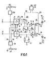
- the modulation signals K 1 and K 2 demodulated by the carrier are fed to input terminals 1 and 2 and fed to the inputs of two adjustable amplifiers 3 and 4.
- the output 5 of the amplifier 3 is connected to a deemphasis element 6 and the input of an impedance converter 7, the output of which is connected to the first input terminal 8 of a modulation type selector switch 10.
- An output 9 of the amplifier 4 is connected to a second de-emphasis element 11 to earth and to the input of a second impedance converter 12, the output of which is connected to the second input terminal 13 of the modulation type selector switch 10.
- the loudspeakers 19 and 20 are connected to the output terminals 15 and 16 of the modulation type selector switch 10 via further signal processing circuits, for example amplifiers 17 and 18, respectively.
- the switch 10 is a four-stage switch, the contacts of which are connected in a known manner so that - counted from above - the signals from the input terminals 8 and 13 arrive separately at the speakers 19 and 20 in the first position shown. In the second position, they are fed together by terminal 8 for the monoaural reproduction of a stereophonic signal. In the third position, the same connection is provided in order to make the information signal K 1 , which corresponds, for example, to the original language of a film, audible via both loudspeakers 19 and 20.
- the signal K 2 is fed from the terminal 13 to both speakers, for example for playback in another language.
- the two changeover switches the tongue of which is located at the output terminals 15 and 16, are actuated by means of an actuation switch 21 which can be brought into one of the four positions by means of a rotary knob 22.
- the effect of this switch 21 is shown by the dashed line 23 to the changeover zones of the changeover switches 15 and 16.
- the actuation switch 21 can also be designed as an electronic control.
- a signal is fed from the output 24 of the amplifier 4 via a switch 25 to the input of the impedance converter 7 in such a way that at point A the difference between the signals from the output 5 of the amplifier 3 and the signal from the output 24 of the amplifier 4 is formed.
- the degree of gain must be adjusted; for this purpose, a connection is established between the outputs 27 and 28 of the amplifier 3 by means of a changeover switch 29 such that the gain is increased by a factor of 2. It would of course also be possible to reduce the amplification of the amplifier 4 to 0.5 in a corresponding manner by means of a changeover switch.
- the changeover switches 25 and 29 are brought into the required position by the actuating switch 21 via an operative connection 30. As you can see, these switches are only closed with stereo reception; for the other types of reception, the gain is not changed and the signals are not dematriated.
- the amplifiers 3 and 4 are designed as cross-coupled differential amplifiers in such a way that the gain can be changed at their control inputs 31 and 32 by means of direct voltages or direct currents.
- These DC control variables are supplied by the outputs 33 and 34 of a differential amplifier 36, the input of which is taken from the tap of a potentiometer 37 connected between the supply source + U and ground.
- the output values of the differential amplifier 36 change in opposite directions, and accordingly the amplification levels of the amplifiers 3 and 4 are changed in opposite directions.
- the amplifiers 3 and 4 also have inputs 37 and 38 which are connected to one another and to the output of a direct current amplifier 39.
- the input of the amplifier 39 is connected to the tap of a potentiometer 40 connected between ground and + U B. By adjusting this tap, the amplification of the amplifiers 3 and 4 can be changed in the same direction. This enables the level to be adjusted for both transmission channels. If necessary, adjustment of the potentiometer 40 can also be used to adjust the volume.
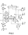
- Strength in F. 2 shows the block diagram according to FIG. 1 with some further details, the same parts being provided with the same reference numerals.
- the switch 10 with the downstream connections to the speakers has been omitted.
- the output 5 of the amplifier 3 controls a current mirror circuit 41
- the output 9 of the amplifier 4 controls a current mirror circuit 42.
- the output of the current mirror circuit 41 is connected to a current node B, which is located at the input of the impedance converter 7.
- a first output 45 of the current mirror circuit 42 is connected to the input of the impedance converter 12.
- a second output 46 of the current mirror circuit 42 is connected via a switch 43 to the input of a third current mirror circuit 44, the output of which is also at the node B and thus at the input of the impedance converter 7.
- the impedance converter 7 with the de-emphasis element 6 connected is thus supplied with a signal which corresponds to the difference between the stereo signals 2 (L + R) and 2R, that is to say 2L.
- the amplifiers 3 and 4 have the same amplification except for slight differences due to the adjustment; likewise, the ratio between the input current and the output current of the current mirrors 41, 42 and 44 is normally the same.
- the signal K is also transmitted from the output terminal 9 via the current mirror circuits 42 and 44 to the node B, the desired dematrification taking place.
- the amplifiers 3 and 4 are therefore not switched over for the factor 2 mentioned, but this adaptation takes place within a current mirror circuit 41 which is provided anyway for signal transmission and decoupling from the output.
- the switch 43 is not in the open state connected to the circuit of the signal K 1 , but it is only between the two current mirror circuits 42 and 44. It can be included in one of the current mirror circuits by blocking a transistor transmitting the signal K 2 by means of a DC switching variable.
Abstract
Description
Die Erfindung bezieht sich auf eine Schaltungsanordnung zum Empfangen zweier Modulationssignale, insbesondere beim Fernsehen, bei der das erste Modulationssignal, z.B. das Stereo-Summensignal (L + R) oder ein erstes Tonsignal, auf einem ersten Träger und das zweite Modulationssignal (K2), z.B. das Rechtssignal (2R) oder ein zweites Tonsignal, auf einem zweiten Träger übertragen werden, wobei bei Stereoempfang aus den beiden Modulationssignalen mittels einer Addier- bzw. Subtrahierstufe das Linkssignal gebildet wird und wobei die Verstärkung für das Summensignal um den Faktor 2 höher ist als für das Rechtssignal und wobei bei Zweiton-Empfang die Verstärkung für beide Modulationssignale gleich ist.The invention relates to a circuit arrangement for receiving two modulation signals, in particular in television, in which the first modulation signal, for example the stereo sum signal (L + R) or a first audio signal, on a first carrier and the second modulation signal (K 2 ), For example, the right signal (2R) or a second sound signal are transmitted on a second carrier, the left signal being formed from the two modulation signals by means of an adding or subtracting stage in the case of stereo reception, and the gain for the sum signal being higher by a factor of 2 than for the right signal and the gain for two modulation signals is the same for two-tone reception.
Bei einer solchen bekannten Schaltungsanordnung werden das erste Modulationssignal K1 auf dem ersten Träger und das zweite Modulationssignal K2 auf dem zweiten Träger frequenzmäßig nebeneinander, vorzugsweise in Frequenzmodulation, übertragen. Die beiden Modulationssignale können bei ZweitonÜbertragung unterschiedliche Informationen, z.B. in verschiedenen Sprachen, enthalten und alternativ weiterverarbeitet werden. Sie können auch zu einem Stereosignal gehören, wobei z.B. das Signal K1 die Summe (L + R) der Links-Information und der Rechts-Information enthält, während das Modulationssignal K2 die doppelte Rechts-Information (2R) enthält. Um die Links-Information zu gewinnen, muß also einerseits eine Korrektur um den Faktor 2 und anschließend eine Differenzbildung vorgenommen werden, wobei die Amplituden möglichst genau abgeglichen sein sollen, um ein Übersprechen möglichst zu vermeiden. Aus "Rundfunktechnische Mitteilungen", Heft 1, 1979, Seite 12, Bild 4, ist es bekannt, Verstärkung und Differenzbildung mit einem Operationsverstärker vorzunehmen, wobei die Amplitudenangleichung entsprechend dem Faktor 2 erfolgt. Es stellt sich heraus, daß dabei das Übersprechen auch vom Innenwiderstand der Signalquelle K2 abhängig ist; das ist besonders nachteilig bei integrierten Schaltungen, in denen je nach dem Gerätekonzept verschiedene Signalquellen angeschaltet sein können.In such a known circuit arrangement, the first modulation signal K 1 on the first carrier and the second modulation signal K 2 on the second carrier are transmitted next to one another in terms of frequency, preferably in frequency modulation. With two-tone transmission, the two modulation signals can contain different information, for example in different languages, and can alternatively be processed further. They can also belong to a stereo signal, for example the signal K 1 containing the sum (L + R) of the left information and the right information, while the modulation signal K 2 contains the double right information (2R). In order to obtain the links information, a correction by a factor of 2 and then a difference must be made on the one hand, the amplitudes being matched as precisely as possible in order to avoid crosstalk as far as possible. It is known from "Rundffunkchechnische Mitteilungen", Issue 1, 1979,
Der Erfindung liegt die Aufgabe zugrunde, den Abgleich für die Differenzbildung (Dematrizierung) unabhängig von der Art der Außenbeschaltung zu machen und außerhalb des Signalweges, z.B. mittels eines Gleichstrom-Einstellwertes, vorzunehmen.The invention has for its object to make the adjustment for difference formation (dematriculation) independent of the type of external wiring and outside the signal path, e.g. by means of a direct current setting value.
Diese Aufgabe wird dadurch gelöst, daß bei einer Schaltungsanordnung der eingangs genannten Art nach der Erfindung jedes der beiden Signale über je einen Verstärker mit einstellbarer Verstärkung geführt wird, wobei der Verstärkungsgrad der Verstärker zwecks optimaler Dematrizierung des Stereosignals gegenläufig einstellbar ist und für Zweiton-Empfang um einen Faktor 2 umschaltbar ist.This object is achieved in that, in a circuit arrangement of the type mentioned according to the invention, each of the two signals is routed via an amplifier with adjustable amplification, the amplification degree of the amplifier being adjustable in opposite directions for optimal dematrification of the stereo signal and for two-tone reception a factor of 2 can be switched.
Nach einer Weiterbildung der Erfindung kann der Verstärkungsgrad der Verstärker auch gleichsinnig eingestellt werden, so daß eine Lautstärkeeinstellung vorgenommen werden kann. Das Minimum des Übersprechens wird dabei zwar nur für eine bestimmte Lautstärke erreicht werden. Aber für einfachere Schaltungskonzepte mit geringeren Qualitätsanforderungen kann sich eine wünschenswerte Verringerung des Aufwandes ergeben.According to a development of the invention, the degree of amplification of the amplifiers can also be set in the same direction, so that a volume setting can be carried out. The minimum of crosstalk will only be achieved for a certain volume. But for simpler circuit concepts with lower quality requirements, a desirable reduction in effort can result.
Die Erfindung wird nachstehend anhand der Zeichnung beispielsweise näher erläutert, die
- in Fig. 1 ein Blockschaltbild der Erfindung zeigt, während
- in Fig. 2 ein Blockschaltbild mit mehr Einzelheiten dargestellt ist.
- 1 shows a block diagram of the invention while
- 2 shows a block diagram with more details.
An Eingangsklemmen 1 und 2 werden die vom Träger demodulierten Modulationssignale K1 und K2 zugeführt und an die Eingänge zweier einstellbarer Verstärker 3 und 4 zugeführt. Der Ausgang 5 des Verstärkers 3 ist mit einem Deemphasisglied 6 und dem Eingang eines Impedanzwandlers 7 verbunden, dessen Ausgang an die erste Eingangsklemme 8 eines Modulationsarten-Wahlschalters 10 angeschlossen ist. Ein Ausgang 9 des Verstärkers 4 ist mit einem zweiten Deemphasisglied 11 gegen Erde und dem Eingang eines zweiten Impedanzwandlers 12 verbunden, dessen Ausgang an der zweiten Eingangsklemme 13 des Modulationsarten-Wahlschalters 10 liegt.The modulation signals K 1 and K 2 demodulated by the carrier are fed to input terminals 1 and 2 and fed to the inputs of two
An die Ausgangsklemmen 15 und 16 des Modulationsarten-Wahlschalters 10 sind über weitere Signalverarbeitungsschaltungen, z.B. Verstärker 17 bzw. 18, die Lautsprecher 19 bzw. 20 angeschlossen. Der Schalter 10 ist ein vierstufiger Umschalter, dessen Kontakte in bekannter Weise so verbunden sind, daß - von oben gezählt - in der dargestellten ersten Stellung die Signale von den Eingangsklemmen 8 und 13 getrennt zu den Lautsprechern 19 bzw. 20 gelangen. In der zweiten Stellung werden sie für die monoaurale Wiedergabe eines stereophonischen Signals gemeinsam von der Klemme 8 gespeist. In der dritten Stellung ist die gleiche Verbindung vorgesehen, um das Informationssignal K1, das z.B. der Originalsprache eines Filmes entspricht, über beide Lautsprecher 19 und 20 hörbar zu machen. In der vierten Stellung wird das Signal K2 von der Klemme 13 an beide Lautsprecher zugeführt, z.B. zur Wiedergabe in einer anderen Sprache. Die Betätigung der beiden Umschalter, deren Zunge an den Ausgangsklemmen 15 bzw. 16 liegt, erfolgt mittels eines Betätigungsschalters 21, der mittels eines Drehknopfes 22 in eine der vier Stellungen gebracht werden kann. Die Wirkung dieses Schalters 21 wird durch die gestrichelte Linie 23 zu den Umschalterzonen der Umschalter 15 und 16 dargestellt. Der Betätigungsschalter 21 kann auch als elektronische Steuerung ausgeführt werden.The
Für Stereoempfang wird vom Ausgang 24 des Verstärkers 4 ein Signal über einen Umschalter 25 dem Eingang des Impedanzwandlers 7 zugeführt derart, daß am Punkt A die Differenz der Signale vom Ausgang 5 des Verstärkers 3 und dem Signal vom Ausgang 24 des Verstärkers 4 gebildet wird. Gleichzeitig muß jedoch der Verstärkungsgrad angepaßt werden; dazu wird zwischen den Ausgängen 27 und 28 des Verstärkers 3 mittels eines Umschalters 29 eine Verbindung hergestellt derart, daß die Verstärkung um den Faktor 2 angehoben wird. Es wäre natürlich auch möglich, in entsprechender Weise durch einen Umschalter die Verstärkung des Verstärkers 4 auf 0,5 zu reduzieren.For stereo reception, a signal is fed from the
Die Umschalter 25 und 29 werden über eine Wirkungsverbindung 30 vom Betätigungsschalter 21 mit in die erforderliche Stellung gebracht. Wie man sieht, sind diese Schalter nur bei Stereoempfang geschlossen; bei den anderen Empfangsarten wird die Verstärkung nicht geändert, und die Signale werden nicht dematriziert.The
Die Verstärker 3 und 4 sind als kreuzgekoppelte Differenzverstärker ausgeführt derart, daß man an ihren Regeleingängen 31 und 32 durch Gleichspannungen bzw. Gleichströme die Verstärkung verändern kann. Diese Gleichstrom-Regelgrößen werden geliefert von den Ausgängen 33 und 34 eines Differenzverstärkers 36, dessen Eingang vom Abgriff eines zwischen der Speisequelle +U und Masse eingeschalteten Potentiometers 37 abgenommen ist. Bei einer Verstellung dieses Abgriffes ändern sich die Ausgangswerte des Differenzverstärkers 36 gegenläufig, und entsprechend werden die Verstärkungsgrade der Verstärker 3 und 4 gegenläufig geändert. Durch Verschieben des Abgriffes am Potentiometer 37 ist also ein Abgleich der Amplituden der bei Stereoempfang dem Impedanzwandler 7 zugeführten Schwingungen K1 und K2 auf minimales übersprechen möglich.The
Die Verstärker 3 und 4 haben weiter Eingänge 37 und 38, die miteinander und mit dem Ausgang eines Gleichstromverstärkers 39 verbunden sind. Der Eingang des Verstärkers 39 ist an den Abgriff eines zwischen Masse und +UB angeschlossenen Potentiometers 40 angeschlossen. Durch Verstellen dieses Abgriffes kann die Verstärkung der Verstärker 3 und 4 gleichsinnig geändert werden. Dadurch ist ein Abgleich des Pegels für beide Übertragungskanäle möglich. Gegebenenfalls kann eine Verstellung des Potentiometers 40 auch zur Lautstärkeeinstellung benutzt werden.The
In Fig. 2 ist das Blockschaltbild nach Fig. 1 mit einigen weiteren Einzelheiten dargestellt, wobei gleiche Teile mit gleichen Bezugszeichen versehen wurden. Der Umschalter 10 mit den nachgeschalteten Verbindungen zu den Lautsprechern wurde weggelassen. Der Ausgang 5 des Verstärkers 3 steuert hierbei eine Stromspiegelschaltung 41, und der Ausgang 9 des Verstärkers 4 steuert eine Stromspiegelschaltung 42. Der Ausgang der Stromspiegelschaltung 41 ist an einen Strom-Knotenpunkt B angeschlossen, der am Eingang des Impedanzwandlers 7 liegt. Ein erster Ausgang 45 der Stromspiegelschaltung 42 ist mit dem Eingang des Impedanzwandlers 12 verbunden. Ein zweiter Ausgang 46 der Stromspiegelschaltung 42 ist über einen Schalter 43 mit dem Eingang einer dritten Stromspiegelschaltung 44 verbunden, deren Ausgang ebenfalls am Knotenpunkt B und damit am Eingang des Impedanzwandlers 7 liegt. Dem Impedanzwandler 7 mit angeschlossenem Deemphasisglied 6 wird so ein Signal zugeführt, das der Differenz der Stereosignale 2 (L + R) und 2R, also 2L, entspricht. Die Verstärker 3 und 4 haben - bis auf durch den Abgleich bedingte, geringe Unterschiede - gleiche Verstärkung; ebenso ist das Verhältnis zwischen Eingangsstrom und Ausgangsstrom der Stromspiegel 41, 42 und 44 normalerweise gleich. Wenn jedoch Stereoton empfangen wird und eine Dematrizierung erfolgen soll, wird nach Einstellung des Betätigungsschalters 21 durch den Drehknopf 22 das Übertragungsverhältnis in der Stromspiegelschaltung 41 verdoppelt und der Schalter 43 geschlossen. Dann wird das Signal K von der Ausgangsklemme 9 über die Stromspiegelschaltung 42 und 44 auch zum Knoten B übertragen, wobei die gewünschte Dematrizierung erfolgt.Strength in F. 2 shows the block diagram according to FIG. 1 with some further details, the same parts being provided with the same reference numerals. The
In der Schaltung nach Fig. 2 werden also die Verstärker 3 und 4 nicht für den erwähnten Faktor 2 umgeschaltet, sondern diese Anpassung erfolgt innerhalb einer für die Signalübertragung und Entkopplung zum Ausgang hin ohnehin vorgesehene Stromspiegelschaltung 41. Weiter ist der Schalter 43 im geöffneten Zustand nicht an den Stromkreis des Signals K1 angeschlossen, sondern er liegt lediglich zwischen den beiden Stromspiegelschaltungen 42 und 44. Er kann dabei in eine der Stromspiegelschaltungen mit einbezogen werden, indem dort durch eine Gleichstrom-Schaltgröße eine Sperrung eines das Signal K2 übertragenden Transistors erfolgt.2, the
Claims (4)
dadurch gekennzeichnet, daß jedes der beiden Signale (von 1 und 2) über je einen Verstärker (3, 4) mit einstellbarer Verstärkung geführt wird, wobei der Verstärkungsgrad der Verstärker zwecks optimaler Dematrizierung des Stereosignals gegenläufig einstellbar und für Zweiton-Empfang um einen Faktor 2 umschaltbar ist.1. Circuit arrangement for receiving two modulation signals, in particular when watching television, in which the first modulation signal (K 1 ), for example the stereo sum signal (L + R) or a first sound signal, on a first carrier and the second modulation signal (K 2 ), For example, the right signal (2R) or a second sound signal are transmitted on a second carrier, the left signal being formed from the two modulation signals by means of an adding or subtracting stage in the case of stereo reception, and the gain for the sum signal being higher by a factor of 2 than for the right signal and where the gain is the same for both modulation signals when receiving two-tone signals,
characterized in that each of the two signals (from 1 and 2) is conducted via an amplifier (3, 4) each with adjustable gain, the amplification degree of the amplifier being adjustable in opposite directions for optimal dematrification of the stereo signal and by a factor of 2 for two-tone reception is switchable.
Priority Applications (1)
| Application Number | Priority Date | Filing Date | Title |
|---|---|---|---|
| AT82201071T ATE12016T1 (en) | 1981-09-04 | 1982-08-31 | CIRCUIT ARRANGEMENT FOR RECEIVING TWO MODULATION SIGNALS, ESPECIALLY IN TELEVISION. |
Applications Claiming Priority (2)
| Application Number | Priority Date | Filing Date | Title |
|---|---|---|---|
| DE3135060 | 1981-09-04 | ||
| DE19813135060 DE3135060A1 (en) | 1981-09-04 | 1981-09-04 | CIRCUIT ARRANGEMENT FOR RECEIVING TWO MODULATION SIGNALS, IN PARTICULAR WHEN TELEVISION |
Publications (3)
| Publication Number | Publication Date |
|---|---|
| EP0074142A2 true EP0074142A2 (en) | 1983-03-16 |
| EP0074142A3 EP0074142A3 (en) | 1983-04-27 |
| EP0074142B1 EP0074142B1 (en) | 1985-02-27 |
Family
ID=6140881
Family Applications (1)
| Application Number | Title | Priority Date | Filing Date |
|---|---|---|---|
| EP82201071A Expired EP0074142B1 (en) | 1981-09-04 | 1982-08-31 | Circuit arrangement for receiving two modulated signals, especially in television |
Country Status (8)
| Country | Link |
|---|---|
| US (1) | US4461021A (en) |
| EP (1) | EP0074142B1 (en) |
| JP (1) | JPS5848543A (en) |
| AT (1) | ATE12016T1 (en) |
| AU (1) | AU549973B2 (en) |
| DE (2) | DE3135060A1 (en) |
| ES (1) | ES8306300A1 (en) |
| FI (1) | FI74855C (en) |
Cited By (1)
| Publication number | Priority date | Publication date | Assignee | Title |
|---|---|---|---|---|
| DE3516024C1 (en) * | 1985-05-04 | 1986-12-04 | Loewe Opta Gmbh, 8640 Kronach | Circuit arrangement for receiving stereophonic or monophonic television sound signals transmitted in accordance with the two-channel carrier method |
Families Citing this family (7)
| Publication number | Priority date | Publication date | Assignee | Title |
|---|---|---|---|---|
| JPS60103748A (en) * | 1983-11-09 | 1985-06-08 | Sony Corp | Digital signal transmission system |
| JPS6124380A (en) * | 1984-07-12 | 1986-02-03 | Nec Corp | Pll circuit for television voice multiplex signal detection |
| US4654707A (en) * | 1985-04-08 | 1987-03-31 | Zenith Electronics Corporation | Method and apparatus for volume control of a BTSC multi-channel sound signal |
| US4688252A (en) * | 1985-12-19 | 1987-08-18 | Zenith Electronics Corporation | IV SAP/stereo audio system |
| KR890016845A (en) * | 1988-04-30 | 1989-11-30 | 최근선 | Negative Speech Delay Device for TV Receiver |
| US5428404A (en) * | 1993-01-29 | 1995-06-27 | Scientific-Atlanta, Inc. | Apparatus for method for selectively demodulating and remodulating alternate channels of a television broadcast |
| DE102005023717A1 (en) * | 2005-05-18 | 2006-11-23 | E.G.O. Elektro-Gerätebau GmbH | Method for evaluation of a potentiometer and circuit arrangement with a potentiometer |
Citations (2)
| Publication number | Priority date | Publication date | Assignee | Title |
|---|---|---|---|---|
| DE2827159A1 (en) * | 1978-06-21 | 1980-01-03 | Inst Rundfunktechnik Gmbh | Stereo sound transmission system for twin-carrier TV signals - distributes interference equally between both right and left channels using reciprocal coder and decoder |
| EP0056270A1 (en) * | 1981-01-14 | 1982-07-21 | Matsushita Electric Industrial Co., Ltd. | Aural signal demodulation apparatus for a television receiver |
Family Cites Families (2)
| Publication number | Priority date | Publication date | Assignee | Title |
|---|---|---|---|---|
| DE2902933C3 (en) * | 1979-01-26 | 1983-02-10 | Interessengemeinschaft für Rundfunkschutzrechte GmbH, 4000 Düsseldorf | Device for receiving stereophonic signals transmitted on two equal individual channels |
| US4389536A (en) * | 1980-09-24 | 1983-06-21 | Willi Schickedanz | Receiver for a two channel television sound |
-
1981
- 1981-09-04 DE DE19813135060 patent/DE3135060A1/en not_active Withdrawn
-
1982
- 1982-08-31 AT AT82201071T patent/ATE12016T1/en not_active IP Right Cessation
- 1982-08-31 DE DE8282201071T patent/DE3262479D1/en not_active Expired
- 1982-08-31 EP EP82201071A patent/EP0074142B1/en not_active Expired
- 1982-09-01 FI FI823020A patent/FI74855C/en not_active IP Right Cessation
- 1982-09-01 AU AU87895/82A patent/AU549973B2/en not_active Ceased
- 1982-09-01 ES ES515423A patent/ES8306300A1/en not_active Expired
- 1982-09-02 JP JP57151837A patent/JPS5848543A/en active Granted
- 1982-09-02 US US06/414,110 patent/US4461021A/en not_active Expired - Lifetime
Patent Citations (2)
| Publication number | Priority date | Publication date | Assignee | Title |
|---|---|---|---|---|
| DE2827159A1 (en) * | 1978-06-21 | 1980-01-03 | Inst Rundfunktechnik Gmbh | Stereo sound transmission system for twin-carrier TV signals - distributes interference equally between both right and left channels using reciprocal coder and decoder |
| EP0056270A1 (en) * | 1981-01-14 | 1982-07-21 | Matsushita Electric Industrial Co., Ltd. | Aural signal demodulation apparatus for a television receiver |
Cited By (1)
| Publication number | Priority date | Publication date | Assignee | Title |
|---|---|---|---|---|
| DE3516024C1 (en) * | 1985-05-04 | 1986-12-04 | Loewe Opta Gmbh, 8640 Kronach | Circuit arrangement for receiving stereophonic or monophonic television sound signals transmitted in accordance with the two-channel carrier method |
Also Published As
| Publication number | Publication date |
|---|---|
| AU549973B2 (en) | 1986-02-20 |
| EP0074142B1 (en) | 1985-02-27 |
| FI74855B (en) | 1987-11-30 |
| DE3135060A1 (en) | 1983-03-24 |
| FI823020A0 (en) | 1982-09-01 |
| EP0074142A3 (en) | 1983-04-27 |
| FI823020L (en) | 1983-03-05 |
| ES515423A0 (en) | 1983-05-01 |
| ATE12016T1 (en) | 1985-03-15 |
| JPH0326575B2 (en) | 1991-04-11 |
| FI74855C (en) | 1988-03-10 |
| JPS5848543A (en) | 1983-03-22 |
| US4461021A (en) | 1984-07-17 |
| DE3262479D1 (en) | 1985-04-04 |
| AU8789582A (en) | 1983-03-10 |
| ES8306300A1 (en) | 1983-05-01 |
Similar Documents
| Publication | Publication Date | Title |
|---|---|---|
| DE2351423C2 (en) | Stereophonic player | |
| DE2624568C2 (en) | Stereophonic playback device | |
| DE2264023C3 (en) | Decoder for a SQ four-channel matrix system | |
| EP0073929B1 (en) | Integrable signal processing semiconductor circuit | |
| EP0074142B1 (en) | Circuit arrangement for receiving two modulated signals, especially in television | |
| DE2511026A1 (en) | CIRCUIT ARRANGEMENT FOR CONTINUOUS BASE WIDTH ADJUSTMENT IN A STEREODECODER | |
| DE3331352A1 (en) | Circuit arrangement and process for optional mono and stereo sound operation of audio and video radio receivers and recorders | |
| DE3914681A1 (en) | STEREO EXPANSION CIRCUIT WITH SELECTOR CIRCUIT | |
| DE2649620A1 (en) | STEREO DEMODULATOR CIRCUIT | |
| DE2062550C3 (en) | FM receiver for receiving monaural or stereophonic broadcasts | |
| DE2261519C3 (en) | Four-channel stereophonic demodulation system | |
| EP0769874A1 (en) | Audio amplifier arrangement for more than two reproduction channels | |
| DE2902933A1 (en) | METHOD FOR TRANSMITTING STEREOPHONE SIGNALS TO TWO EQUIVALENT SINGLE CHANNELS, IN PARTICULAR TWO CARRIER METHODS FOR TELEVISION TONE | |
| DE2645774A1 (en) | STEREO SIGNAL DEMODULATOR | |
| DE2218822B2 (en) | Four-channel FM broadcast, ystem | |
| DE3006271C2 (en) | Integrated audio signal circuit in a television receiver | |
| DE2547289C2 (en) | Arrangement for equalizing differential phase errors | |
| DE2026943C3 (en) | Circuit arrangement for a wire radio system for connecting several signal sources with a large number of participants | |
| DE3217230C2 (en) | Arrangement for the optional reproduction of monophonic or stereophonic signals | |
| DE2252132C3 (en) | Decoder for a 4-2-4 matrix system | |
| DE3217231A1 (en) | ARRANGEMENT FOR ADJUSTING THE VOLUME OF TWO TONE CHANNELS | |
| DE1917895C3 (en) | Device for forming pseudo-stereo output signals from a monophonic input signal | |
| DE3305940C2 (en) | Circuit for generating a surround sound when a stereo receiver is operated in mono | |
| DE2230162A1 (en) | DEVICE FOR FOUR-TONE PLAYBACK | |
| DE2910038A1 (en) | FAILURE SUPPRESSION DEVICE |
Legal Events
| Date | Code | Title | Description |
|---|---|---|---|
| PUAI | Public reference made under article 153(3) epc to a published international application that has entered the european phase |
Free format text: ORIGINAL CODE: 0009012 |
|
| PUAL | Search report despatched |
Free format text: ORIGINAL CODE: 0009013 |
|
| 17P | Request for examination filed |
Effective date: 19820831 |
|
| AK | Designated contracting states |
Designated state(s): AT BE DE GB IT SE |
|
| AK | Designated contracting states |
Designated state(s): AT BE DE GB IT SE |
|
| ITF | It: translation for a ep patent filed |
Owner name: ING. C. GREGORJ S.P.A. |
|
| GRAA | (expected) grant |
Free format text: ORIGINAL CODE: 0009210 |
|
| AK | Designated contracting states |
Designated state(s): AT BE DE GB IT SE |
|
| REF | Corresponds to: |
Ref document number: 12016 Country of ref document: AT Date of ref document: 19850315 Kind code of ref document: T |
|
| REF | Corresponds to: |
Ref document number: 3262479 Country of ref document: DE Date of ref document: 19850404 |
|
| PLBE | No opposition filed within time limit |
Free format text: ORIGINAL CODE: 0009261 |
|
| STAA | Information on the status of an ep patent application or granted ep patent |
Free format text: STATUS: NO OPPOSITION FILED WITHIN TIME LIMIT |
|
| 26N | No opposition filed | ||
| ITTA | It: last paid annual fee | ||
| EAL | Se: european patent in force in sweden |
Ref document number: 82201071.6 |
|
| ITPR | It: changes in ownership of a european patent |
Owner name: CAMBIO RAGIONE SOCIALE;PHILIPS ELECTRONICS N.V. |
|
| PGFP | Annual fee paid to national office [announced via postgrant information from national office to epo] |
Ref country code: BE Payment date: 19960719 Year of fee payment: 15 |
|
| PGFP | Annual fee paid to national office [announced via postgrant information from national office to epo] |
Ref country code: GB Payment date: 19960731 Year of fee payment: 15 |
|
| PGFP | Annual fee paid to national office [announced via postgrant information from national office to epo] |
Ref country code: SE Payment date: 19960827 Year of fee payment: 15 |
|
| PGFP | Annual fee paid to national office [announced via postgrant information from national office to epo] |
Ref country code: AT Payment date: 19960913 Year of fee payment: 15 |
|
| PGFP | Annual fee paid to national office [announced via postgrant information from national office to epo] |
Ref country code: DE Payment date: 19961025 Year of fee payment: 15 |
|
| PG25 | Lapsed in a contracting state [announced via postgrant information from national office to epo] |
Ref country code: GB Free format text: LAPSE BECAUSE OF NON-PAYMENT OF DUE FEES Effective date: 19970831 Ref country code: BE Free format text: LAPSE BECAUSE OF NON-PAYMENT OF DUE FEES Effective date: 19970831 Ref country code: AT Free format text: LAPSE BECAUSE OF NON-PAYMENT OF DUE FEES Effective date: 19970831 |
|
| PG25 | Lapsed in a contracting state [announced via postgrant information from national office to epo] |
Ref country code: SE Free format text: LAPSE BECAUSE OF NON-PAYMENT OF DUE FEES Effective date: 19970901 |
|
| BERE | Be: lapsed |
Owner name: PHILIPS ELECTRONICS N.V. Effective date: 19970831 |
|
| GBPC | Gb: european patent ceased through non-payment of renewal fee |
Effective date: 19970831 |
|
| PG25 | Lapsed in a contracting state [announced via postgrant information from national office to epo] |
Ref country code: DE Free format text: LAPSE BECAUSE OF NON-PAYMENT OF DUE FEES Effective date: 19980501 |
|
| EUG | Se: european patent has lapsed |
Ref document number: 82201071.6 |