EP0073706B1 - Radarvorrichtung bei der die vielfache Laufzeit von bewegten Echos und die Störechos ausgeschlossen ist - Google Patents
Radarvorrichtung bei der die vielfache Laufzeit von bewegten Echos und die Störechos ausgeschlossen ist Download PDFInfo
- Publication number
- EP0073706B1 EP0073706B1 EP82401517A EP82401517A EP0073706B1 EP 0073706 B1 EP0073706 B1 EP 0073706B1 EP 82401517 A EP82401517 A EP 82401517A EP 82401517 A EP82401517 A EP 82401517A EP 0073706 B1 EP0073706 B1 EP 0073706B1
- Authority
- EP
- European Patent Office
- Prior art keywords
- echos
- circuit
- radar
- logic circuit
- threshold
- Prior art date
- Legal status (The legal status is an assumption and is not a legal conclusion. Google has not performed a legal analysis and makes no representation as to the accuracy of the status listed.)
- Expired
Links
Images

Classifications
-
- G—PHYSICS
- G01—MEASURING; TESTING
- G01S—RADIO DIRECTION-FINDING; RADIO NAVIGATION; DETERMINING DISTANCE OR VELOCITY BY USE OF RADIO WAVES; LOCATING OR PRESENCE-DETECTING BY USE OF THE REFLECTION OR RERADIATION OF RADIO WAVES; ANALOGOUS ARRANGEMENTS USING OTHER WAVES
- G01S13/00—Systems using the reflection or reradiation of radio waves, e.g. radar systems; Analogous systems using reflection or reradiation of waves whose nature or wavelength is irrelevant or unspecified
- G01S13/02—Systems using reflection of radio waves, e.g. primary radar systems; Analogous systems
- G01S13/06—Systems determining position data of a target
- G01S13/08—Systems for measuring distance only
- G01S13/10—Systems for measuring distance only using transmission of interrupted, pulse modulated waves
- G01S13/20—Systems for measuring distance only using transmission of interrupted, pulse modulated waves whereby multiple time-around echoes are used or eliminated
-
- G—PHYSICS
- G01—MEASURING; TESTING
- G01S—RADIO DIRECTION-FINDING; RADIO NAVIGATION; DETERMINING DISTANCE OR VELOCITY BY USE OF RADIO WAVES; LOCATING OR PRESENCE-DETECTING BY USE OF THE REFLECTION OR RERADIATION OF RADIO WAVES; ANALOGOUS ARRANGEMENTS USING OTHER WAVES
- G01S13/00—Systems using the reflection or reradiation of radio waves, e.g. radar systems; Analogous systems using reflection or reradiation of waves whose nature or wavelength is irrelevant or unspecified
- G01S13/02—Systems using reflection of radio waves, e.g. primary radar systems; Analogous systems
- G01S13/50—Systems of measurement based on relative movement of target
- G01S13/52—Discriminating between fixed and moving objects or between objects moving at different speeds
- G01S13/522—Discriminating between fixed and moving objects or between objects moving at different speeds using transmissions of interrupted pulse modulated waves
- G01S13/524—Discriminating between fixed and moving objects or between objects moving at different speeds using transmissions of interrupted pulse modulated waves based upon the phase or frequency shift resulting from movement of objects, with reference to the transmitted signals, e.g. coherent MTi
- G01S13/526—Discriminating between fixed and moving objects or between objects moving at different speeds using transmissions of interrupted pulse modulated waves based upon the phase or frequency shift resulting from movement of objects, with reference to the transmitted signals, e.g. coherent MTi performing filtering on the whole spectrum without loss of range information, e.g. using delay line cancellers or comb filters
Definitions
- the subject of the present invention is a device for eliminating mobile nth trace echoes and radar parasitic echoes in a radar operating in bursts and provided with a mobile target display device (VCM).
- VCM mobile target display device
- radar having a sequencing by bursts is meant a radar which transmits signals during a certain number of successive recurrences, all the recurrences belonging to the same burst having the same frequency of emission and the same period of recurrence.
- document US-3,828,348 discloses a device for eliminating multiple echoes (MTAE) with a circuit prohibiting their video representation in the case where they exist.
- MTAE multiple echoes
- the object of the invention is to remedy these drawbacks and to produce a device for eliminating these parasitic echoes or at least to attenuate them greatly, avoiding for example an air traffic controller to initiate a landing procedure from one of these parasitic echoes.
- the device for eliminating n th trace mobile echoes and radar parasitic echoes in a radar system operating in bursts comprising a device called VCM of Mobile Target Visualization for processing the radar signal, which allows echoes of the first recurrence to pass and provides a filtered signal resulting from the echoes of other recurrences, is characterized in that it comprises: first means ensuring the detection of the first echoes.
- second means ensuring the detection of the filtered signal supplied by the VCM device when its amplitude is greater than a second given threshold, and means for prohibiting the display of echoes on a video when there is no detection at both by the first and second means.
- the level of echoes of the first recurrence is compared to a threshold Si and the level of echoes of the other recurrences, filtered by the VCM, is compared to a threshold S Z .
- the two thresholds S 1 and S 2 are exceeded simultaneously, the echoes are sent to the video indicator; on the other hand, when only the threshold S 2 is exceeded, the echoes are eliminated.
- the information concerning the space scanned by the radar is received distance by distance by distance, that is to say by distance quantization step for each recurrence of each burst.
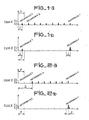
- FIG. 1a are represented for a burst the information originating from a target and received in a box x given recurrence by recurrence, in the case where this target is located at a distance D less than the range P of the radar.
- the echo of this target then appears in the first recurrence as well as in the other recurrences, 2 to r of the burst, r being the maximum number of recurrences per burst.
- the VCM filtering being first applied to the echoes of all the recurrences 1 to r, but being passing for the first, according to the invention, the level of the echo of the first recurrence is compared to a threshold S 1 and the level of the signal resulting from the VCM filtrate, applied to the echoes of the other recurrences and whose purpose is to eliminate the fixed echoes, is compared to a threshold S 2 .
- These two echoes are represented in FIG. 1b, the result of the VCM filtering carried out in real time appearing on the last recurrence of the burst.
- the two thresholds S 1 and S 2 are not identical because they must take account of the gain difference between the two signals to which they are respectively compared, difference due to the VCM device which performs integration over several recurrences.
- the two thresholds will be exceeded indicating the presence of a target seen both in recurrence 1 and in the other recurrences; so we authorize the signal to appear on the video which will deliver information distance d for the target which will be well equal to the real distance D.
- the level of the signal of the recurrence 1 is compared to the threshold S 1 and the level of the signal resulting from the filtering VCM of the other recurrences n to r is the threshold S 2 ', these two signals being represented in FIG. 2b.
- the threshold S is not exceeded while the threshold S 2 is it indicating the presence of a target at a distance greater than the range P; the signal is then prevented from appearing on the video, as this would indicate incorrect distance information.
- the corresponding echo is located from the recurrence 2, 3 or n, this is why we speak of second, third or n th trace echo.
- the object of the invention is therefore to eliminate n th trace echoes, other than the first.
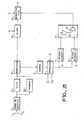
- FIG. 3 represents a block diagram of the device according to the invention.
- the conventional radar system considered to which this device is applied operates in bursts and comprises a reception chain 1 at the output of the antenna 2, followed by a device 3 for eliminating fixed echoes (VCM Visualization of moving targets) and d 'a memory circuit 30 placed in parallel.
- VCM Visualization of moving targets VCM Visualization of moving targets
- This VCM device is transparent for the first recurrence but processes the signals of the other recurrences, from the second to the last, the result of this processing appearing at the last recurrence r.
- the signals from this VCM device are then normalized with respect to noise in a normalization device 4.
- a memory circuit 5 is added to the above, delaying the information received during the first recurrence of each burst, distance box after distance box, so that they appear at the same time as those of the last and rth recurrence at the output of this memory 5 which is connected to a comparison circuit 6.
- the signals thus compared are directed to two separate logic circuits 7 and 8 determining whether the two thresholds S 1 and S 2 are exceeded, in other words if there is an echo in the recurrence 1 and / or the recurrence r of each burst. These two circuits indicate by bits 0 or 1 if the thresholds are exceeded.
- a first logic circuit 9 is arranged, composed of an inverter 10 and an AND gate 11.
- This circuit 9 delivers information in the form of bits 0 and 1 to a second logic circuit 12 whether or not delivering the ban on video representation.
- This same circuit 12 also receives the information received by the radar, via a delay circuit 13, preventing this information from arriving on the display before it is processed by the device according to the invention.
- Circuits 6, 7, 8, 12 and 13 are connected to a clock or sequencing mode to synchronize all the information.
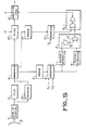
- Certain radar systems have a mass memory 14, memorizing the content of each burst and placed at the head of the VCM device, as shown in FIG. 4. According to the invention, this avoids having to put a memory circuit after the device for normalization, in order to delay the recurrence 1 compared to the recurrence r.
- the other circuits of the diagram being identical to those of FIG. 3, their references are the same.
- a threshold is added to the average value of the levels of the first trace echoes, developed during the normalization of the signals with respect to the noise, in order to achieve a "dense areas" criterion.
Claims (9)
Applications Claiming Priority (2)
| Application Number | Priority Date | Filing Date | Title |
|---|---|---|---|
| FR8116466 | 1981-08-28 | ||
| FR8116466A FR2512210A1 (fr) | 1981-08-28 | 1981-08-28 | Dispositif d'elimination des echos mobiles de ne trace et des echos parasites dans un radar |
Publications (2)
| Publication Number | Publication Date |
|---|---|
| EP0073706A1 EP0073706A1 (de) | 1983-03-09 |
| EP0073706B1 true EP0073706B1 (de) | 1986-04-09 |
Family
ID=9261747
Family Applications (1)
| Application Number | Title | Priority Date | Filing Date |
|---|---|---|---|
| EP82401517A Expired EP0073706B1 (de) | 1981-08-28 | 1982-08-10 | Radarvorrichtung bei der die vielfache Laufzeit von bewegten Echos und die Störechos ausgeschlossen ist |
Country Status (5)
| Country | Link |
|---|---|
| US (1) | US4513287A (de) |
| EP (1) | EP0073706B1 (de) |
| CA (1) | CA1203870A (de) |
| DE (1) | DE3270413D1 (de) |
| FR (1) | FR2512210A1 (de) |
Families Citing this family (6)
| Publication number | Priority date | Publication date | Assignee | Title |
|---|---|---|---|---|
| DE3222474A1 (de) * | 1982-06-15 | 1983-12-15 | Siemens AG, 1000 Berlin und 8000 München | Puls-doppler-radargeraet mit einem pulslaengen-diskriminator |
| FR2589586B1 (fr) * | 1984-01-27 | 1988-04-08 | Thomson Csf | Procede et dispositif de mesure des signaux de bruit d'un recepteur radar |
| JPS60169782A (ja) * | 1984-02-14 | 1985-09-03 | Nec Corp | 移動目標表示装置 |
| US4973968A (en) * | 1986-03-07 | 1990-11-27 | Plessey Overseas Limited | Radar system for determining first time around targets from multiple time around targets |
| US5036325A (en) * | 1989-10-05 | 1991-07-30 | Hughes Aircraft Company | Doppler determination system for MTI radars |
| FR2712094B1 (fr) * | 1993-11-02 | 1995-12-01 | Thomson Csf | Procédé de détermination du rang d'ambiguïté en distance d'échos radar. |
Family Cites Families (10)
| Publication number | Priority date | Publication date | Assignee | Title |
|---|---|---|---|---|
| US3109171A (en) * | 1961-02-06 | 1963-10-29 | George L Henry | Three-pulse canceller for coherent mti systems |
| GB1348249A (en) * | 1970-07-03 | 1974-03-13 | Plessey Co Ltd | Radar systems |
| US3828348A (en) * | 1971-10-21 | 1974-08-06 | Hughes Aircraft Co | System for minimizing multiple time around echos in a coherent-on-receive-doppler radar |
| US4168500A (en) * | 1972-03-10 | 1979-09-18 | The United States Of America As Represented By The Secretary Of The Air Force | Method and system for moving target elimination and indication using smoothing filters |
| US3995270A (en) * | 1975-06-16 | 1976-11-30 | The United States Of America As Represented By The Secretary Of The Navy | Constant false alarm rate (CFAR) circuitry for minimizing extraneous target sensitivity |
| US4025919A (en) * | 1975-11-14 | 1977-05-24 | Westinghouse Electric Corporation | Automatic target detector |
| US4095222A (en) * | 1976-03-08 | 1978-06-13 | Westinghouse Electric Corp. | Post-detection stc in a medium prf pulse doppler radar |
| US4228435A (en) * | 1979-01-23 | 1980-10-14 | The United States Of America As Represented By The Secretary Of The Air Force | Radar sensitivity time control using range gated feedback |
| US4213127A (en) * | 1979-01-31 | 1980-07-15 | The United States Of America As Represented By The Secretary Of The Air Force | Doubly adaptive CFAR apparatus |
| NL7908860A (nl) * | 1979-12-10 | 1981-07-01 | Hollandse Signaalapparaten Bv | Drempelschakeling voor radarvideosignalen. |
-
1981
- 1981-08-28 FR FR8116466A patent/FR2512210A1/fr active Granted
-
1982
- 1982-08-10 DE DE8282401517T patent/DE3270413D1/de not_active Expired
- 1982-08-10 EP EP82401517A patent/EP0073706B1/de not_active Expired
- 1982-08-25 US US06/411,567 patent/US4513287A/en not_active Expired - Fee Related
- 1982-08-27 CA CA000410354A patent/CA1203870A/en not_active Expired
Also Published As
| Publication number | Publication date |
|---|---|
| EP0073706A1 (de) | 1983-03-09 |
| CA1203870A (en) | 1986-04-29 |
| FR2512210B1 (de) | 1983-12-02 |
| US4513287A (en) | 1985-04-23 |
| FR2512210A1 (fr) | 1983-03-04 |
| DE3270413D1 (en) | 1986-05-15 |
Similar Documents
| Publication | Publication Date | Title |
|---|---|---|
| US20180356495A1 (en) | A vehicle radar system arranged for reducing interference | |
| EP0849607A1 (de) | Hindernis-Entdeckungsradar, insbesondere für Fahrzeuge | |
| EP0577479A1 (de) | Verfahren und Anordnung zur Vergrösserung der Wahrscheinlichkeit der Feststellung der Gültigkeit der Antwortkodes beim Sekundärradar | |
| EP1671152B1 (de) | Verfahren und einrichtung zum filtern von antworten in einem sekundär-radar-extraktor | |
| EP0073706B1 (de) | Radarvorrichtung bei der die vielfache Laufzeit von bewegten Echos und die Störechos ausgeschlossen ist | |
| EP0560658B1 (de) | Verfahren und Vorrichtung zur Erkennung von durch ein Sekundärradar mittels Phasenanalyse empfangenen vermischten Impulsen | |
| FR2522173A1 (fr) | Appareil et procede anticollision pour aeronefs | |
| FR2505052A1 (fr) | Procede et dispositif de reduction de la puissance des signaux de brouillage recus par les lobes secondaires d'une antenne radar | |
| US4038656A (en) | Helicopter discrimination apparatus for the murine radar | |
| EP0577478B1 (de) | Verfahren und Vorrichtung zum Filtern der Antworten in einem Sekundärradarextraktor | |
| FR2598228A1 (fr) | Radar protege contre les echos de pluie et procede de protection d'un radar contre les echos de pluie | |
| JPH035097B2 (de) | ||
| KR960704238A (ko) | 레이더 장치(Rader apparatus) | |
| EP0661555B1 (de) | Einrichtung zum Erkennen und Unterscheiden von Radarimpulsen | |
| EP0098183A1 (de) | Annäherungsradar | |
| EP0055151B1 (de) | Detektorvorrichtung für Radar-Antwortsignale und Sekundärradar mit einer derartigen Vorrichtung | |
| KR102180983B1 (ko) | 다중 표적 탐지 방법 | |
| FR2458820A1 (fr) | Dispositif d'acquisition distance dans un systeme radar | |
| US3886551A (en) | Video slope rate detector | |
| JP2558714B2 (ja) | 光学式車両検出装置 | |
| CA1194115A (en) | Electromagnetic signal receiver and processor for providing frequency data of received signals | |
| CA2266704A1 (en) | System and method for discriminating between direct and reflected electromagnetic energy | |
| EP2341366B1 (de) | Vorrichtung zum Erfassen von Impulssignalen, die eine Erfassungsfunktion von einem Garbling von Impulsen umfasst | |
| JP2843640B2 (ja) | 入力信号雑音除去装置 | |
| EP0178983B1 (de) | Schaltung zur Unterdrückung von Echos langsam bewegender Ziele bei einem Dopplerradargerät |
Legal Events
| Date | Code | Title | Description |
|---|---|---|---|
| PUAI | Public reference made under article 153(3) epc to a published international application that has entered the european phase |
Free format text: ORIGINAL CODE: 0009012 |
|
| AK | Designated contracting states |
Designated state(s): CH DE GB IT LI NL |
|
| 17P | Request for examination filed |
Effective date: 19830722 |
|
| GRAA | (expected) grant |
Free format text: ORIGINAL CODE: 0009210 |
|
| AK | Designated contracting states |
Kind code of ref document: B1 Designated state(s): CH DE GB IT LI NL |
|
| ITF | It: translation for a ep patent filed |
Owner name: JACOBACCI & PERANI S.P.A. |
|
| REF | Corresponds to: |
Ref document number: 3270413 Country of ref document: DE Date of ref document: 19860515 |
|
| PLBE | No opposition filed within time limit |
Free format text: ORIGINAL CODE: 0009261 |
|
| STAA | Information on the status of an ep patent application or granted ep patent |
Free format text: STATUS: NO OPPOSITION FILED WITHIN TIME LIMIT |
|
| 26N | No opposition filed | ||
| PGFP | Annual fee paid to national office [announced via postgrant information from national office to epo] |
Ref country code: NL Payment date: 19890831 Year of fee payment: 8 |
|
| PG25 | Lapsed in a contracting state [announced via postgrant information from national office to epo] |
Ref country code: NL Effective date: 19910301 |
|
| NLV4 | Nl: lapsed or anulled due to non-payment of the annual fee | ||
| PGFP | Annual fee paid to national office [announced via postgrant information from national office to epo] |
Ref country code: CH Payment date: 19910712 Year of fee payment: 10 |
|
| PG25 | Lapsed in a contracting state [announced via postgrant information from national office to epo] |
Ref country code: LI Effective date: 19920831 Ref country code: CH Effective date: 19920831 |
|
| REG | Reference to a national code |
Ref country code: CH Ref legal event code: PL Ref country code: CH Ref legal event code: AUV Free format text: LE BREVET CI-DESSUS EST TOMBE EN DECHEANCE FAUTE DE PAIEMENT, DE LA 11E ANNUITE. |
|
| ITTA | It: last paid annual fee | ||
| PGFP | Annual fee paid to national office [announced via postgrant information from national office to epo] |
Ref country code: DE Payment date: 19940713 Year of fee payment: 13 |
|
| PGFP | Annual fee paid to national office [announced via postgrant information from national office to epo] |
Ref country code: GB Payment date: 19940714 Year of fee payment: 13 |
|
| PG25 | Lapsed in a contracting state [announced via postgrant information from national office to epo] |
Ref country code: GB Effective date: 19950810 |
|
| GBPC | Gb: european patent ceased through non-payment of renewal fee |
Effective date: 19950810 |
|
| PG25 | Lapsed in a contracting state [announced via postgrant information from national office to epo] |
Ref country code: DE Effective date: 19960501 |