EP0073449B1 - Procédé de pesage de doses de matériau en vrac et dispositif pour la réalisation de ce procédé - Google Patents
Procédé de pesage de doses de matériau en vrac et dispositif pour la réalisation de ce procédé Download PDFInfo
- Publication number
- EP0073449B1 EP0073449B1 EP19820107717 EP82107717A EP0073449B1 EP 0073449 B1 EP0073449 B1 EP 0073449B1 EP 19820107717 EP19820107717 EP 19820107717 EP 82107717 A EP82107717 A EP 82107717A EP 0073449 B1 EP0073449 B1 EP 0073449B1
- Authority
- EP
- European Patent Office
- Prior art keywords
- weighing
- bulk material
- container
- filling
- bulk
- Prior art date
- Legal status (The legal status is an assumption and is not a legal conclusion. Google has not performed a legal analysis and makes no representation as to the accuracy of the status listed.)
- Expired - Lifetime
Links
Images

Classifications
-
- G—PHYSICS
- G01—MEASURING; TESTING
- G01F—MEASURING VOLUME, VOLUME FLOW, MASS FLOW OR LIQUID LEVEL; METERING BY VOLUME
- G01F23/00—Indicating or measuring liquid level or level of fluent solid material, e.g. indicating in terms of volume or indicating by means of an alarm
- G01F23/22—Indicating or measuring liquid level or level of fluent solid material, e.g. indicating in terms of volume or indicating by means of an alarm by measuring physical variables, other than linear dimensions, pressure or weight, dependent on the level to be measured, e.g. by difference of heat transfer of steam or water
- G01F23/28—Indicating or measuring liquid level or level of fluent solid material, e.g. indicating in terms of volume or indicating by means of an alarm by measuring physical variables, other than linear dimensions, pressure or weight, dependent on the level to be measured, e.g. by difference of heat transfer of steam or water by measuring the variations of parameters of electromagnetic or acoustic waves applied directly to the liquid or fluent solid material
- G01F23/296—Acoustic waves
- G01F23/2966—Acoustic waves making use of acoustical resonance or standing waves
- G01F23/2967—Acoustic waves making use of acoustical resonance or standing waves for discrete levels
-
- G—PHYSICS
- G01—MEASURING; TESTING
- G01G—WEIGHING
- G01G13/00—Weighing apparatus with automatic feed or discharge for weighing-out batches of material
- G01G13/24—Weighing mechanism control arrangements for automatic feed or discharge
- G01G13/30—Weighing mechanism control arrangements for automatic feed or discharge involving limit switches or position-sensing switches
Definitions
- the invention relates to a method for batch-wise weighing of bulk goods in a weighing container by means of an electronic continuous bulk scale, in which the respective actual weight of a bulk filling in the weighing container is weighed, then the bulk filling is drained, and this while adding up the actual weights for successive container fillings is repeated continuously.
- AT-B-312 955 (UNITED 7) it is known to continuously deliver product conveyed into a store below this store via an outlet in a suitable manner to a belt scale present there and then to transfer the product to another conveyor belt after weighing .
- the dosing scale is used to ensure a very precise weight with a correspondingly controlled dosing device, e.g. for filling 50 or 100 kg bags.
- the exact weight of a large amount of product is to be determined, for which continuous-bulk scales are used.
- the latter have recently been controlled by electronic control units in such a way that the scale has a predetermined target weight of e.g. 60, 80 or 120 kg is prescribed.
- the electronic control unit is connected to the computer in such a way that all the results of each batch up to the total weight can be added up immediately using a command on the input device.
- the value received can be passed on to the accounting department or a voucher can be produced using it.
- the actual weight weighing is used, for example, on acceptance scales for feed mills to determine the exact weight of the raw material items that are delivered by trucks. These are very different raw materials, among which the grain types form a major part.
- the bulk density of grain for example, varies between 0.5 and 0.8 kg / dm 3 .
- Bran which is produced by white mills as waste in the production of baking flour, is also passed on to feed mills and has a bulk density in the range from 0.1 to 0.3 kg / dm 3 .
- the electronics are equipped with a further selector switch, a correction switch for the bulk weight. With the latter, the operator can easily ensure that the weighing container is filled to some extent for each weighing cycle.
- the invention is based on the object of improving the weighing method mentioned at the outset and, in particular, of creating a method which largely eliminates the disadvantages of the known actual weight weighing.
- the best possible use of the entire weighing system should be made possible while increasing its operational reliability, incorrect entries by the operator also being excluded.
- this object is achieved in a method of the type mentioned at the outset in that the actual weight of the bulk material filling to be summed up for each individual weighing when a predetermined bulk material is reached. good level in the weighing container is determined after the bulk material supply has been interrupted.
- a predetermined target volume is selected as a control variable for determining the actual weight of the product batch.
- the control can be accomplished very simply if the determination of the bulk material fill level is carried out by a level probe arranged in the weighing container and the product feed is hereby preferably controlled in such a way that the weighing container is completely filled for each measurement and the weighing is then carried out. It is also particularly expedient if the filling of the weighing container is controlled taking into account the natural angle of repose of the product fed in, which ultimately leads to optimal container fillings. This can advantageously e.g. can be achieved in that the probe is arranged at some distance from the wall, thus in the upper region of the weighing container, starting from an average value for the angle of repose.
- Granular goods tend to assume a substantially horizontal level when poured into a container.
- bran has a relatively steep angle of repose.
- a further expedient development of the method according to the invention is that the weighing system is blocked during the filling phase and e.g. is only switched on with a full message from the level probe.
- the highly sensitive weighing system can be spared from sudden loads, as is the case when the pre-stored mass of bulk material "falls in", especially at the start of weighing.
- the above-mentioned measures can also set the calming point of the weighing system more quickly because the first jolts of the product are blocked by a blockage. For the last filling phase, the forces of the product still to be fed are small compared to the mass that the almost filled weighing container represents and hardly cause the container to vibrate.
- the invention further relates to a continuous bulk weigher for carrying out the method according to the invention, with a weighing container which has a bulk material feed line with a device for blocking it, an electronically controllable weighing system with means for detecting the actual weight of a container filling and with a device for adding up the recorded actual weights of successive container fillings.
- the generic continuous bulk weigher could be improved in a surprisingly simple manner by arranging a level probe in the weighing container through which the device for shutting off the bulk material feed line can be controlled and the means for detecting the actual weight of the container filling can be triggered.
- each element would establish an exact level and a tax from it Derive signal can be suitable for the control of the container filling according to the invention.
- a tuning fork probe is preferably used, since it can generate a clear switching signal in a sufficiently narrow area, is not very sensitive to interference and also has a certain self-cleaning effect.
- the tuning fork probe is hooked into the bulk container from above, whereby it can be attached to the bulk container or to the fixed box structure around the bulk container. The optimal placement can be found empirically easily and quickly if the type of goods to be weighed is essentially known.
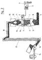
- a weighing container 1 is connected via a weighing device 2 to an input or control device 3, which can be directly connected to a printer 4.
- the weighing container 1 has a large bottom flap 5 which can be opened and closed via a remote-controlled pneumatic cylinder 6.
- the weighing container 1 is enclosed in a dust-proof weighing box 7, which in turn is enlarged in its lower part to form a collecting container 8, into which the entire contents of the weighing container 1 can be drained.
- a screw conveyor 9 guides the product from the collecting container 8 e.g. in a silo system, not shown.
- the weighing container 1 is filled with product by a feed container 10 and a feed slide 11, the feed slide 11 also being remotely controllable by a pneumatic cylinder 12.
- a tuning fork probe 13 is attached to the balance box 7 and extends with its fork 14 into the upper area of the weighing container 1.
- the bulk material for example wheat
- a truck 15 lifted over a bucket elevator 17 and transferred to a horizontal conveyor 18 which pours the wheat directly into the feed container 10.
- Fig. 1 the control of the feed device or the filling of the weighing container 1 and the weighing is shown on a larger scale:
- the bottom flap 5 is closed by the control device 3 via a control line 20 and the pneumatic cylinder 6, but the feed slide 11 is opened via a control line 21 and the pneumatic cylinder 12.
- the product can now be fed into the weighing container 1 until the product level is determined by the tuning fork 14.
- a control signal is emitted via a control line 22 for the immediate closing of the feed slide 11.
- the closing function does not have to be carried out with the accuracy of an actual dosing, since the aim of level control is to control the range.
- an actual pouring cone will form in the weighing container roughly according to lines 23, 23 '(e.g.
- tuning fork 14 By placing the tuning fork 14 at a suitable distance "A" from the side wall of the weighing container 1 and with a suitable immersion depth "H" from the upper edge of the weighing container, an optimal filling for the overall system can be specified.
- the closing signal of the tuning fork probe 13 to the feed slide 11 is now also used in the control unit 3 for triggering or the execution of the actual weighing process.
- a very precise weighing is carried out via the weighing device 2.
- the exact weight is stored in the control unit 3 and the opening of the bottom flap 5 is triggered via the control line 20.
- the bottom flap 5 can then be closed again after a corresponding time delay, so that the whole cycle can start again.
- control unit 3 adds the batch weight to the sum of the previous batch weights.
- the control unit 3 can also be designed such that a residual item weighing is carried out in response to a corresponding control command indicating the end of the item to be weighed, which is possible by bridging the tuning fork probe 13 over a time delay.
- the invention can always be used when an actual weight weighing is to be carried out by means of an electronic continuous bulk weigher. Because when using a mechanical weighing scale, neither the described actual weight weighing, nor a corresponding storage and addition is possible. In the case of mechanical scales, a precisely specified weight is weighed in automatic operation and only the number of fillings is counted.
Claims (11)
Applications Claiming Priority (2)
| Application Number | Priority Date | Filing Date | Title |
|---|---|---|---|
| CH549181 | 1981-08-26 | ||
| CH5491/81 | 1981-08-26 |
Publications (3)
| Publication Number | Publication Date |
|---|---|
| EP0073449A2 EP0073449A2 (fr) | 1983-03-09 |
| EP0073449A3 EP0073449A3 (en) | 1984-11-14 |
| EP0073449B1 true EP0073449B1 (fr) | 1990-04-25 |
Family
ID=4294475
Family Applications (1)
| Application Number | Title | Priority Date | Filing Date |
|---|---|---|---|
| EP19820107717 Expired - Lifetime EP0073449B1 (fr) | 1981-08-26 | 1982-08-23 | Procédé de pesage de doses de matériau en vrac et dispositif pour la réalisation de ce procédé |
Country Status (2)
| Country | Link |
|---|---|
| EP (1) | EP0073449B1 (fr) |
| DE (1) | DE3280159D1 (fr) |
Families Citing this family (1)
| Publication number | Priority date | Publication date | Assignee | Title |
|---|---|---|---|---|
| DE19715174B4 (de) | 1997-04-11 | 2006-11-09 | Bhs Corrugated Maschinen- Und Anlagenbau Gmbh | Einrichtung zur Herstellung einer Verbundschichtbahn |
Family Cites Families (5)
| Publication number | Priority date | Publication date | Assignee | Title |
|---|---|---|---|---|
| US3085168A (en) * | 1960-04-25 | 1963-04-09 | Gen Electric | Tuning fork |
| AT276270B (de) * | 1965-06-03 | 1969-11-25 | Vogelbusch Gmbh | Vorrichtung zur dosierten Zugabe von pulverartigen Stoffen oder Stoffgemischen, insbesondere Mehl, und von Flüssigkeit bei der Bereitung von Teigen oder Vorteigen |
| DE1773815C3 (de) * | 1968-07-10 | 1984-05-30 | Endress U. Hauser Gmbh U. Co, 7867 Maulburg | Vorrichtung zur Feststellung des Erreichens eines vorbestimmten Füllstands in einem Behälter |
| AT312955B (de) * | 1972-02-23 | 1974-01-25 | Voest Ag | Vorrichtung zur Regelung der Füllstandsmenge in einem über eine mit konstanter Geschwindigkeit angetriebenen Transportstrecke kontinuierlich befüllbaren Speicher mit fortlaufender Gutentnahme, insbesondere in einem Mischgutspeicher für Bandsinteranlagen |
| DE2612637A1 (de) * | 1976-03-25 | 1977-09-29 | Klaus Kaiser | Elektronische summierschaltung fuer waagen |
-
1982
- 1982-08-23 EP EP19820107717 patent/EP0073449B1/fr not_active Expired - Lifetime
- 1982-08-23 DE DE8282107717T patent/DE3280159D1/de not_active Expired - Fee Related
Also Published As
| Publication number | Publication date |
|---|---|
| DE3280159D1 (de) | 1990-05-31 |
| EP0073449A2 (fr) | 1983-03-09 |
| EP0073449A3 (en) | 1984-11-14 |
Similar Documents
| Publication | Publication Date | Title |
|---|---|---|
| EP0620422A1 (fr) | Procédé et dispositif pour le dosage gravimétrique et mélange d'au moins deux composants | |
| DE60110927T2 (de) | System zur zuführung von materialteilen zu einer spritzgiessmaschine | |
| DE102007050268B4 (de) | Vorrichtung zum dosierten Mischen von schüttbaren Materialkomponenten sowie Kunststoffverarbeitungsmaschine | |
| DE4447051C2 (de) | Verfahren zur portionsweisen Abgabe von Schüttgut | |
| DE3301958C2 (fr) | ||
| DE19541167C2 (de) | Vorrichtung und Verfahren zur Kalibrierung der Messung eines Gutstromes | |
| EP0140213B1 (fr) | Procédé et dispositif pour mesurer le débit de matériaux susceptibles de couler | |
| DE3134403T1 (de) | Weighing apparatus | |
| EP2232207A1 (fr) | Transporteur-doseur | |
| DE3714550C2 (fr) | ||
| DE19736979C1 (de) | Verfahren zum Zuführen von Kunststoffgranulat in die Einlauföffnung eines Kunststoffextruders | |
| DE102006061818B4 (de) | Austragsvorrichtung für pulver- oder granulatförmige Feststoffe von Dünger- bzw. Tierfutter-Dosier-Mischanlagen sowie Verfahren zum Betreiben einer solchen Vorrichtung | |
| DE19939042A1 (de) | Verfahren zur Bereitstellung eines zu dosierenden Materialgemischs und Ermittlung des Durchsatzes, und Anlage zur Durchführung des Verfahrens | |
| DE3708078A1 (de) | Verfahren und vorrichtung zum selbsttaetigen gravimetrischen abfuellen von schuettgut und/oder fluessigkeit | |
| EP0073449B1 (fr) | Procédé de pesage de doses de matériau en vrac et dispositif pour la réalisation de ce procédé | |
| DE2060490A1 (de) | Vorrichtung zum Abwaegen jeweils gleicher Mengen von stueckigen Guetern | |
| DE4033582A1 (de) | Vorrichtung zum portionsweise dosieren von schuettfaehigen waren | |
| DE2658252C2 (fr) | ||
| EP0519193B1 (fr) | Balance de dosage | |
| DE3100577C2 (de) | Automatische Dosierüberwachungseinrichtung für eine elektromechanische Waage | |
| DE3502861A1 (de) | Verfahren und vorrichtung zur betondosierung bei der herstellung von beton-fertigteilen | |
| DE3427799A1 (de) | Materialflusswaage | |
| DE19723218A1 (de) | Verfahren und Vorrichtung zum Abwägen eines schüttfähigen Gutes | |
| WO2000032473A1 (fr) | Procede et dispositif pour remplir des futs | |
| CH667530A5 (de) | Verfahren zum betreiben von dosiervorrichtungen. |
Legal Events
| Date | Code | Title | Description |
|---|---|---|---|
| PUAI | Public reference made under article 153(3) epc to a published international application that has entered the european phase |
Free format text: ORIGINAL CODE: 0009012 |
|
| AK | Designated contracting states |
Designated state(s): CH DE FR GB IT LI |
|
| PUAL | Search report despatched |
Free format text: ORIGINAL CODE: 0009013 |
|
| AK | Designated contracting states |
Designated state(s): CH DE FR GB IT LI |
|
| 17P | Request for examination filed |
Effective date: 19841206 |
|
| 17Q | First examination report despatched |
Effective date: 19860220 |
|
| ITF | It: translation for a ep patent filed |
Owner name: DE DOMINICIS & MAYER S.R.L. |
|
| GRAA | (expected) grant |
Free format text: ORIGINAL CODE: 0009210 |
|
| AK | Designated contracting states |
Kind code of ref document: B1 Designated state(s): CH DE FR GB IT LI |
|
| REF | Corresponds to: |
Ref document number: 3280159 Country of ref document: DE Date of ref document: 19900531 |
|
| GBT | Gb: translation of ep patent filed (gb section 77(6)(a)/1977) | ||
| ET | Fr: translation filed | ||
| RAP2 | Party data changed (patent owner data changed or rights of a patent transferred) |
Owner name: BUEHLER AG |
|
| REG | Reference to a national code |
Ref country code: CH Ref legal event code: PFA Free format text: BUEHLER AG |
|
| REG | Reference to a national code |
Ref country code: FR Ref legal event code: CD |
|
| PLBE | No opposition filed within time limit |
Free format text: ORIGINAL CODE: 0009261 |
|
| STAA | Information on the status of an ep patent application or granted ep patent |
Free format text: STATUS: NO OPPOSITION FILED WITHIN TIME LIMIT |
|
| 26N | No opposition filed | ||
| PGFP | Annual fee paid to national office [announced via postgrant information from national office to epo] |
Ref country code: DE Payment date: 19910802 Year of fee payment: 10 |
|
| PGFP | Annual fee paid to national office [announced via postgrant information from national office to epo] |
Ref country code: GB Payment date: 19910805 Year of fee payment: 10 |
|
| PGFP | Annual fee paid to national office [announced via postgrant information from national office to epo] |
Ref country code: FR Payment date: 19910822 Year of fee payment: 10 |
|
| ITTA | It: last paid annual fee | ||
| PGFP | Annual fee paid to national office [announced via postgrant information from national office to epo] |
Ref country code: CH Payment date: 19911010 Year of fee payment: 10 |
|
| PG25 | Lapsed in a contracting state [announced via postgrant information from national office to epo] |
Ref country code: GB Effective date: 19920823 |
|
| PG25 | Lapsed in a contracting state [announced via postgrant information from national office to epo] |
Ref country code: LI Effective date: 19920831 Ref country code: CH Effective date: 19920831 |
|
| GBPC | Gb: european patent ceased through non-payment of renewal fee |
Effective date: 19920823 |
|
| PG25 | Lapsed in a contracting state [announced via postgrant information from national office to epo] |
Ref country code: FR Effective date: 19930430 |
|
| REG | Reference to a national code |
Ref country code: CH Ref legal event code: PL |
|
| PG25 | Lapsed in a contracting state [announced via postgrant information from national office to epo] |
Ref country code: DE Effective date: 19930501 |
|
| REG | Reference to a national code |
Ref country code: FR Ref legal event code: ST |