EP0073396B1 - Homogenisation von Wasser und Toprückstand - Google Patents
Homogenisation von Wasser und Toprückstand Download PDFInfo
- Publication number
- EP0073396B1 EP0073396B1 EP82107432A EP82107432A EP0073396B1 EP 0073396 B1 EP0073396 B1 EP 0073396B1 EP 82107432 A EP82107432 A EP 82107432A EP 82107432 A EP82107432 A EP 82107432A EP 0073396 B1 EP0073396 B1 EP 0073396B1
- Authority
- EP
- European Patent Office
- Prior art keywords
- catalyst
- water
- feed
- carbo
- oil
- Prior art date
- Legal status (The legal status is an assumption and is not a legal conclusion. Google has not performed a legal analysis and makes no representation as to the accuracy of the status listed.)
- Expired
Links
Images
Classifications
-
- C—CHEMISTRY; METALLURGY
- C10—PETROLEUM, GAS OR COKE INDUSTRIES; TECHNICAL GASES CONTAINING CARBON MONOXIDE; FUELS; LUBRICANTS; PEAT
- C10G—CRACKING HYDROCARBON OILS; PRODUCTION OF LIQUID HYDROCARBON MIXTURES, e.g. BY DESTRUCTIVE HYDROGENATION, OLIGOMERISATION, POLYMERISATION; RECOVERY OF HYDROCARBON OILS FROM OIL-SHALE, OIL-SAND, OR GASES; REFINING MIXTURES MAINLY CONSISTING OF HYDROCARBONS; REFORMING OF NAPHTHA; MINERAL WAXES
- C10G11/00—Catalytic cracking, in the absence of hydrogen, of hydrocarbon oils
- C10G11/14—Catalytic cracking, in the absence of hydrogen, of hydrocarbon oils with preheated moving solid catalysts
- C10G11/18—Catalytic cracking, in the absence of hydrogen, of hydrocarbon oils with preheated moving solid catalysts according to the "fluidised-bed" technique
-
- C—CHEMISTRY; METALLURGY
- C10—PETROLEUM, GAS OR COKE INDUSTRIES; TECHNICAL GASES CONTAINING CARBON MONOXIDE; FUELS; LUBRICANTS; PEAT
- C10L—FUELS NOT OTHERWISE PROVIDED FOR; NATURAL GAS; SYNTHETIC NATURAL GAS OBTAINED BY PROCESSES NOT COVERED BY SUBCLASSES C10G OR C10K; LIQUIFIED PETROLEUM GAS; USE OF ADDITIVES TO FUELS OR FIRES; FIRE-LIGHTERS
- C10L1/00—Liquid carbonaceous fuels
- C10L1/32—Liquid carbonaceous fuels consisting of coal-oil suspensions or aqueous emulsions or oil emulsions
- C10L1/328—Oil emulsions containing water or any other hydrophilic phase
Definitions
- This invention relates to processes for converting carbo-metallic oils into lighter fractions and especially to processes for converting heavy hydrocarbons containing high concentrations of coke precursors and heavy metals into gasoline and other liquid hydrocarbon fuels.
- the invention is related to the intimate mixing or dispersion of water and the carbo-metallic oil to improve feed atomization, catalyst-feed and catalyst-water contact.
- the gas oil feedstocks contain low, if any, concentrations of coke precursors such as asphaltenes, naphthenes and porphyrins to provide a Conradson carbon (below 0.5 wt.%) and contaminant metals (Ni-V-Cu-Na), below 0.2 ppm by weight.
- concentrations of coke precursors such as asphaltenes, naphthenes and porphyrins to provide a Conradson carbon (below 0.5 wt.%) and contaminant metals (Ni-V-Cu-Na), below 0.2 ppm by weight.
- the availability of select crudes that contain a high percentage of clean gas oils has diminished and have been replaced by crude oils containing higher percentages of 566°C (1050+) material containing high concentrations of Conradson carbon producing materials and contaminant metals.
- a reduced crude contains all of the Conradson carbon and contaminant metal values as opposed to a VGO which only contains traces.
- Petroleum refiners have been investigating means for processing reduced crudes, such as visbreaking, solvent deasphalting, hydrotreating, hydrocracking, coking, Houdresid fixed bed cracking, H-oil, and fluid catalytic cracking.
- a more successful solution to the processing of reduced crude to transportation and heating fuels is Ashland Oil's Reduced Crude Process described in US-A-4,341,624; US-A-4,347,122; US-A-4,299,687; US-A-4,354,923 and US-A-4,332,673 which are herein incorporated by reference thereto.
- a reduced crude is contacted with a hot regenerated catalyst in a short contact time riser cracking zone, the catalyst and products separated instantaneously by means of a vented riser to take advantage of the difference between the momentum of gases and catalyst particles.
- the catalyst is stripped, sent to a regenerator zone and the regenerated catalyst is recycled back to the bottom of the riser to repeat the cycle. Due to the high Conradson carbon values of the feed, coke deposition on the catalyst is high and can be as high as 12 wt.% based on feed.
- This high coke level can lead to excessive temperatures in the regenerator, at times in excess of 760°C (1400°F) to as high as 816°C (1500°F), which can lead to rapid deactivation of the catalyst through hydrothermal degradation of the active cracking component of the FCC catalyst (crystalline aluminosilicate zeolites) and unit metallurgical failure.
- This homogenized mixture of carbo-metallic oil and water will yield better feed dispersion, contact with the catalyst and more uniform catalyst cooling.
- a homogenized mixture for example, of a carbo-metallic containing high boiling oil and water will permit better feed dispersion and intimate contact more rapidly with the fluid catalyst particles and thus more uniform catalyst utilization to provide the required endothermic heat of cracking to desired product selectivity in the absence of undesired cracking excursions because of poor mixing.
- the uniformity with which the catalyst heat is rapidly dispersed to the reduced crude within a contact time frame less than 2 seconds contributes substantially to product selectivity obtained.
- a process for converting carbo-metallic containing oils to lighter products comprising a process for converting carbo-metallic oil feeds to lighter products comprising:
- Steam may be added also to facilitate dispersion contact between catalyst and hydrocarbon feed.
- the step of distributing the water as very fine droplets uniformly throughout the hydrocarbon feed may be accomplished by many different techniques such as by atomizing nozzles or by more severe homogenizing equipment which will increase the interfacial contact between the water and the feed and ultimately with catalyst particles so as to enhance some of the advantages achieved by adding water. For example, it appears to permit increasing the amount of high boiling constituents in the feed passed to catalytic cracking.
- the water and carbo-metallic high boiling hydrocarbon feed are added together and a mixture thereof is subjected to shear forces sufficiently high to homogenize the mixture.
- the feed is preheated to reduce its viscosity to a temperature of at least about 149°C (300°F), and more usually, to a temperature in the range of 177°C to 232°C about 350°F to about 450°F.
- the water feed mixture is homogenized under a pressure at least high enough to maintain water in the liquid phase.
- the amount of water to be used depends upon factors discussed in more detail below, and the ratio of water to feed by weight may suitably range from about 0.04 to about 0.25, and is preferably in the range of about 0.5 to about 0.15.
- the homogenization may be carried out in a pressure vessel or in a conduit leading to the reactor.
- High speed propellors, high speed aperture discs, or other high shear agitating means may be used to homogenize the oil-water mixture.
- Emulsifying agents may optionally be used to assist with dispersion or in the homogenization. Examples of typically useful emulsifying agents are anionic surfactants, petroleum sulfonates, guanidine salts and aliphatic alcohols which may be added in amounts ranging from about 0.01 to 10% by weight of the feed. Emulsification or homogenization of oil and water can also be obtained through use of ultra-sonic devices.
- the homogenization may result in either the water or the oil as the continuous phase although in view of the larger volume of oil, the homogenized mixture will typically be a water in oil mixture, i.e., the oil will be the continuous phase.
- the average size of the droplets, such as droplets of water in the oil continuous phase of the homogenized mixture may range from less than 10 microns to over 1,000 microns and the average size is preferably in the range of about 10 to about 500 microns.
- the homogenized mixture of feed and water is introduced into the reactor either as a continuous liquid stream or as fine droplets from a spray nozzle and in a preferred method the homogenized mixture is admixed with hot catalyst particles as relatively fine droplets having an average size less than about 350 microns and more preferably having an average size less than about 100 microns.
- droplets brought into contact with hot catalyst particles contain both water and oil, and the rapid heating of water within the droplets to fine steam breaks the oil into even smaller droplets thus obviating the need for providing special high cost atomizing apparatus to produce carbo-metallic oil droplets significantly smaller than about 100 microns and of about 20 microns size or less.
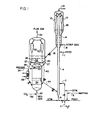
- Figure 1 is a schematic diagram of an apparatus arrangement for carrying out the process of the invention.
- the present invention is directed to an improvement in the approach to the conversion of carbo-metallic oil feeds, such as reduced crude or the like, to lighter and heavier products such as gasoline and fuel oils.
- the carbo-metallic oil feed comprises an oil which boils above about 343°C (650°F) and includes vacuum tower bottoms.
- Such oils are characterized by a heavy metal content of at least about 4 ppm, and preferably at least about 5.5 ppm of Nickel Equivalents by weight and by a carbon residue on pyrolysis of at least about 4% and more usually at least about 6% by weight.
- the carbo-metallic feed in the form of a pumpable liquid, is mixed or dispersed with water to provide a highly agitated mixture thereof such as a homogenized mixture which is brought into dispersed phase contact with hot conversion catalyst normally in the presence of added steam and in a weight ratio of catalyst to oil feed in the range of about 3 to about 19 and preferably more than about 6 to 1.
- the hydrocarbon feed in said mixture undergoes conversion which includes cracking while the mixture of feed, steam and catalyst flow as a high temperature suspension through a progressive flow type reactor.
- the reactor is an elongated reaction chamber in which the feed material, resultant products of cracking, steam and catalysts are maintained in contact with one another while flowing as a dilute phase for a predetermined reactor residence time in the range of about 0.5 to about 5 seconds.
- the feed, catalyst, and dispersion diluent materials may be introduced into the reactor at one or more spaced points along the length of the reactor such as a riser reactor.
- the cracking reaction conducted at a temperature to provide a riser outlet temperature of 482°C to 649°C (about 900° to about 1200°F) at a hydrocarbon residence time less than 5 seconds at a total pressure of 69 to 345 kPa (about 10 to about 50 psia (pounds per square inch absolute) under conditions sufficiently severe to provide a conversion per pass in the range of about 50% or more and to lay down coke on the catalyst in the form of hydrocarbonaceous deposits in an amount in the range of about 0.3 to about 3% by weight of catalyst and preferably at least about 0.5%.
- the overall rate of coke production, based on weight of fresh feed is in the range of about 4 to about 14% by weight.
- the catalyst is separated from the products, is stripped to remove vaporous components and is then regenerated with oxygen-containing combustion-supporting gas under conditions of time, temperature and atmosphere sufficient to reduce residual carbon on the regenerated catalyst to below 0.1% and preferably below 0.05% or less by weight.
- the regenerated catalyst is recycled at a desired temperature to the riser to repeat the cycle.
- the invention is applicable to carbo-metallic oils, whether of petroleum origin or not.
- carbo-metallic oils whether of petroleum origin or not.
- the invention may be applied to the processing of such widely diverse materials as heavy bottoms from crude oil, heavy bitumen crude oil, those crude oils known as "heavy crude” which approximate the properties of reduced crude, shale oil, tar sand extract, products from coal liquification and solvated coal, atmospheric and vacuum reduced crude, aromatic extract from lube oil refining, tar bottoms, heavy cycle oil, slop oil, and refinery waste streams comprising mixture of the foregoing.
- Such mixtures can for instance be prepared by mixing available hydrocarbon fractions, including oils, tars, pitches and the like.
- powdered coal may be suspended in the carbo-metallic oil.
- An advantage of the invention process is that feedstocks comprising carbo-metallic oils that have had no prior demetalation treatment can be employed.
- the concepts of the invention are applicable to feedstocks with or without prehydrogenation treatment.
- a preferred application of the process is directed to processing reduced crude, i.e., that fraction or portion of crude oil boiling above 343°C (650°F), alone or in admixture with atmospheric virgin gas oils.
- a carbo-metallic oil feedstock with or without atmospheric gas oils and comprising at least about 70%, of materials which boil above about 343°C (650°F) and comprising the residence material normally separated by vacuum distillation is charged as the feed. All boiling temperatures herein identified are based on standard atmospheric pressure conditions.
- Carbo-metallic oil partly or wholly composed of material which boils above about 345°C (650°F) is referred to herein as 343°C+ (650°F+) material.
- the carbo-metallic oils processed according to the invention contain material which do not boil under any conditions; that is, certain asphalts and asphaltenes, porphyrins and some multi-ring high molecular weight compounds crack thermally during distillation, apparently without boiling. These non-boilable materials for the most part are concentrated in portions of the feed which do not boil below 552°C to 566°C (about 1025°F or 1050°F).
- the contemplated high boiling feeds have a carbon residue on pyrolysis of at least about 2 or greater.
- the Conradson carbon content may be in the range of about 2 to about 12 and most frequently at least about 4. A particularly common range is about 4 to about 8.
- Those feeds providing a Conradon carbon deposition on the cracking catalyst greater than about 6 require special consideration for controlling excess heat in the combustion thereof in a regenerator.
- the high boiling hydrocarbon feeds generally have a composition characterized by an atomic hydrogen to carbon ratio in the range of about 1.2 to about 1.9, and more usually in the range of about 1.3 to about 1.8.
- the carbo-metallic feeds contemplated and containing high boiling oil at least the 543°C+ (650°F+) material will contain at least about 4 parts per million of Nickel Equivalents, as defined by the formula (metals as ppm by weight).
- the carbo-metallic containing oil feeds process as herein provided also usually contain significant quantities of heavy, high boiling compounds containing nitrogen, a substantial portion of which may be basic nitrogen.
- nitrogen a substantial portion of which may be basic nitrogen.
- the total nitrogen content of the carbo-metallic oils may be at least about 0.05% by weight. Since cracking catalysts owe their cracking activity to acid sites on the catalyst surface or in its pores, basic nitrogen-containing compounds may temporarily neutralize some of these sites, thereby poisoning the catalyst. However, the catalyst is not permanently damaged since the nitrogen is removed during combustion of carbonaceous deposits during catalyst regeneration, as a result of which, the acidity of the active sites is restored.
- the carbo-metallic oils may also include significant quantities of pentane insolubles, for example, at least about 0.5% by weight, and more typically 2% or more or even about 4% or more. These may include for instance asphaltenes and other materials.
- the carbo-metallic oil containing feedstock thus constitutes in one embodiment at least about 70% by volume of material which boils above about 343°C (650°F), and at least about 10% of the material which boils above and outside the range of 343°C (650°F) up to 552°C (about 1025°F).
- the average composition of this 343°C+ (650°F+) material may be further characterized by: (a) an atomic hydrogen to carbon ratio in the range of about 1.3 to about 1.8; (b) a Conradson carbon value of at least about 2; (c) at least about four parts per million of Nickel Equivalents, as defined above, of which at least about two parts per million is nickel (as metal, by weight); and (d) at least one of the following: (i) at least about 0.3% by weight of sulfur, (ii) at least about 0.05% by weight of nitrogen, and (iii) at least about 0.5% by weight of pentane insolubles.
- the preferred feed will include all of (i), (ii), and (iii), and other components found in oils of petroleum and non-petroleum origin may also be present in varying quantities providing they do not prevent desired operation of the process.
- the weight ratio of catalyst to fresh feed used in the process is in the range of about 3 to about 18. Preferred ratios are from about 4 to about 12, a ratio of about 10 presently being considered most desirable for some feeds.
- the process of the invention is practiced with catalyst bearing accumulations of heavy metal(s) in the form of elemental metal(s), oxide(s), sulfide(s) or other compounds which heretofore would have been considered quite intolerable in conventional FCC-VGO operations.
- catalyst bearing heavy metals accumulations at least of about 3,000 or more ppm Nickel Equivalents, on the average, is contemplated.
- the concentration of Nickel Equivalents of metals on the catalyst can also be as high as about 50,000 ppm or higher. More specifically, the metals accumulation may be in the range of about 6,000 to 30,000 ppm, and preferably at least 10,000 ppm. within these ranges one can tend to reduce the rate of catalyst replacement required.
- a preferred class of catalysts includes those which have pore structures into which high molecular weight component of the feed material may enter for adsorption and/or contact with active catalytic sites within or adjacent the pores.
- Various catalysts compositions are available particularly comprising crystalline zeolites dispersed in a matrix material considered neutral or comprising catalytic activity.
- the matrix material may be silica alumina, a mixture of silica-alumina in admixture with a clay binder material.
- a particularly desirable zeolite is catalytically activated crystalline "Y" faujasite zeolite comprising high levels of lanthanum/cerium ratio.
- the zeolite-containing catalysts may include substantially any zeolite, whether natural, semisynthetic or synthetic, in admixture with other might employ equilibrium catalyst from another unit, for example, an FCC unit which has been used in the cracking of a feed, e.g., vacuum gas oil, having a carbon residue on pyrolysis of less than 1 and containing less than about 4 ppm Nickel Equivalents of heavy metals.
- an FCC unit which has been used in the cracking of a feed, e.g., vacuum gas oil, having a carbon residue on pyrolysis of less than 1 and containing less than about 4 ppm Nickel Equivalents of heavy metals.
- a particularly preferred class of catalysts includes those which have pore structures into which molecules of feed material may enter for adsorption and/or for contact with active catalytic sites within or adjacent the pores.
- Various types of catalysts are available within the classification, including for example the layered silicates, e.g. smectites. Although the most widely available catalysts within this classification are the well-known zeolite-containing catalysts, non-zeolite catalysts are also contemplated.
- the preferred zeolite-containing catalysts may include any zeolite, whether natural, semisynthetic or synthetic, alone or in admixture with other materials which do not significantly impair the suitability of the catalyst, provided the resultant catalyst has the activity and pore structure referred to above.
- the virgin catalyst is a mixture, it may include the zeolite component associated with or dispersed in a porous refractory inorganic oxide carrier.
- the catalyst may for example contain about 1% to about 60%, more preferably about 15 to about 50%, and most typically about 20 to about 45% by weight, based on the total weight of catalyst (water free basis) of the zeolite, the balance of the catalyst being the porous refractory inorganic oxide alone or in combination with any of the known adjuvants for promoting or suppressing various desired and undesired reactions.
- the genus of leucite, lazurite, scaplite, mesolite, ptolite, nephline, matrolite, offretite and sodalite for a general explanation of the genus of leucite, lazurite, scaplite, mesolite, ptolite, nephline, matrolite, offretite and sodalite.
- Examples of the synthetic crystalline aluminosilicate zeolite which are useful as or in the catalyst for carrying out the present invention are zeolites X, Y, A, B, D, E, F, H, J, L, M, 0, Q, S, T, W, Z, Omega, ZK-411J, alpha, beta and ZSM-type.
- the crystalline aluminosilicate zeolites having a faujasite-type crystal structure are particularly preferred for use in the present invention. This includes particularly natural faujasite, Zeolite X, Zeolite Y and combinations thereof.
- a catalyst composition particularly suitable for use in the present invention are characterized by comprising matrices with feeder pores having large minimum diameters and large pore size openings in the range of 5 to 20x10- 8 metres (500 to 2000 angstroms) to facilitate diffusion of high molecular weight molecules in the matrix to the portal surface area of molecular sieve particles within the matrix.
- Such matrices preferably also have a relatively large pore volume in order to soak up unvaporized portions of the carbo-metallic oil feed. Thus significant numbers of liquid hydrocarbon molecules can diffuse to active catalytic sites both in the matrix and in sieve particles on the surface of the matrix.
- catalysts having a total pore volume greater than 0.2 cc/gm, preferably at least 0.4 cc/gm and more usually in the range of 0.5-0.8 cc/g.
- the matrix pore size may have some diameters in the range of 40 to 60x10- 8 metres (about 400 to about 6000 angstrom units) with a major portion thereof in the range of 5 to 20x10- 8 metres (500 to 2000 angstroms).
- a catalyst comprising a combination of two or more different catalytically activated crystalline zeolites having distinctly determinable different pore sizes may be employed.
- a relatively large pore size opening crystalline zeolite is represented by type X and Y crystalline faujasites and the like.
- a second type of crystalline zeolite of smaller pore size may be mixed therewith to provide pore size openings in the range of 4-13xlO- lo metres (about 4A up to about 13A) and the combination utilized for selective cracking and isomerization of normal paraffins or olefins.
- a selective n-paraffin conversion zeolite is represented by A-type zeolite, mordenite, erionite, offretite and other small pore zeolite identified in the prior art.
- the reduced crude cracking catalyst is therefore comprised of a Y type crystalline zeolite, with rare earth stabilization, with or without admixture of a smaller pore size opening zeolite to provide a catalyst composition highly selective for conversion of reduced crudes.
- a combination crystalline zeolite catalyst may comprise from about 5 to about 40 wt.% of a faujasite crystalline zeolite in combination with 5 to 40 wt.% of a smaller pore size opening zeolite.
- These zeolitic components used separately or together are preferably bound together by a matrix material comprising silica, alumina, silica-alumina, kaolin, activated clays or other known binder materials suitable for the purpose.
- Additives may be employed with the catalyst to passivate the non-selective catalytic activity of heavy metals deposited on the conversion catalyst.
- Catalysts for carrying out the present invention may also employ metal additives for controlling the adverse effects of vanadium as described in AU-D-78958/82. It is also preferred to control the valence state of vanadium accumulations on the catalyst during regeneration.
- the entire disclosure of said patent is incorporated herein by reference.
- the mixing and dispersing of oil and water mixtures which include Kady Mills.
- Dispersators, Colloid Mills are used alone or in combination with fine droplets atomizing nozzles.
- Some of these homogenizers depend on close tolerances between their milling surfaces for effecting shear, attrition and impact forces to produce dispersion.
- the Kady Mill does not depend on close tolerance between its surfaces and also avoids shear as much as possible, but utilizes impact and attrition for its effective and efficient dispersion action.
- the Kady Mill dispersion unit consists of a pressure vessel (capable of 690 kPa and 288°C (100 psia and 550°F)) and a bottom propellor to assist in bottom batch movement and a slotted motor operating within a slotted stator partially enclosed at the top and bottom by head plates.
- the rotor operating at high speeds (rotor rim speeds of 2652 metres per mm (8700 fpm), functions as a pump and draws material from above and below, and jets it at high speed through the slots in the stationary ring surrounding it.
- Dispersion is affected mainly by impact.
- the agglomerate leaves the rotor tangentially at high speed and is abruptly stopped by the stationary wall of the stator slot. Its direction is then changed and after two additional but lesser impacts, it emerges into the batch in a jet stream where a degree of internal shear assists in the dispersion or homogenization process.
- a Dispersator with a high viscosity mixing head in the appropriate vessel that can maintain pressure up to 690-2758 kPa (100-400 psig) and temperatures as high as 288°C (550°F).
- the high viscosity mixing head is known as Premier Hi-Vis and can handle materials with viscosities as high as 30 Pas (30,000 centi- poises).
- the high viscosity oil plus water is sucked in the end of the Dispersator or through the slots as the slotted cylindrical head rotates at high speed. Centrifugal force whirls the material out through the slots.
- Another method for effecting the homogenization of oil and water is through the use of a colloid mill.
- This operation can produce water droplets in oil below 1,000 microns in size.
- the material to be dispersed or emulsified is fed to a rapidly spinning rotor.
- This rotor is closely matched to a stationary stator as to distance between the rotor and stator 0.0025-0.32 cm (.001-.125 inches).
- centrifugal force As the material comes in contact with the rotor it is flung out to the edge by centrifugal force. This force pushes the material through the narrow gap between the rotor and stator. This imports high shear to the material and overcomes the surface forces tending to hold the material together.
- the material makes its way through the shear zone and is flung out into an open area.
- the speed at which a colloid mill operates is extremely important.
- the linear speed at the rotor face, where the work is done, must be high enough to develop sufficient hydraulic shear. This linear speed is a function of RPM and rotor diameter and should be at least 3600 RPM.
- the homogenization of water into a reduced crude by employment of one of the mixing devices described above can produce water droplet size near 1,000 microns.
- an emulsification agent By incorporating an emulsification agent into the oil-water mixture this water droplet size can be further reduced dramatically.
- the use of an emulsifier can reduce water droplet size to below 1,000 microns, in particular to the size range of 10-350 microns.
- Example of some typical emulsifiers and their range of concentration in the oil-water mixture include C1+Cslow molecular weight alcohols and particularly methanol and isopropanol: 0.01-2 wt.% anionic surfactant; 0.01-0.5 wt.% of a quanidine salt; 0.01-0.5 wt.% of an oxyalkylated N-containing aromatic compound such a nitrophenyl or quinolinyl sulfonyl polyalkylene hydroxide; 0.1-10 wt.% of monoethanolamine nonyl or dodecyl orthoxylene sulfonate; 0.1-10% of a petroleum sulfonate.
- An important aspect of the use of a mixing vessel with an emulsifying agent and particularly the alcohols to yield a homogenized mixture of oil and water is the distribution of fine water droplet size in the oil phase and the solubilizing effect of particularly isopropanol which will contribute to a fine oil droplet size upon introduction of the mixture into a riser reactor as by atomizing spray nozzles for contact with the hot regenerated catalyst.
- This homogenizing concept contributes substantially to improving contact between high boiling feed and catalyst whether used alone or in combination with highly efficiency spray nozzles to obtain a more highly dispersed phase contact of reduced crude with fluid catalyst particles in a cracking time frame less than 3 seconds.
- liquid water is homogenized with the carbo-metallic oil with or without emulsifying agent in a weight ratio of about 0.04 to about 0.25.
- the heat of vaporization of the water which heat is absorbed from the catalyst, from the feedstock, or from both, provides a more efficient heat sink which upon conversion to steam promotes atomization of the feed as discussed herein.
- the weight ratio of liquid water to feed is within the range of about 0.04 to about 0.2.
- the amount of additional steam may be in a weight ratio relative to feed in the range of about 0.01 to about 0.25, with the weight ratio of total H 2 0 (as steam and liquid water) to feedstock being about 0.3 or 0.4 to 0.8 grams/cc (about 25 to about 50 pounds per cubic foot).
- the gaseous products of combustion or flue gases obtained in the presence of limited or excess oxygen may include an amount of free oxygen.
- free oxygen unless removed from the by-product gases or converted to some other form by a technique other than carbon burning regeneration, will normally manifest itself as free oxygen in the flue gas from the regenerator unit.
- Fluidization is maintained by passing gases, including combustion supporting gases, through a catalyst bed undergoing regeneration at a sufficient velocity to maintain the particles in a fluidized state but at a velocity which is sufficient to prevent substantial and undesired entrainment of particles in the overhead flue gases.
- the lineal velocity of the fluidizing gases may be in the range of 0.061 to 1.22 metres/sec (about 0.2 to about 4 feet per second) and preferably 0.061 to 0.91 metres/sec (about 0.2 to about 3 feet per second).
- the average total residence time of the particles in one or more separate catalyst beds being regenerated is substantial, ranging for example, from about 5 to about 30 minutes and more usually from about 5 to about 20 minutes.
- Heat released by combustion of coke in the regenerator is absorbed in part by the regenerated catalyst and is normally retained until the regenerated catalyst is brought into contact with fresh feed or other cooling agent.
- the amount of regenerator heat which is transmitted to fresh feed by way of recycling regenerated catalyst can substantially exceed the level of heat input which is appropriate in the riser for heating, vaporizing the feed, vaporizing added water, and other materials, and for supplying the endothermic heat of reaction for cracking, as well as for making up the heat losses of the unit.
- the amount of regenerator heat transmitted to fresh feed may be controlled, or restricted as necessary, within certain desired ranges.
- the amount of heat so transmitted may for example be in the range of 278 to 667 calories/gram (about 500 to about 1200), more particularly 333 to 500 cal/gm (about 600 to about 900), and more particularly 361 to 472 calories/gm (about 650 to about 850 BTUs per pound) of fresh feed.
- the aforesaid ranges refer to the combined heat, in calories/gm (BTUs per pound) of fresh feed, which is transmitted by the catalyst to the feed and reaction products (between the contacting of feed with the catalyst and the separation of product from catalyst) for supplying the heat of reaction (e.g., for cracking and the difference in enthalpy between the products and the fresh feed.
- One or a combination of techniques may be utilized for controlling or restricting the amount of regeneration heat transmitted via catalyst to fresh feed. For example, one may inhibit a combustion of carbonaceous material on the cracking catalyst in order to reduce the temperature of combustion to form carbon dioxide and/or carbon monoxide in the regenerator. Moreover, one may remove heat from the catalyst through heat exchange means, including for example, heat exchangers (e.g., steam coils) built into the regenerator itself, whereby one may extract heat from the catalyst during regeneration. Heat exchangers can be built into catalyst transfer lines, such as for instance the catalyst return line from the regenerator to the reactor, whereby heat may be removed from the catalyst after it is regenerated. One may also inject cooling fluids into portions of the regenerator other than those occupied by the dense bed and into the dense catalyst bed. For example water and/or steam may be directly added whereby the amount of gasiform material available in the regenerator for heat absorption and removal is increased.
- heat exchangers e.g., steam coils
- Another suitable technique for controlling or restricting the heat transmitted to fresh feed via recycled regenerated catalyst involves maintaining a specified ratio between the carbon dioxide and carbon monoxide formed in the regenerator while such gases are in heat exchange contact or relationship with catalyst undergoing regeneration.
- all or a major portion by weight of the coke present on the catalyst as hydrocarbonaceous deposits immediately prior to regeneration is removed in one or more combustion zones in which the aforesaid ratio is controlled as described below. More particularly, at least about 65% by weight of the coke on the catalyst is removed in a combustion zone in which the molar ratio of CO to CO 2 is maintained at a level providing a CO rich gas.
- CO production is promoted while catalyst is being regenerated to about 0.1 % carbon or less, and preferably to about 0.05% carbon or less.
- Another particular technique for controlling or restricting the regeneration heat imparted to fresh feed via recycled catalyst involves a diversion of a portion of the heat borne by recycled catalyst to added materials introduced before the reduced crude feed into the reactor, such as water, steam, naphtha, hydrogen donor materials, flue gases, inert gases, and other gaseous or vaporizable catalyst fluidizing materials which may be introduced into the reactor before the higher boiling feed.
- the amount of oxidizing gas that enters said first zone and the concentration of oxygen or oxygen bearing gas therein is sufficient for affecting only partial removal of carbonaceous material and effecting the desired conversion of hydrogen associated therewith to form carbon oxides.
- the thus partially regenerated catalyst with or without some retained hydrogen is then removed from the first regeneration zone and conveyed to a second regeneration zone.
- a regeneration gas such as oxygen, or C0 2 is introduced into the second regeneration zone to complete the removal of carbonaceous material to a desired low carbon level.
- the regenerated catalyst is then removed from the second zone and recycled to the hydrocarbon conversion zone for contact with fresh feed.
- An example of such multi-stage regeneration process is described in U.S. Patent 2,938,739.
- Multi-stage regeneration offers the possibility of combining oxygen deficient regeneration with the control of the CO:C0 2 molar ratio.
- about 50% and more usually about 65% to about 95%, by weight of the coke on the catalyst immediately prior to regeneration may be removed in one or more stages of regeneration in which the molar ratio of CO:CO 2 is controlled in the manner described above.
- a multi-stage regeneration operation is particularly beneficial in that it provides another convenient technique for restricting regeneration heat transmitted to fresh feed via regenerated catalyst and/or reducing the potential for thermal deactivation, while simultaneously affording an opportunity to reduce the carbon level on regenerated catalyst to very low percentages (e.g., about 0.1% or less) which particularly enhances catalyst activity.
- a two-stage regeneration process may be carried out with the first stage combustion providing a bed temperature of about 1300°F to produce a CO rich flue gas and the second stage combustion providing a bed temperature of about 1350°F to also produce a CO rich flue gas with little, if any, free oxygen.
- a catalyst residence time of up to 15 or 20 minutes total in the two zones is not unusual.
- the regeneration temperature conditions may be substantially more severe in the first regeneration zone than in the second zone such as when effecting endothermic removal of carbonaceous material with C0 2 in the second zone.
- a particularly preferred embodiment of the invention is a two-stage fluidized catalyst oxygen regeneration operation at a maximum temperature of 760°C (about 1400°F) with a reduced temperature of at least -12° to -7°C (about 10 or 20°F) in a dense catalyst phase of the first stage as compared to the dense catalyst phase of the second stage.
- the catalyst can thus be regenerated to carbon levels as low as 0.01% by this technique in the absence of thermal degradation even though the carbon on catalyst prior to regeneration is about 1 wt.% or more.
- the hydrocarbon feed comprising a reduced crude, residual oil or a topped crude comprising carbon-metallic oil impurities boiling above 552°C (about 1025°F) homogenized with water and is charged to a riser reactor conversion zone through one of the feed inlet conduit means 6, 2 or 7 as desired to provide a vaporized hydrocarbon residence contact time with catalyst in the riser within the range of 0.5 seconds up to about 3 or 4 seconds but more usually within the range of 1 or 2 seconds.
- An emulsifying agent to increase the degree of reduced crude-water homogenization and reduce the water droplet size in the emulsion can be added to the water prior to introduction to the homogenizer section.
- the hydrocarbon feed so charged may be mixed with one or more of water, steam, naphtha, hydrogen and other suitable gasiform diluent material or a combination of these materials which will operate to achieve conversion of the feed desired, reduce the feed partial pressure, effect temperature control, and effect atomization-vaporization of the feed before and during contact with hot cracking catalyst charged by conduit 7 to an upper portion of the riser reactor to reduce hydrocarbon residence time, provisions, not shown, are provided for adding on or more of the materials above identified for promoting the conversion desired, effect temperature control and assure efficient atomization-vaporization of the charged high boiling feed.
- the high boiling charged oil feed comprising a reduced crude or residual oil may be as temperature recovered from, for example, an atmospheric distillation zone or a vacuum distillation zone (not shown).
- the feeds processed by this invention comprise materials having an initial boiling as low as 343°C (650) or 371°C (700°F) or a higher boiling portion of the crude such as heavy vacuum gas oil and higher boiling residue material may be charged as the feed.
- an upflowing suspension of the hydrocarbon feed, diluent material and suspend hot catalyst particles is formed at an elevated temperature sufficient to provide required endothermic heat of cracking and provide a vaporized hydrocarbon product- catalyst suspension at the riser discharge at a temperature within the range of 510°C (950°F) up to 621°C (about 1150°F), and more usually at least 538°C (about 1000°F) depending upon the severity of cracking and product slate desired.
- the riser cracking operation of this invention is accomplished with the special high activity-metals tolerant zeolite containing cracking catalyst herein defined and characterized as GRZ-1 Special at a hydrocarbon residence time in the riser preferably less than about 2 seconds and within the management parameters herein defined.
- the suspension following traverse of riser 4 is rapidly separated as by ballistic separation or other comparable means at the riser discharge 8 so that vaporous material with any entrained particle fines can be further separated in adjacent cyclone separating equipment 10 before recovery of vaporized hydrocarbons by conduit 12.
- the recovered vaporous hydrocarbons are passed to separation equipment not shown for recovery for desired product fractions comprising C 2- C S hydrocarbons, naphtha, gasoline, light and heavy fuel oil product fractions. Of these recovered product fractions, it is contemplated recycling recovered dry gas comprising hydrogen and methane, naphtha and C 2 -C S hydrocarbons.
- riser 4 is confined within a vessel means 48 which is contiguous in the lower portion with an annular stripping zone about the riser in the specific arrangement of the drawing. It is contemplated however using a cylindrical stripping zone in association with a bottom portion of catalyst collecting vessel 48 through which riser 4 does not pass.
- the catalyst separated at the riser discharge and by the cyclones is collected about riser 4 in the arrangement of Figure 1 and passed down through the annular stripping zone countercurrent to stripping gas charged by conduit 16.
- the stripping of catalyst in zone 14 is preferably accomplished at a temperature of at least 510°C (950°F) and is more desirably effective when accomplished at elevated temperatures of at least 538°C (1000°F).
- C0 2 as the stripping medium where relatively high levels of hydrocarbonaceous materials are deposited on the catalyst is to obtain reaction with and at least partial removal of hydrogen associated with the carbonaceous deposits.
- the reaction of C0 2 with hydrogen to produce methane and water is known as the methanation reaction which is an exothermic reaction accomplished at temperatures in the range of 371° to 427°C (about 700 to 800°F).
- the promotion of this reaction in the stripping section may require some cooling of catalyst separated from the riser reactor when exiting at a temperature of at least 538°C (1000°F).
- This partial removal of hydrogen is desirable prior to oxygen regeneration of the catalyst because of the high heat released by the combustion of hydrogen with oxygen.
- heat management during oxygen regeneration may be more easily controlled.
- a reduced crude cracking operation defers in kind from a normal gas oil fluid cracking operation rather than just in a difference in operating degree because of the severity of the operation, the metal loading which must be tolerated by the cracking catalyst at desired catalyst activity as well as the high level of hydrocarbonaceous material (coke plus hydrogen) deposited on the catalyst during the cracking of high boiling carbo-metallic containing reduced crudes.
- the deposited metals are associated with deposited hydrocarbonaceous material and applicants have observed that high temperature stripping in a turbulent atmosphere appears to contribute to some removal of deposited metals such as nickel since its level of accumulation does not continue to parallel that of vanadium.
- sequential regeneration of the catalysts may be accomplished with C0 2 in the stripper zone, and with oxygen containing gas in a sequence of regeneration zone or one of the regeneration zones such as the last zone may be employed for effecting a partial regeneration of residual carbon with CO 2 rich gas under endothermic regenerating conditions to remove the residual carbon thereby cooling the catalyst.
- initial removal of carbonaceous material may be accomplished with hot C0 2 rich gas and then with oxygen in a second stage.
- the sequence of regeneration is selected and controlled to remove hydrocarbonaceous deposits within the management parameters discussed above and to provide a catalyst of low residual coke less than 0.1% by weight at a temperature below 871°C (1600°F) and preferably below 816°C (1500°F). More particularly, regeneration temperatures are maintained in the presence of steam below 760°C (1400°F) which will substantially limit or eliminate hydrothermal degradation of the catalyst and yet provide required endothermic temperature input to the reduced crude cracking operation in riser 4.
- the stripped catalyst is passed on conduit 18 to a first stage of catalyst regeneration in catalyst bed 22 maintained in the upper portion of vessel 20.
- Regeneration gas is provided to the lower portion of bed 22 by conduit 24 to plenum chamber 26 and thence through distributor arm means 27.
- gaseous products of regeneration effected in a lower zone comprising bed 34 pass through passage ways 29 in baffle 28. Since the regeneration flue gases of the regeneration operation herein contemplated are compatible with one another, the regeneration system of Figure 1 is a most versatile system for accomplishing desired carbon removal to a desired low level and is implemented to some considerable extent when removing hydrogen with C0 2 in the stripping zone.
- the CO rich flue gas may be passed to a separate combustion zone to burn combustible material such as CO and produce a high temperature C0 2 rich gas in the range of 538°C to 816°C (1000°F to about 1500°F) for use as herein provided.
- the partially regenerated catalyst obtained as above provided is passed by one or both stand- pipes 36 and 40 to bed 34 in the lower portion of the regeneration vessel.
- a heat exchange means 38 is provided in conduit 36 should there be a need to heat or cool catalyst passed through conduit 36.
- heat exchanger 38 may be employed to effect some cooling of catalyst passed through standpipe 36 and before discharge in the lower catalyst bed.
- catalyst bed 34 a burning of residual carbon and any hydrogen if present, depending on that accomplished in the stripper and in bed 22 is further accomplished by adding an oxygen containing gas such as air by conduit 42.
- some C0 2 may be added to reduce the concentration of oxygen in the gas employed in the second regeneration zone comprising bed 34.
- Regeneration of the catalyst accomplished in bed 34 is a temperature restricted clean-up operation designed and operated to remove residual hydrogen if present and particularly to reduce residual carbon the catalyst to a low value below about 0.5 wt.% and preferably below 0.1 wt.%.
- this clean-up regeneration operation it is desirable to restrict the regeneration temperature not to exceed 816°C (about 1500°F) and preferably the regeneration temperature is restricted not to exceed 760° to 788°C (about 1400°F or 1450°F). This temperature restriction will remain the same whether oxygen or C0 2 regeneration of the catalyst is pursued in this cleanup operation.
- the catalyst regenerated according to one of the sequences above provided is withdrawn by conduit 44 for passage at an elevated temperature in a lower portion of riser 4. It is contemplated stripping the regenerated catalyst in a stripping zone not shown within or external bed 34 with C0 2 or other gas suitable for the purpose to remove combustion supporting gases from the withdrawn catalyst. It is desirable when the catalyst is regenerated with C0 2 or oxygen in bed 34 to strip the catalyst to remove any entrained (CO) carbon monoxide before charging the catalyst to the riser.
- CO entrained
- regenerators of the type shown in Figures 1 and 2 which have countercurrent flow and are well- suited for producing combustion product gases having a low ratio of C0 2 to CO, which helps lower regeneration temperatures in the presence of high carbon levels.
- a carbo-metallic feed at a temperature of 177°C (about 350°F) is introduced into a homogenization vessel together with liquid water at a water-to- feed ratio by weight of 0.25.
- the pressure in the vessel is 930 kPa (135 pounds per square inch absolute).
- the homogenizer is a Kady Mill employing the mixing apparatus as described in the invention.
- the water contains 0.1 wt.% of a petroleum sulfonate as an emulsifying agent.
- the resulting homogeneous mixture is atomized into droplets having an average droplet size of about 100 microns and is introduced into a bottom portion of a riser reactor zone at a rate of about 908 kg per hour (2000 pounds per hour) of feed where it is mixed with a zeolite-containing cracking catalyst at a temperature of 691°C (about 1275°F).
- the ratio by weight of catalyst to oil is about 11:1.
- the carbo-metallic feed has a heavy metal content of about 5 parts per million Nickel Equivalents, a Conradson carbon content of about 7 percent, and contains about 500 ppm nitrogen in the form of basic nitrogen compounds. Substantially all of the feed boils above 343°C (650°F) and about 20% of the feed does not boil below 552°C (about 1025°F).
- the catalyst is an alumino silicate zeolite dispersed in a silica alumina matrix, the zeolite being present in an amount of about 15% by weight.
- the matrix has substantial feeder pores with a diameter in excess of 4x10- 8 metres (about 400 angstroms).
- the catalyst particles have an average diameter of about 80 microns, a bulk density of about 1.0, and a total pore volume of about 0.6 cc per gram.
- the catalyst containing about one percent by weight of coke is removed from the reactor and introduced into a stripper where it is contacted with stripping gas at a temperature of 538°C (about 1000°F) to remove volatiles adsorbed onto the catalyst.
- the stripped catalyst is introduced into the upper zone of a two-zone regenerator as shown in Figure 1 at a rate of 16,442 kg (23,000 pounds) per hour. Each zone contains about 1816 kg (4000 pounds) of catalyst. Air at a temperature of 38°C (about 100°F) and a flow rate of 545 kg (about 1200 pounds) per hour is introduced into the upper zone. In one specific embodiment, air is introduced into the lower zone at a rate of about 636 kg (1400 pounds) per hour and at a temperature of 38°C (about 100°F).
- the regenerator flue gases are at a temperature of 760°C (about 1400°F) and contains C0 2 and CO in a mole ratio of 3.6, C0 2 and CO being generated at a rate of 6.36 and 1.82 kg (14 and 4 pound) moles per hour respectively.
- the temperature in the upper zone and lower zones are maintained at about 704 and 727°C (1300°F and 1340°F) respectively.
- the catalyst transferred from the upper zone to the lower zone contains about 0.25 percent coke by weight and the catalyst removed from the lower zone and recycled to the reactor riser contains about 0.03 percent coke by weight.
Landscapes
- Chemical & Material Sciences (AREA)
- Oil, Petroleum & Natural Gas (AREA)
- Engineering & Computer Science (AREA)
- Chemical Kinetics & Catalysis (AREA)
- General Chemical & Material Sciences (AREA)
- Organic Chemistry (AREA)
- Production Of Liquid Hydrocarbon Mixture For Refining Petroleum (AREA)
- Separation Of Suspended Particles By Flocculating Agents (AREA)
- Fats And Perfumes (AREA)
Claims (7)
Priority Applications (1)
| Application Number | Priority Date | Filing Date | Title |
|---|---|---|---|
| AT82107432T ATE24543T1 (de) | 1981-08-24 | 1982-08-16 | Homogenisation von wasser und toprueckstand. |
Applications Claiming Priority (2)
| Application Number | Priority Date | Filing Date | Title |
|---|---|---|---|
| US295335 | 1981-08-24 | ||
| US06/295,335 US4405445A (en) | 1981-08-24 | 1981-08-24 | Homogenization of water and reduced crude for catalytic cracking |
Publications (3)
| Publication Number | Publication Date |
|---|---|
| EP0073396A2 EP0073396A2 (de) | 1983-03-09 |
| EP0073396A3 EP0073396A3 (en) | 1983-06-29 |
| EP0073396B1 true EP0073396B1 (de) | 1986-12-30 |
Family
ID=23137254
Family Applications (1)
| Application Number | Title | Priority Date | Filing Date |
|---|---|---|---|
| EP82107432A Expired EP0073396B1 (de) | 1981-08-24 | 1982-08-16 | Homogenisation von Wasser und Toprückstand |
Country Status (6)
| Country | Link |
|---|---|
| US (1) | US4405445A (de) |
| EP (1) | EP0073396B1 (de) |
| JP (1) | JPS5852389A (de) |
| AT (1) | ATE24543T1 (de) |
| CA (1) | CA1183796A (de) |
| DE (1) | DE3274879D1 (de) |
Families Citing this family (44)
| Publication number | Priority date | Publication date | Assignee | Title |
|---|---|---|---|---|
| US4894141A (en) * | 1981-09-01 | 1990-01-16 | Ashland Oil, Inc. | Combination process for upgrading residual oils |
| EP0101878A3 (de) * | 1982-07-29 | 1986-03-19 | Ashland Oil, Inc. | Kombinationsverfahren zur Aufarbeitung von Toprückstand |
| US4744883A (en) * | 1982-07-29 | 1988-05-17 | Ashland Oil, Inc. | Production of synthesis gas and related products via the cracking of heavy oil feeds |
| US4512875A (en) * | 1983-05-02 | 1985-04-23 | Union Carbide Corporation | Cracking of crude oils with carbon-hydrogen fragmentation compounds over non-zeolitic catalysts |
| US4992160A (en) * | 1983-05-02 | 1991-02-12 | Uop | Conversion of crude oil feeds by catalytic cracking |
| US4803184A (en) * | 1983-05-02 | 1989-02-07 | Uop | Conversion of crude oil feeds |
| DE3590751C2 (de) * | 1983-05-27 | 1995-07-27 | Total Eng & Res | Verfahren zum Umwandeln von Rückstandsöl |
| FR2587034B1 (fr) * | 1985-08-09 | 1990-05-11 | Total Engineering Research Cy | Procede et dispositif pour le craquage d'huiles residuelles |
| US4601814A (en) * | 1983-05-27 | 1986-07-22 | Total Engineering And Research Company | Method and apparatus for cracking residual oils |
| US4780195A (en) * | 1983-07-25 | 1988-10-25 | Ashland Oil, Inc. | Addition of water to regeneration air |
| US4486296A (en) * | 1983-10-13 | 1984-12-04 | Mobil Oil Corporation | Process for hydrocracking and dewaxing hydrocarbon oils |
| US4675099A (en) * | 1983-10-14 | 1987-06-23 | Phillips Petroleum Company | Flowing catalyst particles in annular stream around a plug in lift pot |
| US4784328A (en) * | 1983-10-14 | 1988-11-15 | Phillips Petroleum Company | Nozzle assembly |
| FR2575179B1 (fr) * | 1984-12-20 | 1987-02-06 | Roquette Freres | Procede de preparation de maltitol cristallise |
| JPS624784A (ja) * | 1985-07-16 | 1987-01-10 | コンパニ−・フランセ−ズ・ド・ラフイナ−ジユ | 炭化水素仕込物の接触クラツキングのための方法および装置の改良 |
| CA1280709C (en) * | 1985-10-30 | 1991-02-26 | Ashok S. Krishna | Gasoline octane enhancement in fluid catalytic cracking process with split feed injection to riser reactor |
| USRE36403E (en) * | 1985-10-30 | 1999-11-23 | Chevron Research And Technology Company | Gasoline octane enhancement in fluid catalytic cracking process with split feed injection to riser reactor |
| US4869807A (en) * | 1985-10-30 | 1989-09-26 | Chevron Research Company | Gasoline octane enhancement in fluid catalytic cracking process with split feed injection to riser reactor |
| US4822761A (en) * | 1986-05-13 | 1989-04-18 | Ashland Oil, Inc. | Method and apparatus for cooling fluid solid particles used in a regeneration system |
| FR2628117B2 (fr) * | 1988-01-21 | 1992-10-16 | Inst Francais Du Petrole | Procede de craquage catalytique |
| US5167795A (en) * | 1988-01-28 | 1992-12-01 | Stone & Webster Engineering Corp. | Process for the production of olefins and aromatics |
| US4808299A (en) * | 1988-04-14 | 1989-02-28 | Phillips Petroleum Company | Removal of copper and iron from oil |
| EP0489726B1 (de) * | 1989-09-01 | 1994-03-30 | Total Raffinage Distribution S.A. | Verfahren und einrichtung zum dampfkracken von kohlenwasserstoffen in der wirbelschichtphase |
| US5098554A (en) * | 1990-03-02 | 1992-03-24 | Chevron Research Company | Expedient method for altering the yield distribution from fluid catalytic cracking units |
| US5104517A (en) * | 1990-05-17 | 1992-04-14 | Uop | Vented riser apparatus and method |
| GB2313131A (en) * | 1996-05-17 | 1997-11-19 | Exxon Research Engineering Co | Fluidized catalytic cracking of heavy hydrocarbons |
| KR100475075B1 (ko) * | 2002-05-17 | 2005-03-10 | 삼성전자주식회사 | 반도체 메모리 소자 및 그 제조방법 |
| US7553878B2 (en) * | 2003-04-29 | 2009-06-30 | General Electric Company | Spray atomization |
| BR0302326A (pt) * | 2003-06-03 | 2005-03-29 | Petroleo Brasileiro Sa | Processo de craqueamento catalìtico fluido de cargas mistas de hidrocarbonetos de diferentes origens |
| AU2004282502B2 (en) * | 2003-10-10 | 2010-01-21 | Exxonmobil Research And Engineering Company | Surfactant enhanced fluid catalytic cracking process |
| US6965057B2 (en) * | 2004-03-24 | 2005-11-15 | Exxonmobil Chemical Patents Inc. | Oxygenate to olefin process |
| CN1325607C (zh) * | 2005-12-07 | 2007-07-11 | 江苏工业学院 | 用于石油催化裂化实验装置反应系统过滤器 |
| US20080272600A1 (en) * | 2007-05-02 | 2008-11-06 | Chris Olson | Lever operated pivoting float with generator |
| US8202412B2 (en) * | 2007-07-17 | 2012-06-19 | Exxonmobil Research And Engineering Company | Reduced elevation catalyst return line for a fluid catalytic cracking unit |
| US10851312B1 (en) | 2014-12-03 | 2020-12-01 | Racional Energy & Environment Company | Flash chemical ionizing pyrolysis of hydrocarbons |
| US10611969B2 (en) | 2014-12-03 | 2020-04-07 | Racional Energy & Environment Company | Flash chemical ionizing pyrolysis of hydrocarbons |
| CN107109266B (zh) | 2014-12-03 | 2021-06-01 | 瑞信诺能源与环境公司 | 催化热解方法和装置 |
| US10125318B2 (en) | 2016-04-26 | 2018-11-13 | Saudi Arabian Oil Company | Process for producing high quality coke in delayed coker utilizing mixed solvent deasphalting |
| US10233394B2 (en) | 2016-04-26 | 2019-03-19 | Saudi Arabian Oil Company | Integrated multi-stage solvent deasphalting and delayed coking process to produce high quality coke |
| KR102626724B1 (ko) * | 2019-10-30 | 2024-01-18 | 위닝 원 씨오.,엘티디. | 신발의 안창 |
| US11759914B2 (en) | 2020-08-06 | 2023-09-19 | Mate Precision Technologies Inc. | Vise assembly |
| WO2022032148A1 (en) | 2020-08-06 | 2022-02-10 | Mate Precision Technologies Inc. | Tooling base assembly |
| US20240360366A1 (en) * | 2023-04-27 | 2024-10-31 | Kerogen Systems, Incorporated | Fluidized catalytic cracking of retorted kerogen and other oils |
| CN119715264B (zh) * | 2024-12-25 | 2025-10-10 | 南京航空航天大学 | 一种沥青多次再生过程的扩散行为分析方法 |
Family Cites Families (17)
| Publication number | Priority date | Publication date | Assignee | Title |
|---|---|---|---|---|
| US2035120A (en) * | 1930-07-07 | 1936-03-24 | Standard Oil Dev Co | Process for obtaining valuable distillates from hydrocarbon oils by action of water under high pressure and temperature |
| US3152064A (en) * | 1959-01-15 | 1964-10-06 | Pullman Inc | Methods and means for cracking hydrocarbons |
| US2994659A (en) * | 1959-10-16 | 1961-08-01 | Kellogg M W Co | Method and apparatus for conversion of hydrocarbons |
| US3254019A (en) * | 1963-05-27 | 1966-05-31 | Phillips Petroleum Co | Catalytic cracking of residual oils and pitch |
| US3303123A (en) * | 1964-10-16 | 1967-02-07 | Phillips Petroleum Co | Catalytic cracking of residuum oils containing metal contaminants in several stages |
| US3547805A (en) * | 1967-10-13 | 1970-12-15 | Phillips Petroleum Co | Process and apparatus for quenching hot vapors from a reactor with cooled liquid condensed from said vapors and a water spray |
| US3654140A (en) * | 1970-08-12 | 1972-04-04 | Exxon Research Engineering Co | Novel cat cracking oil feed injector design |
| US3725250A (en) * | 1971-01-22 | 1973-04-03 | Texaco Inc | Process for improving a hydrocarbon charge stock by contacting the charge with water at elevated temperature and pressure |
| US3812029A (en) * | 1972-10-13 | 1974-05-21 | Mobil Oil Corp | Device for injecting easily coked fluids into a high temperature vessel |
| CA1108084A (en) * | 1976-12-20 | 1981-09-01 | Philip D. Caesar | Gas oil processing |
| US4309274A (en) * | 1979-05-14 | 1982-01-05 | Engelhard Minerals & Chemicals Corporation | Preparation of FCC charge from residual fractions |
| US4311580A (en) * | 1979-11-01 | 1982-01-19 | Engelhard Minerals & Chemicals Corporation | Selective vaporization process and dynamic control thereof |
| US4341624A (en) * | 1979-11-14 | 1982-07-27 | Ashland Oil, Inc. | Carbo-metallic oil conversion |
| US4332673A (en) * | 1979-11-14 | 1982-06-01 | Ashland Oil, Inc. | High metal carbo-metallic oil conversion |
| US4347122A (en) * | 1979-11-14 | 1982-08-31 | Ashland Oil, Inc. | Carbo-metallic oil conversion with liquid water |
| GB2063293B (en) * | 1979-11-14 | 1983-12-21 | Ashland Oil Inc | Carbo-metallic oil conversion with controlled co:co2 ratio in regeneration |
| US4417975A (en) * | 1980-11-30 | 1983-11-29 | Ashland Oil, Inc. | Addition of water to regeneration air |
-
1981
- 1981-08-24 US US06/295,335 patent/US4405445A/en not_active Expired - Fee Related
-
1982
- 1982-08-16 DE DE8282107432T patent/DE3274879D1/de not_active Expired
- 1982-08-16 EP EP82107432A patent/EP0073396B1/de not_active Expired
- 1982-08-16 AT AT82107432T patent/ATE24543T1/de not_active IP Right Cessation
- 1982-08-20 CA CA000409861A patent/CA1183796A/en not_active Expired
- 1982-08-24 JP JP57146753A patent/JPS5852389A/ja active Granted
Also Published As
| Publication number | Publication date |
|---|---|
| JPS5852389A (ja) | 1983-03-28 |
| JPS6340469B2 (de) | 1988-08-11 |
| DE3274879D1 (en) | 1987-02-05 |
| CA1183796A (en) | 1985-03-12 |
| EP0073396A3 (en) | 1983-06-29 |
| US4405445A (en) | 1983-09-20 |
| EP0073396A2 (de) | 1983-03-09 |
| ATE24543T1 (de) | 1987-01-15 |
Similar Documents
| Publication | Publication Date | Title |
|---|---|---|
| EP0073396B1 (de) | Homogenisation von Wasser und Toprückstand | |
| CA1156591A (en) | Method for two stage catalyst regeneration | |
| US4875994A (en) | Process and apparatus for catalytic cracking of residual oils | |
| US4153534A (en) | Catalytic cracking with reduced emission of noxious gases | |
| EP0106052B1 (de) | Entmetallisierung und Entkarbonisierung schwerer Rückstandsöl-Einsatzprodukte | |
| EP0171460B1 (de) | Verfahren zur katalytischen Spaltung von Residualölen mit Trockengas als Auftriebgas in einem Steigrohrreaktor | |
| US4238317A (en) | Catalytic cracking with reduced emission of noxious gases | |
| US4601814A (en) | Method and apparatus for cracking residual oils | |
| US4221677A (en) | Catalytic cracking with reduced emission of noxious gases | |
| US5348642A (en) | Catalytic cracking process with circulation of hot, regenerated catalyst to the stripping zone | |
| JPS585391A (ja) | 再生空気への水の添加 | |
| US4347122A (en) | Carbo-metallic oil conversion with liquid water | |
| US4206039A (en) | Catalytic cracking with reduced emission of noxious gases | |
| KR930011920B1 (ko) | 탄화 수소물의 접촉 분해를 위한 과정 및 장치 | |
| JPH06322377A (ja) | 高および低コンカーボン成分を含むパラフィンリッチ供給原料を接触的にクラッキングする方法および装置 | |
| US4432864A (en) | Carbo-metallic oil conversion with liquid water containing H2 S | |
| EP0134924B1 (de) | Zugabe von Wasser zur Regenerationsluft | |
| US4576709A (en) | Catalytic upgrading of reduced crudes and residual oils with a coke selective catalyst | |
| US4267072A (en) | Catalytic cracking catalyst with reduced emission of noxious gases | |
| CA1168176A (en) | Carbo-metallic oil conversion | |
| US4341623A (en) | Catalytic cracking using a mixture of cracking catalyst particles with particles of platinum group metal or rhenium on inert substrates regenerated to up to about 0.1% coke | |
| US5215650A (en) | Cooling exothermic regenerator with endothermic reactions | |
| US4435282A (en) | Catalytic cracking using a cracking catalyst in admixture with particles of platinum group metal or rhenium on a substrate regenerated to up to about 0.1% coke | |
| US4218344A (en) | Catalytic cracking with reduced emission of noxious gases | |
| US4431515A (en) | Carbometallic oil conversion with hydrogen in a riser using a high metals containing catalyst |
Legal Events
| Date | Code | Title | Description |
|---|---|---|---|
| PUAI | Public reference made under article 153(3) epc to a published international application that has entered the european phase |
Free format text: ORIGINAL CODE: 0009012 |
|
| AK | Designated contracting states |
Designated state(s): AT BE DE FR GB IT NL SE |
|
| PUAL | Search report despatched |
Free format text: ORIGINAL CODE: 0009013 |
|
| AK | Designated contracting states |
Designated state(s): AT BE DE FR GB IT NL SE |
|
| 17P | Request for examination filed |
Effective date: 19830905 |
|
| GRAA | (expected) grant |
Free format text: ORIGINAL CODE: 0009210 |
|
| AK | Designated contracting states |
Kind code of ref document: B1 Designated state(s): AT BE DE FR GB IT NL SE |
|
| PG25 | Lapsed in a contracting state [announced via postgrant information from national office to epo] |
Ref country code: NL Effective date: 19861230 Ref country code: IT Free format text: LAPSE BECAUSE OF FAILURE TO SUBMIT A TRANSLATION OF THE DESCRIPTION OR TO PAY THE FEE WITHIN THE PRESCRIBED TIME-LIMIT;WARNING: LAPSES OF ITALIAN PATENTS WITH EFFECTIVE DATE BEFORE 2007 MAY HAVE OCCURRED AT ANY TIME BEFORE 2007. THE CORRECT EFFECTIVE DATE MAY BE DIFFERENT FROM THE ONE RECORDED. Effective date: 19861230 Ref country code: BE Effective date: 19861230 Ref country code: AT Effective date: 19861230 |
|
| REF | Corresponds to: |
Ref document number: 24543 Country of ref document: AT Date of ref document: 19870115 Kind code of ref document: T |
|
| PG25 | Lapsed in a contracting state [announced via postgrant information from national office to epo] |
Ref country code: SE Effective date: 19861231 |
|
| REF | Corresponds to: |
Ref document number: 3274879 Country of ref document: DE Date of ref document: 19870205 |
|
| ET | Fr: translation filed | ||
| NLV1 | Nl: lapsed or annulled due to failure to fulfill the requirements of art. 29p and 29m of the patents act | ||
| PLBE | No opposition filed within time limit |
Free format text: ORIGINAL CODE: 0009261 |
|
| STAA | Information on the status of an ep patent application or granted ep patent |
Free format text: STATUS: NO OPPOSITION FILED WITHIN TIME LIMIT |
|
| 26N | No opposition filed | ||
| PGFP | Annual fee paid to national office [announced via postgrant information from national office to epo] |
Ref country code: DE Payment date: 19890929 Year of fee payment: 8 |
|
| PGFP | Annual fee paid to national office [announced via postgrant information from national office to epo] |
Ref country code: FR Payment date: 19900622 Year of fee payment: 9 |
|
| PGFP | Annual fee paid to national office [announced via postgrant information from national office to epo] |
Ref country code: GB Payment date: 19900625 Year of fee payment: 9 |
|
| ITTA | It: last paid annual fee | ||
| PG25 | Lapsed in a contracting state [announced via postgrant information from national office to epo] |
Ref country code: DE Effective date: 19910501 |
|
| PG25 | Lapsed in a contracting state [announced via postgrant information from national office to epo] |
Ref country code: GB Effective date: 19910816 |
|
| GBPC | Gb: european patent ceased through non-payment of renewal fee | ||
| PG25 | Lapsed in a contracting state [announced via postgrant information from national office to epo] |
Ref country code: FR Effective date: 19920430 |
|
| REG | Reference to a national code |
Ref country code: FR Ref legal event code: ST |