EP0072697A1 - Outrigger device for wheel-mounted working machines - Google Patents
Outrigger device for wheel-mounted working machines Download PDFInfo
- Publication number
- EP0072697A1 EP0072697A1 EP82304328A EP82304328A EP0072697A1 EP 0072697 A1 EP0072697 A1 EP 0072697A1 EP 82304328 A EP82304328 A EP 82304328A EP 82304328 A EP82304328 A EP 82304328A EP 0072697 A1 EP0072697 A1 EP 0072697A1
- Authority
- EP
- European Patent Office
- Prior art keywords
- cylinder
- extensible
- jack cylinder
- jack
- extensible beam
- Prior art date
- Legal status (The legal status is an assumption and is not a legal conclusion. Google has not performed a legal analysis and makes no representation as to the accuracy of the status listed.)
- Withdrawn
Links
- 230000033001 locomotion Effects 0.000 claims description 37
- 230000008602 contraction Effects 0.000 claims description 21
- 238000006243 chemical reaction Methods 0.000 claims description 3
- 238000013459 approach Methods 0.000 claims 1
- 230000002093 peripheral effect Effects 0.000 claims 1
- 238000010276 construction Methods 0.000 description 12
- 230000007257 malfunction Effects 0.000 description 8
- 230000006835 compression Effects 0.000 description 5
- 238000007906 compression Methods 0.000 description 5
- 238000003754 machining Methods 0.000 description 5
- 230000002441 reversible effect Effects 0.000 description 5
- 101100293261 Mus musculus Naa15 gene Proteins 0.000 description 2
- 230000005540 biological transmission Effects 0.000 description 2
- 230000000694 effects Effects 0.000 description 2
- 230000002301 combined effect Effects 0.000 description 1
- 230000000295 complement effect Effects 0.000 description 1
- 230000001419 dependent effect Effects 0.000 description 1
- 230000008030 elimination Effects 0.000 description 1
- 238000003379 elimination reaction Methods 0.000 description 1
- 230000002452 interceptive effect Effects 0.000 description 1
- 238000000034 method Methods 0.000 description 1
- 230000002265 prevention Effects 0.000 description 1
- 230000002269 spontaneous effect Effects 0.000 description 1
Images












Classifications
-
- E—FIXED CONSTRUCTIONS
- E02—HYDRAULIC ENGINEERING; FOUNDATIONS; SOIL SHIFTING
- E02F—DREDGING; SOIL-SHIFTING
- E02F9/00—Component parts of dredgers or soil-shifting machines, not restricted to one of the kinds covered by groups E02F3/00 - E02F7/00
- E02F9/08—Superstructures; Supports for superstructures
- E02F9/085—Ground-engaging fitting for supporting the machines while working, e.g. outriggers, legs
-
- B—PERFORMING OPERATIONS; TRANSPORTING
- B66—HOISTING; LIFTING; HAULING
- B66C—CRANES; LOAD-ENGAGING ELEMENTS OR DEVICES FOR CRANES, CAPSTANS, WINCHES, OR TACKLES
- B66C23/00—Cranes comprising essentially a beam, boom, or triangular structure acting as a cantilever and mounted for translatory of swinging movements in vertical or horizontal planes or a combination of such movements, e.g. jib-cranes, derricks, tower cranes
- B66C23/62—Constructional features or details
- B66C23/72—Counterweights or supports for balancing lifting couples
- B66C23/78—Supports, e.g. outriggers, for mobile cranes
- B66C23/80—Supports, e.g. outriggers, for mobile cranes hydraulically actuated
Definitions
- the present invention relates to an outrigger device to be installed on a wheel-mounted working machine, such as a truck crane, roughterrain crane, or wheel shovel and more particularly it relates to an outrigger device for wheel-mounted working machines which is so arranged as to minimize its unnecessary vertical projection and unnecessary extension from the machine width and the amount of projection of the jack cylinder above the machine and to enable the float to be received within the machine width.
- a wheel-mounted working machine such as a truck crane, roughterrain crane, or wheel shovel
- an outrigger device for wheel-mounted working machines which is so arranged as to minimize its unnecessary vertical projection and unnecessary extension from the machine width and the amount of projection of the jack cylinder above the machine and to enable the float to be received within the machine width.
- each outrigger device comprises a fixed box secured to the travelling body, an extensible beam extensibly and storably fitted in said fixed box, and an extensible jack cylinder having a float on the lower end thereof, said jack cylinder being fixed in its vertical position to the front end of said extensible beam.
- the extensible beam project laterally outwardly of the machine as long as possible.
- the jack cylinder is so designed as to minimize its unnecessary vertical projection and unnecessary extension in the direction of the width of the machine.
- the float mounted on the lower end of the jack cylinder will have its substantially outer half projecting outwardly of the machine width.
- An object of the invention is to provide an outrigger device for wheel-mounted working machines which is so arranged as to minimize its unnecessary vertical projection and unnecessary extension from the machine width and the amount of projection of the jack cylinder above the machine, while enabling the float to be received within the machine width and providing protection of the jack cylinder and increased durability of the rod of the jack cylinder. Another object is to achieve the construction of such outrigger device in a very simple and rational manner.
- the main feature of the invention consists in pivotally connecting the jack cylinder to the front end of the extensible beam to allow it to swing in a vertical plane around the axis of the pivot, and drawing said cylinder toward the extensible beam to store it in an inclined position.
- the numeral 1 denotes a traveling body frame
- 2 denotes a fixed box
- 3 denotes an extensible beam extensibly and storably fitted in said fixed box
- 4 denotes an extensible cylinder
- 5 denotes a jack cylinder attached to the front end of said extensible beam
- 6 denotes a float mounted on the lower end of said jack cylinder.
- the extensible cylinder 4 is attached at its rod end to the proximal inner surface of the extensible beam and at its cylinder bottom to the distal inner surface of the fixed box 1, so that the extension and contraction of said extensible cylinder 4 cause the extensible beam to extend from the fixed box 2 and to be stored therein.
- the jack cylinder 5 is attached to the front end of the extensible beam 3, with its cylinder tube 51 down and its rod 52 up, which is reverse to the conventional cylinder positioning, the rod end being pivotally connected to the extensible beam 3 by a horizontal pin extending transversely of the machine.
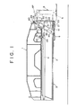
- the jack cylinder 5 is attached to the front end of the extensible beam so that it is swingable longitudinally (widthwise) of the machine; when the outrigger is not used (during travel on a highway), said cylinder is drawn from its vertical position established by its own weight toward the beam 3, while turning around the axis of the pivot at its upper end, until it is stored in an inclined state in said beam 3, as shown in Fig. 1.
- a projection 37 is formed on the upper end of the jack cylinder 5, i.e., on the front end of the rod 52, while a transversely and horizontally extending pusher pin 39 is installed in a bracket 40 at a position opposed to said projection 37.
- the numeral 23 denotes a collar fitted on said pusher pin 39.
- the projection 37 on the jack cylinder 5 will abut against the pusher pin 39 immediately before the end of a stroke for drawing the beam 3 during extensible beam storage operation and will be pushed by the pusher pin 39 on the remaining stroke, so that the jack cylinder 5 will be automatically swung into said inclined stored position.
- abutment surface of the projection 37 associated with the pusher pin 39 is substantially L-shaped, as shown, to provide for stabilized abutted condition.
- Locking means for holding the jack cylinder 5 in its vertical position will now be described.
- Projections 55 are provided on transversely opposite sides of the cylinder tube 51 of the jack cylinder 5, extending from the upper end of said tube to a predetermined position on the lower portion of said tube.
- the front inner lower surface portion of the jack cylinder 5 has fixed thereto, on transversely opposite sides, guides 31 extending along an arc having its center of curvature located at the pivot 53 of the jack cylinder 5, with the lower end surfaces of said projections 55 on the jack cylinder 5 being opposed to said guides 31.
- the guides 31 are each formed with an engaging recess having a width capable of receiving the associated projection 55, the position of said.engaging recesses being such that a perpendicular dropped from the pivot 53 of the jack cylinder 5 coincides with the centerline of the recesses.
- the projections 55 are positioned above said engaging recesses 32, so that extension of said cylinder causes the projections 55 to fit in the engaging recesses 32, as shown in Figs. 1 and 2.
- notches 21 and 33 are formed in the front end lower surfaces of the fixed box 2 and extensible beam 3 to allow the swing movement of the jack cylinder 5 .
- the numeral 25 denotes a locking hole in the front upper surface of the fixed box and 28 denotes a locking hole in the front upper surface of the extensible beam 3, said locking holes 25 and 28 being adapted to receive a locking pin 22 to lock the extensible beam 3 in its stored position.
- the float 6 is pivotally connected to the cylinder tube 56 of the jack cylinder 5 by pins 56 extending from opposite sides of the lower end portion of the cylinder tube and received in vertically elongated openings 62 (Fig. 3) formed in float attaching seats 61.
- the extensible beam 3 is extended outwardly laterally of the machine and the jack cylinder 5 is vertically extended, as shown in Figs. 2 and 3, to bring the float 6 into contact with the ground while floating the machine to be ready for various types of work.
- the jack cylinder 5 since the projections 55 on the cylinder tube 51 engage the engaging recesses 32 of the guides 31 on the extensible beam 3, as described above, the jack cylinder 5 is locked in its vertical position and is thereby prevented from swaying or toppling during operation.
- the jack cylinder 5 When it is desired to store the outrigger, the jack cylinder 5 is contracted to disengage said projections 55 from the engaging recesses 32 and then the extensible beam 3 is drawn into the fixed box 2 for storage therein.
- the projection 37 on the upper end of the jack cylinder abuts against the pusher pin 39, so that on that portion of the stroke which starts with this abutment and ends with completion of extensible beam storage, the projection 37 is pushed by the pusher pin 39 outwardly laterally of the machine, whereby the jack cylinder 5 is swung toward the extensible beam 3 around the axis of the pin 53, until it is stored in its inclined position in the beam 3, as shown in Fig. 1.
- the float 6 comes in intimate contact with the lower surface of the fixed box 2 while maintaining its horizontal position.
- the jack cylinder 5 is firmly held in its inclined stored position by the abutting action between the projection 37 and the pusher pin 39, as described above, this embodiment makes doubly sure by inserting a locking pin 97 into a locking hole 58 formed in a bracket 49 mounted on the upper portion of the cylinder tube of the jack cylinder 5 and into a lacking hole 35 formed in the front end of the extensible beam, thus doubly locking the jack cylinder in its inclined stored position.
- this outrigger device adapted to draw the jack cylinder 5 toward the extensible beam 3 while turning it around the axis of the pivot at its upper end until it is stored in its inclined position in said beam 3 when the device is not used, as described above, it is seen that when the jack cylinder 5 is brought to its vertical position to be ready for operation, said cylinder 5 causes the extensible beam 3 to project downwardly or, in other words, the jack cylinder 5 can be projected downwardly of the machine to reduce the distance from the ground, so that the cylinder 5 is required to have shorter stroke for floating the machine than in the conventional outrigger device.
- the overall length of the" jack cylinder can be reduced by the amount corresponding thereto.
- the outrigger device of the invention the combined effects of (1) the capability of reducing the overall length of the jack cylinder 5 and (2) the capability of projecting the cylinder 5 downwardly of the machine enables the amount of projection of the jack cylinder 5 above the machine to be greately reduced as compared with the conventional device.
- the jack cylinder 5 interfering with pile driving and other proximity work, as in the .past, this being very advantageous from the standpoint of doing work.
- the positional change of the jack cylinder 5 is effected in such a manner that its change to the vertical position is effected by its own weight and its change to the inclined stored position is effected by the abutting action between the projection 37 on the cylinder 5 and the pusher pin 39 on the fixed box 2, it is not necessary to provide a hydraulic cylinder or other exclusive- purpose drive source for the positional change of the jack cylinder 5. Accordingly, the related construction is very simple, the cost is low, and extra operations are not required.
- the locking means for locking the jack cylinder 5 in its vertical position is not limited to the one shown in the embodiment; for example, locking pins adapted to resiliently pop in and out may be installed on the transversely opposite surfaces of the front end portion of the extensible beam 3 so that they may be automatically engaged in locking holes formed in the jack cylinder 5.
- a locking pin may be manually inserted into locking holes formed in the jack cylinder 5 and extensible beam 3.
- the jack cylinder 5 while the jack cylinder 5 is installed at the front end of the extensible beam, with the cylinder tube 51 down, it may, of course, be installed so that the cylinder tube 51 is up, as in the past.
- the jack cylinder is drawn toward the beam while turning around the axis of the pivot at its upper end until it is stored in its inclined position in the beam, the amount of projection of the jack cylinder above the machine can be reduced as compared with the conventional device, which is advantageous to pile driving and other proximity work. Further, since the float can be received within the machine width, it is no longer necessary to remove the float for each travel on a highway, thus allowing the float diameter to be increased so as to improve safety during outrigger operation.
- the positional change of said jack cylinder to its inclined stored position is automatically effected by the abutting action between the projection on the upper end of said cylinder and the fixed box without using any special drive source, while the change from this inclined stored position to the vertical position is effected by the weight of the cylinder.
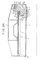
- an extensible cylinder 4 has a cylinder tube 41 whose proximal end is pivotally connected to the inner surface of a fixed box 2 by a horizontal shaft 42 extending transversely of the traveling body, so that said cylinder 4 is swingable in a vertical plane with respect to the fixed box 2.
- the front end of the rod 43 of said extensible cylinder 4 is pivotally connected to a link 54 extending from the jack cylinder 5 by a horizontal shaft 44 likewise extending transversely.
- the extensible cylinder 4 and jack cylinder 5 are interlocked so that in the early stage of extension of the extensible cylinder 4, said cylinder 4 pushes the jack cylinder 5 outwardly laterally of the extensible beam while downwardly turning around the axis of the horizontal shaft 42, while in the early stage of contraction of the extensible cylinder 4, said cylinder 4 pulls the jack cylinder 5 inwardly laterally of the extensible beam while turning it upwardly around the axis of the horizontal shaft 42.
- the inner surface of the extensible beam 3 has fixed thereto on one or both of the transversely opposite sides thereof a stop or stops 17 against which a projection or projections 37 formed on one or both of the transversely opposite sides.
- Projections 55 are provided on the transversely opposite sides of the cylinder tube 51 of the jack cylinder 5, extending from the upper end of said tube to a region close to the lower end. Each projection 55 is stepped so that its outer half 55a disposed adjacent the machine width projects to a greater extent than its inner half 55b (said outer half 55a and said inner half 55b being hereinafter referred to as the high land and the low land, respectively).
- blocks 34 and 63 are fixed to the transversely opposite surfaces of the front end portion of the extensible beam 3 and engaging recesses 32 are defined between said blocks 34 and 63.
- the engaging recesses 32 are so positioned that they will underlie the high lands 55a of the projections 55 on the jack cylinder 5 when said cylinder 5 assumes its vertical contracted position, the width of said recesses being such that the recesses are engageable by the high lands 55a.
- the high lands 55a of the projections 55 will enter the engaging recesses 32 from above and engage the same.
- a locking pin 7 is installed in one of the transversely opposite lower surface regions of the front end portion of the extensible beam 3 through a compression coil spring 71 so that it is capable of reciliently entering and leaving the extensible beam 3.
- the end of the locking pin 7 projecting outside the extensible beam 3 is formed with a vertically extending long head 72, which engages the outer surfaces of a pair of cams 8 vertically spaced a predetermined distance apart from each other and fixed on the lower outer surface region of the front end portion of the fixed box 2.
- the outer surface of each cam is formed with an inclined surface 81 downwardly sloping toward the front end of the fixed box 2.
- the head 72 of the locking pin 7 slides along the cam surfaces 8l,.causing the locking pin 7 to project into the extensible beam 3 until the front end of said locking pin 7 abuts against the low land 55b of the associated projection 55 on the jack cylinder 5, which is in its vertical contracted positoin.
- This abutting engagement of the locking pin 7 with the projection low land 55b prevents the jack cylinder 5 in its vertical contracted position from swinging inwardly of the extensible beam.
- notches 21 and 33 are formed in the front lower surface regions of the fixed box 2 and extensible beam 3 to allow the swing movement of the jack cylinder 5.
- the numeral 22 denotes a locking pin for locking the extensible beam 3 in the stored state.
- the float 6 is installed for swing movement longitudinally of the machine, by pins 56 projecting from the transversely opposite sides of the lower end of the cylinder tube 51 of the jack cylinder 5 and received in elongated openings 62 (Fig. 8) formed in float attaching seats 61.
- the extensible cylinder When the outrigger is used, the extensible cylinder is extended from the state shown in Fig. 5 to cause the extensible beam 3 to extend outwardly laterally of the machine, as shown in Fig. 9, and then the jack cylinder 5 is extended in its vertical position to contact the float with the ground to thereby float the machine to be ready for various types of work.
- the jack cylinder 5 is in the illustrated inclined stored position.
- said cylinder 4 turns downwardly around the axis of the horizontal shaft 42 while pushing the link 54 of the jack cylinder 5 by the rod 45.
- the jack cylinder 5 is turned around the axis of the horizontal pin 53 to assume its vertical position, whereupon the extending force of the extensible cylinder 4 is applied to the extensible beam 3 through the stops 17, thereby starting extension of said beam 3.
- the arrangement for transmitting the extending force of the extensible cylinder 4 to the extensible beam 3 from the time the jack cylinder 5 assumes its vertical position is more advantageous than an arrangement wherein the extending force is transmitted to the extensible beam 3 through the jack cylinder 5 continuously even after the jack cylinder 5 assumes its vertical position, from the standpoint of protection of the jack cylinder 5 since the high extending force does not acts on the cylinder 5.
- the jack cylinder 5 Upon completion of extension of the extensible bema, the jack cylinder 5 is extended to bring the high lands 55a of the projections 55 into engagement with the engaging recesses 32 formed in the inner surface of the extensible beam 3, whereby the cylinder 5 is locked in its vertical extended position and thereby prevented from swaying or toppling during operation.
- the jack cylinder 5 is contracted to disengage the high lands 55a from the engaging recesses 32, and in this state the extensible beam.3 is drawn into the fixed box 2 for storage therein.
- the jack cylinder 5 automatically swings for a change from its vertical to inclined storage position, whereupon storage of the extensible beam 3 is started.
- the float 6 comes in intimate contact with the lower surface of the fixed box 2, being held horizontal.
- this outrigger device arranged so that the jack cylinder 5 is stored in its inclined state in the extensible beam 3 at the time of outrigger stor-ge, as described above, when the jack cylinder 5 is brought to its vertical position to be ready for operation, said cylinder 5 projects downwardly of the extensible beam 3 or, in other words, the jack cylinder 5 is projected downwardly to reduce the distance from the ground, so that the required stroke for said cylinder to float the machine is reduced as compared with the conventional device.
- the overall length of the jack cylinder 5 can be reduced by the corresponding amount.
- the jack cylinder 5 is adapted to be projected in its vertical position downwardly of the machine, the amount of projection of said cylinder above the machine can be correspondingly reduced.
- the present device since the positional change of the jack cylinder 5 between the vertical position and the inclined stored position automatically and forcibly effected by utilizing the extension and contraction of the extensible cylinder 4, the reliability of the positional change of the jack cylinder'is high and there is no need to perform extra operations.
- the extensible cylinder 4 is attached to the fixed box 2 and interlocked to the jack cylinder 5 so that it may swing in operative association with the jack cylinder 5, the construction is simpler than a construction wherein an unswignable extensible cylinder and a swingable jack cylinder are interlocked to each other through an intermediate transmission mechanism, such as a link meachanism; there is no danger of causing troubles, such as the positional change of the jack cylinder 5 being unnecessarily accelerated by the accelerating action of such intermediate transmission mechanism.
- an intermediate transmission mechanism such as a link meachanism
- the jack cylinder 5 may be installed with the cylinder tube 51 up, as in the conventional arrangement.
- the extensible cylinder 4 will be connected to the cylinder tube 51 of the jack cylinder 5; the two components 4 and 51 may be directly pivotally connected together without using a link such as the link 54 in the above embodiment.
- the locking means for locking the jack cylinder 5 in its vertical extended position is not limited to the above embodiment; for example, locking pins adapted to resiliently come in and out may be provided in the transversely opposite surfaces of the front end portion of the extensible beam 3 so that said locking pins may be automatically engaged in locking holes formed in the jack cylinder 5. Alternatively, a locking pin may be manually inserted into locking holes formed in the jack cylinder 5 and extensible beam 3.
- an auxiliary extensible cylinder 92 has a cylinder tube 92a pivotally connected at its distal end to an intermediate surface region 85 of an extensible beam 3 by horizontal shaft 90 extending transversely of the traveling body, whereby the cylinder 92 is attached to the extensible beam 3 so taht it is swingable in a vertical plane.
- the front end of the rod 91 of the auxiliary cylinder 92 is pivotally connected to a link 54 projecting from a jack cylinder 5 by a horizontal shaft 44 likewise extending transversely. That is, the auxiliary extensible cylinder 92, which has exactly the same functioning as that of the extensible cylinder 4 associated with the jack cylinder 5 of Fig.
- the extensible cylinder 4 is connected at the distal end of its cylinder tube 41 to a fixed point.15 on the inner surface of the fixed box 2 and is connected to a connecting rod 11 disposed at the end of the rod 43 of the cylinder nearer to the jack cylinder 5, the arrangement being such that the extending thrust of the rod 43 of the extensible cylinder 4 acts directly on the extensible beam 3 from the time the jack cylinder 5 assumes its vertical position under the thrust of the auxiliary extensible cylinder 92, thereby effecting extension of the extensible beam 3.
- the auxiliary extensible cylinder 92 serves to effect only the positional change of the jack cylinder 5 from its vertical to stored position and vice versa, while the extensible cylinder 4 serves to effect only the extension of the extensible beam 3. Therefore, part of the extension of the extensible cylinder compensates for the amount consumed for the positional change of the jack cylinder to its vertical position,-thereby making it possible to further extend the extensible beam.
- the large diameter of the outrigger device is particularly effective in increasing the stability of the machine frame.
- a jack cylinder 5 is installed at the front end of an extensible beam 3, with a cylinder tube 51 up and a rod 52 down, which is reverse to the conventional positioning, the rod end being pivotally connected to the extensible beam 3 by a horizontal pin 53. extending transversely of the machine.
- the jack cylinder 5 is attached to the front end of the extensible beam so that it is swingable around the axis of the pivot at its upper end longitudinally (widthwise) of the machine.
- the cylinder 5 is drawn from its vertical position inwardly laterally of the extensible beam 3 while turning around the axis of the pivot at its upper end until it is stored in its inclined position in said beam 3, as shown in Fig. 11.
- the jack cylinder 5 is provided with a link 54 projecting downwardly from the upper end of said rod, the lower end of said link 54 being pivotally connected to the front end of the rod 43 of the extensible cylinder 4 by a tarnsversely extending horizontal shaft 44.
- the extensible cylinder 4 and jack cylinder 5 are interlocked to each other so that in the early stage of extension of the extensible cylinder 4, said cylinder 4 pushes the jack cylinder 5 outwardly laterally of the extensible beam while turning downwardly around the axis of the horizontal shaft 42, while during contraction of the extensible cylinder 4, reversely, said cylinder 4 pulls the jack cylinder 5 inwardly laterally of the extensible beam while turning upwardly around the axis of the horizontal shaft 42.
- the upper end of the link 54 at the jack cylinder 5 is integrally formed with a locking arm 67 extending through an opening 30 in the front upper surface region of the extensible beam 3 to enter the front end portion of the fixed box 2 with the extensible beam in its stored position.
- a transversely extending horizontal locking rod 20 In the front end portion of the fixed box 2 which said locking arm 67 enters, there is fixed a transversely extending horizontal locking rod 20, so that when the jack cylinder 5 assumes its inclined stored position, said locking arm 55 engages said locking rod 20 in the beam extensing direction, but when the jack cylinder 5 is turned into its vertical position, the locking arm 67 is disengaged from the locking rod 20.
- Engaging projections 55 are provided on the transversely opposite sides of the cylinder tube 51 of the jack cylinder 5, extending from the upper end of said tube to a region close to the lower end.
- the transversely opposite inner surfaces of the front end portion of the extensible beam 3 are provided with guide projections 32 along the path of movement described by the lower end surfaces of said projections 55 during swing movement of the jack cylinder 5.
- Each guide projection 32 has at its initial end (nearer to the inner lateral end of the beam) a stop portion 32a which comes in adjacent opposed relation to the lower end surface of the associated engaging projection 55 when the jack cylinder 5 is stored in its inclined position, so that when the jack cylinder 5 in its inclined stored position is operated for extension by mistake, the engaging projections 55 strike the stop portions 32a to thereby prevent extension of the jack cylinder 5.
- the guide projection is provided with an engaging recess 32b adjacent the terminal end thereof.
- the engaging recesses 32b are so positioned that they are opposed to the engaging projections 55 on said jack cylinder 5 when the latter assumes its vertical contracted position, the width of said engaging recesses being such that they are engageable by said projections 55.
- the engaging projection 55 will engage the engaging recesses 32b from above.
- the lower ends of said projections 55 and the upper open portions of said engaging recesses are formed with inclined guide surfaces 32 and 32c.
- the terminal end portion including the engaging recess 32b may be formed separately from the remaining portion and removably attached to the latter as by bolts to enable replacement in case of wear.
- a locking pin 7 is installed in one of the transversely opposite lower surface regions of the front end portion of the extensible beam 3 through a compression coil spring 71 so that it resiliently comes in and out of the extensible beam 3.
- the end of the locking pin projecting outside the extensible beam 3 is formed with a vertically elongated head 72, which engages the outer surfaces 8 of a pair of cams 8 vertically spaced a predetermined distance apart from each other and fixed to the lwoer outer surface region of the front end portion of the fixed box 2.
- each cam is formed with an inclined cam surface 81 which, when seen in plan view, slopes down toward the front end of the fixed box 2.
- the numeral 18 denotes a groove for leading the locking pin head 72 into the outside of the fixed box 2. Further, the lower surface of the front end portions of the fixed box 2 and extensible beam 3 are formed with notches 21 and 33 to allow the swing movement of the jack cylinder 5.
- the numeral 83 denotes a locking pin for locking the extensible beam 3 in its stored state.
- the float 6 is swingably installed by pins 56 projecting from the transversely opposite sides of the lower end portion of the cylinder tube 51 of the jack cylinder 5 and inserted in elongated openings 62 formed in float attaching seats 61.
- the extensible cylinder 4 When the outrigger is used, the extensible cylinder 4 is extended from its state shown in Fig. 11 to extend the extensible beam 3 outwardly laterally of the machine, as shown in Fig. 17 and then the jack cylinder 5 is extended in its vertical position to bring the float 6 into contact with the ground to float the machine to be ready for various types of work.
- the jack cylinder 5 is in the illustrated inclined storage position.
- said cylinder 4 starts to extend to cause extension of the extensible beam 3, said cylinder 4, while turning downwardly around the axis of the horizontal shaft 42, as described above, pushes the link 54 of the jack cylinder 5 by the rod 43.
- the jack cylinder 5 is turned around the axis of the horizontal pin 53 to assume its vertical position, whereupon the extending force of the extensible cylinder 4 is applied to the extensible beam 3, starting extension of the beam 3.
- the jack cylinder 5 Upon completion of extension of the extensible beam, the jack cylinder 5 is extended to cause the engaging projections 55 to engage the engaging recesses 32b of the guide projections 32 on the extensible beam 3, whereby the cylinder 5 is locked in its vertical extended position and prevented from swaying or toppling during operation.
- the jack cylinder 5 When it is desired to store the outrigger, the jack cylinder 5 is contracted to disengage the engaging projections 55 from the engaging recesses 32b and then the extensible beam 3 is drawn into the fixed box 2 for storage therein.
- the contraction of the extensible cylinder 4 pulls the jack cylinder 5 inwardly laterally of the extensible beam, but the jack cylinder 5 is prevented from swinging by the locking pin 7. Therefore, during beam storage stroke, the jack cylinder 5 is held in its vertical contracted position and the contracting force of the extensible cylinder 4 is transmitted to the extensible beam 3 through the jack cylinder 5 and locking pin 7.
- the head 72 of the locking pin 7 slides along the cam surfaces 81 of the cams 8, thus pulling the locking pin 7 outwardly of the beam and releasing said pin 7 from the engaging projection 55 on the jack cylinder 5. Since this unlocks the jack cylinder 5, which is in its vertical position, the jack cylinder 5 is pulled by the extensible cylinder 4 from the time the storage of the extensible beam 3 is completed, automatically changing from its vertical to inclined position, finally assuming the state shown in Fig. 11. At this instant, the float 6 comes in contact with the lower surface of the fixed box 2 while it is horizontal.
- the present device has the following merits concerning prevention of malfunction.
- the first problem is about malfunction of the jack cylinder.
- the jack cylinder 5 is operated for extension by mistake before the extending operation of the extensible beam 3.
- this causes trouble to the extension of the extensible beam 3 and to the subsequent operation, making it impossible to install the outrigger.
- the engaging projections 55 on the jack cylinder 5 abut against the stop portions 32a of the initial end 32a of the guide projections 32 on the extensible beam 3, it is possible to prevent the jack cylinder 5 from extending by mistake.
- the extensible beam 3 is operated for extension without the operator's knowledge of the situation where the engaging projections are pressed against the stop portions 32a.
- the resisting force due to the forced contact between the engaging projections 55 and the stop portions 32a (hereinafter referred to simply as the resisting force) is lower than the beam extending thrust due to the extensible cylinder 4 (hereinafter referred to simply as the extending thrust)
- the extending thrust overcomes the resisting force and forces the jack cylinder 5 to swing to its vertical position.
- said resisting force against the swing of the cylinder 5 includes the rusting of the pivot around which it swings.
- the stop portions 32a for preventing extension of the jack cylinder 5 in its inclined stored position have been provided as part of the guide projections 32, but the stops 32 may be provided singly, not as the guide projections.
- the jack cylinder 5 is installed with the cylinder tube 51 down and the rod 52 up, which is reverse to the conventional positioning, since the rod 51 is hidden in the extensible beam 3, likely damage to the rod 52 and incidental oil leakage and malfunction can be prevented and machining to be applied to the locking means, etc., may be applied to the cylinder tube 51, so that such machining is easy to perform.
- it may be installed with the cylinder tube 51 up, as in the conventional arrangement.
- locking means for locking the jack cylinder 5 in its vertical extended position is not limited to the above embodiment; for example, locking pins adapted to resiliently come in and out may be provided in the transversely opposite surfaces of the front end portion of the extensible beam 3 so that said locking pins may be automatically engaged in locking holes formed in the jack cylinder 5. Alternatively, a locking pin may be manually inserted into locking holes formed in the jack cylinder 5 and extensible beam 3.
- the jack cylinder and extensible beam are respectively provided with projections adapted to be opposed to each other axially of the jack cylinder when the latter is in its inclined stored position, which projections thus constitute a stop mechanism, it is possible to prevent extension of the jack cylinder when the latter is operated for extension by mistake when it is in its inclined stored position. Further, if the jack cylinder becomes incapable of swing, it is possible to prevent extension of the extensible beam by the engaging action between the locking arm provided on the jack cylinder and the locking rod provided in the fixed box, thereby ensuring the proper outrigger extending operation and increasing the reliability of the device.
- the numerals 2, 3 and 12 denote extensible beams telescopically fitted together.
- Extensible cylinders 4 and 4P are provided for extending said extensible beams, and a jack cylinder 5 is swingably provided at the front end of the foremost beam 3.
- the extensible cylinder 4P has a cylinder tube 4Q fixed at its proximal end to the inner surface of a fixed box 2 at a fixed point 15, and a cylinder rod 13 connected at its front end to the outer extensible beam 12 by a connecting member 11.
- the extensible beam 4 has a cylinder tube 41 pivotally connected at its proximal end to the inner surface 86 of the extensible beam 12 by a horizontal shaft 84 extending transversely of the traveling body, whereby the cylinder 4 is attached to the extensible beam 12 so that it is swingable in a vertical plane.
- the front end of the rod 43 of the extensible cylinder 4 is pivotally connected to a link 54 projecting from the jack cylinder 5 by a transversely extending horizontal shaft 44. That is, the arrangement is such that the extensible cylinder 4 which was pivotally connected at 42 to the fixed box 2 in Fig. 6 is pivotally connected at 84 to the inner surface of the extensible beam 12, instead of being pivotally connected to the fixed box 2.
- the thrust of the front extensible cylinder 4 moves the jack cylinder 5 to its vertical position, and then the extensible beam 3 starts to advance. Meanwhile, the forward movement of the extensible cylinder rod 13 of the extensible cylinder 4P causes the extensible beam 12 connected thereto by the connecting member 11 to advance toward the front end. Meanwhile, the foremost beam 3 advances under the thrust of the rod 43 of the extensible cylinder 4 pivotally connected to the inner surface of the extensible beam 12. Therefore, the extensible beams 3 and 12 can be extended the sum of the amounts of forward travel the extensible- cylinders 43 and 13. It is so arranged that said length of extension can be obtained by adjusting the amounts of forward travel of the cylinder rods 43 and 13.
- the amount of extension of the extensible beam assembly is greately increased and the large inner diameter of the outrigger device is particularly effective in increasing the stability of the machine frame in the case of handling heavy objects.
- an extensible cylinder 4 is connected at the proximal end of its cylinder tube 41 to the inner surface of a fixed box 2 and at the front end of its rod 43 to the front inner surface region of an extensible beam 3, so that extension and contraction of the extensible cylinder 4 enable the extensible beam 3 to be extended from and stored inthe fixed box 2.
- the rod end of the extensible cylinder 4 and the extensible beam 3 are interconnected in the following manner.
- a backet 40 is fixed to the rod end of the extensible cylinder 4, said bracket 40 being formed with an elongated opening 45 extending in the direction of extension and contraction of said cylinder. Further, a horizontal pin 29 extending transversely of the machine is fixed in the interior of the front end portion of the extensible beam 3, said pin 29 being inserted in the elongated opening 45 so that it is movable within the range of constant length.
- the rod 43 of the extensible cylinder 4 is connected to the extensible beam 3 so that within the range of constant length it is capable of extension and of free movement (lost motion) in the storing direction.
- a pin 56 extending transversly of the! machine is fixed to the front end of the bracket 40 fixed to the rod end of the extensible cylinder 4, said pin 56 being engaged in an elongated opening 46 formed in a bracket 49 fixed to the outer surface of the cylinder tube 51 of the jack cylinder 5.
- the elongated opening 46 extends axially of the jack cylinder 5, and the extensible cylinder 4 and jack cylinder 5 are operatively interconnected through said elongated opening 46 and pin 56.
- a locking pin 7 is installed in one of the transversely opposite lower surface regions of the front end portion of the extensible beam 3 through a compression coil spring 71 so that it is capable of resiliently entering and leaving the extensible beam 3.
- the end of the locking pin 7 projecting outside the extensible beam -3 is formed with a vertically extending long head 72 engaged with the outer surfaces of a pair of cams 8 spaced a predetermined distance apart from each other and fixed to the lower outer surface region of the front end portion of the fixed box 2.
- the outer surfaces of the cams are each formed with an inclined cam surface 81 sloping downwardly toward the front end of the fixed box 2, so that as the extensible beam 3 extends, the head 72 of the locking pin 7 slides along the cam surfaces 81, causing the locking pin 7 to project into the extensible beam 3.
- a locking plate 57 having a locking hole 77 is fixed to the region of the outer surface of the cylinder tube 51 of the jack cylinder 5 opposed to the locking pin 7, so that when the jack cylinder 5 assumes its vertical position, the locking pin 7 faces the locking hole 77 of the locking plate 57 and projects into the extensible beam until its front end engages the locking hole 77. This engagement of the locking pin 7 with the locking hole 77 prevents the jack cylinder 5 in its vertical contracted position from swinging inwardly laterally of the beam.
- notches 21 are formed in the front lower surface regions of the fixed box 2 and extensible beam 3 to allow the swing movement of the jack cylinder 5.
- the numeral 22 denotes a locking pin for locking the extensible beam 3 in its stored position
- 83 denotes a stop for defining the storage position of the beam 3. From the standpoint of safety it is desirable to provide the proximal end of the extensible beam 3 and the front end of the fixed box with stops (not shown) for limiting the amount of extension of said beam 3 to a constant value.
- the float 6 is swingably installed by pins 62 projecting from the transversely opposite sides of the lower end portion of the rod 52 of the jack cylinder 5 and inserted in elongated holes 62 formed in float attaching seats 61 (Fig. 19).
- the extensible cylinder 4 When the outrigger is used, the extensible cylinder 4 is extended from its state shown in Fig. 19 to extend the extensible beam 3 outwardly laterally of the machine, as shown in Fig. 23 and then the jack cylinder 5 is extended in its vertical position to bring the float 6 into contact with the ground to float the machine to be ready for various types of work.
- the rod 43 of the cylinder 4 performs lost motion (sole motion) within the range of the distance of free movement of the pin 29 in the elongated opening 45 in the bracket 40, and during the lost motion stroke of the rod 43 the jack cylinder 5 is pushed by said rod 43 and thereby automatically and forcibly moved from its inclined stored position to its vertical position shown in Fig. 2a.
- the pin 29 completes its movement in the elongated opening 45, so that extension of the extensible beam 3 is then started.
- the jack cylinder 5 when the jack cylinder 5 is extended to bring the float into contact with the ground after the extension of the extensible beam, the jack cylinder 5 is locked in its vertical position by the extensible cylinder 4 and said locking mechanism, being prevented from swaying or toppling during operation.
- the extensible beam 3 When it is desired to store the outrigger, with the jack cylinder 5 contracted, the extensible beam 3 is drawn into the fixed box 2 for storage therein.
- the rod 43 of the extensible cylinder 4 tends to move alone in the direction opposite to that of extension, but since the jack cylinder 5 is prevented from swinging toward its inclined stored position by the locking pin 7, the extensible beam 3 starts to move as soon as the rod 43 of the extensible cylinder moves.
- the head 72 of the locking pin 7 climbs up the cam surfaces 81 of the cams 8, releasing said locking pin 7 from the locking hole 77 and thereby unlocking the jack cylinder 5 in its vertical contracted position.
- the rod 43 of the extensible cylinder 4 moves alone in the direction opposite to that of extension, during which time the jack cylinder 5 is pulled by the rod 43 and thereby automatically changes from its vertical position shown in Fig. 20 to its inclined stored position shown in F ig. 43.
- the float 6, in the horizontal state contacts the lower surface of the fixed box 2.
- jack cylinder 5 is attached to the front end of the extensible beam with the cylinder tube 51 up, but it may be pivotally connected to the front end of the extensible beam in reverse, with the cylinder tube down and the rod 52 up.
- Such arrangement is advantageous in that since the rod 52 is hidden in the beam 3, likely damage to the rod 52 and incidental oil leakage and malfunction can be prevented.
- a bracket 40 is fixed to the rod end of an extensible cylinder 4 and formed with an elongated opening 45 extending in the direciton of extension and contraction of said cylinder.
- An extensible beam 3 has two horizontal pins 29 and 50 internally fixed thereto in its front end portion, the distance between said pins being smaller than the length of said elongated opening 45, said pins 29 and 50 being inserted in said elongated opening 45 so that they are movable along the latter in the range of constant length.
- the rod 43 of the extensible cylinder 4 is connected to the extensible beam 3 so that it is capable of extension in the range of constant length and free movement (lost motion) in the storing direction.
- the bracket 40 fixed to the rod end of the extensible cylinder 4 is operatively connected to a jack cylinder 5 successively through a link attaching seat 48 fixed to the lower end of said bracket, a link mechanism 10 consisting of first and second links 79 and 80, and a link attaching seat 78 fixed to the front end of the rod of the jack cylinder 5.
- the first link 79 of the link mechanism 10 is doglegged and pivotally connected at its middle to the extensible beam 3 by a fixed pin 79.
- the second link 80 is pivotally connected to the first link 79 by a movable pin 73 so that the links are turnable relative to each other.
- the first link 79 and the link attaching seat 48 are pivotally connected together through an elongated opening 46 so as to convert the linear motion of the rod 43 into the rotary motion of the first link 79.
- Locking means for locking the jack cylinder 5 in its vertical extended position will now be described.
- Projections 55 are formed on the transversely opposite sides of the cylinder tube 51 of the jack cylinder 5, extending from the upper end of said tube to a region close to the lower end. Each projection 55 is stepped so that the outer half 55a disposed adjacent the machine width projects to a greater extent than its inner half 55b (said outer half 55a and said inner half 55b being hereinafter referred to as the high land and the low land, respectively).
- blocks 34 and 63 are fixed to the transversely opposite surfaces of the front end portion of the extensible beam 3 and engaging recesses 32 are defined between said blocks 34 and 63.
- the engaging recesses 32 are so positioned that they will underlie -the high lands 55a of the projections 55 on the jack cylinder 5 when said cylinder 5 assumes its vertical contracted position, the width of said recesses being such that the recesses are engageable by the high lands 55a.
- the high lands 55a of the projections 55 will enter the engaging recesses from above and engage the same.
- a locking pin 7 is installed in one of the transversely opposite lower surface regions of the front end portion of the extensible beam 3 through a compression coil spring 71 so that it is capable of resiliently entering and leaving the extensible beam 3.
- the end of the locking pin 7 projecting outside the extensible beam 3 is formed with a vertically extending long head 82, which engages the outer surfaces of a pair of cams 8 vertically spaced a predetermined distance apart from each other and fixed on the lower outer surface region of the front end portion of the fixed box 2.
- the outer surface of each cam is formed with an inclined surface 81 downwardly sloping toward the front end of the fixed box 2.
- the head 82 of the locking pin 7 slides along the cam surfaces 81, causing the locking pin 7 _to project into the extensible beam 3 until the front end of said locking pin 7 abuts against the low land 55b of the associated projection 55 on the jack cylinder 5, which is in its vertical contracted position.
- This abutting engagement of the locking pin 7 with the projection low land 55b prevents the jack cylinder 5 in its vertical contracted position from swinging inwardly of the extensible beam 3.
- notches 21 and 33 are formed in the front lower surface regions of the fixed box 2 and extensible beam 3 to allow the swing movement of the jack cylinder 5.
- the numeral 24 denotes a locking pin for locking the extensible beam 3 in its stored state
- 83 denotes a stop for defining the storage position of the beam 3. From the stanpoint of safety it is desirable to provide the proximal end of the extensible beam 3 and the front end of the fixed box 2 with stops (not shown) for limiting the amount of extension of said beam 3 to a constant value.
- a projection 37 is formed on the upper end of the jack cylinder 5, i.e., on the front end of the rod 52,-while a transversely extending horizontal pusher pin 39 is fixed to the front upper portion of a fixed box 2 at a level corresponding to that of said projection through the intermediary of a -bracket 40.
- the numeral ' 23 denotes a collar fitted on said pusher pin 39.
- the projection 37 on the jack cylinder 5 will abut against the pusher pin 39 immediately before the end of a stroke for drawing the beam 3 during extensible beam storage operation and will be pushed by the pusher pin 39 on the remaining stroke, so that the jack cylinder 5 will be automatically swung into its inclined stored position.
- the abutment surface of the projection 37 associated with the pusher pin 39 is doglegged, as shown, to provide for stabilized abutted condition.
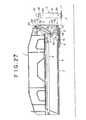
- Projections 55 of U-shaped cross-section are provided on the transversely opposite sides of the cylinder tube 51 of the jack cylinder 5, extending from the upper end of said tube to a predetermined lower position, and a roller 59 is rotatably attached to the lower end of said projection in such a manner as to project downwardly beyond said lower end to some extent.
- the transversely opposite inner surfaces of the extensible beam 3 are integrally formed with cams 98 each having a cam surface 99 on their upper surface, said cams being positioned below said rollers 59.
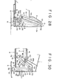
- each cam 99 is formed along an inclined arcuate path which extends to recede from said roller 59 as the jack cylinder 5 moves from its inclined stored to vertical position, or which has its center of curvature located at point 0 2 (Fig. 28) which is spaced from the pivot axis 0 1 of the jack cylinder 5 laterally outside the machine, so that when the jack cylinder 5 is in its inclined stored position, the roller 59 is in contact with the inner end of the cam surface 99.
- the cam surface may not be the described arcuate curved surface but a straight inclined surface extending along said inclined path.
- the portion of the cam 98 extending outwardly from the surface 99 is horizontal and is formed with an engaging recess 32.
- the engaging recess 32 has such a width that it is engageable by the associated projection 55 on the jack cylinder 5, and the recess is so positioned as to be bisected by a perpendicular dropped from the pivot axis O 1 of the jack cylinder 5.
- the projections 55 overlie the engaging recesses 32, and when the jack cylinder 5 is extended in this position, the recesses 55 descend to engage the engaging recesses 32.
- notches 21 and 33 are formed in the front lower surface regions of the fixed box 2 and extensible beam 3 to allow the swing movement of the jack cylinder 5.
- an extensible beam 3 has two horizontal pins 29 and 50 internally fixed thereto in its front end portion, the distance between said pins being smaller than the length of an elongated opening 45, said pins being inserted in said elongated opening 45 so that they are movable within the range of constant length.
- the arrangement is such that the rod 43 of an extensible cylinder 4 is capable of extension within the range of constant length with respect to the extensible beam 3 and of free movement (lost motion) in the storing direction.
- a bracket 40 fixed to the rod end of the extensible cylinder 4 is operatively connected to a jack cylinder 5 successively through a link attaching seat 48 fixed to the lower end of said bracket, a link mechanism consisting of first and second links 79 and 80, and a link attaching seat 78 fixed to the front end of the rod of the jack cylinder 5.
- the first link 79 of the link mechanism is doglegged and pivotally connected at its middle to the extensible beam 3 by a fixed pin 65.
- the second link 80 is pivotally connected to the first link _79 by a movable pin 73 so that the links are turnable relative to each other.
- the first link 79 and the link attaching seat 48 are pivotally connected together through an elongated opening 46 so.as to convert the linear motion of the rod into the rotary motion of the first link 79.
- Locking means for locking the jack cylinder 5 in its vertical extended position will now be described.
- Projections 55 are formed on the transversely opposite sides of the cylinder tube 51 of the jack cylinder 5, extending from the upper end of said tube to a region close to the lower end. Each projection 55 is stepped so that the outer half 55a disposed adjacent the machine width projects to a greater extent than the inner half 55b (said outer half 55a and said inner half 55b being hereinafter referred to as the high land and the low land, respectively).
- blocks 34 and 63 are fixed to the transversely opposite surfaces of the front end portion of the extensible beam 3 and engaging recesses 32 are defined between said blocks 34 and 63.
- the engaging recesses 32 are so positioned that they will underlie the high lands 55a of the projections 55 on the jack cylinder 5 when said cylinder assumes its vertical contracted position, the width of said recesses being such that the recesses are engageable by the high lands 55a.
- the high lands 55a of the projections 55 will enter the engaging recesses from above and engage the same.
- a locking pin 7 is installed in one of the transversely, opposite lower surface regions of the front end portion of the extensible beam 3 through a compression spring 71 so that it is capable of resiliently entering and leaving the extensible beam 3.
- the end of the locking pin 7 projecting outside the extensible beam 3 is formed with a vertically extending long head 82, which engages the outer surfaces of a pair of cams 8 vertically spaced a predetermined distance apart from each other and fixed on the lower outer surface region of the front end portion of the fixed box 2.
- the outer surface of each cam is formed with an inclined cam surface 81 downwardly sloping toward the front end of the fixed box 2.
- the head 82 of the locking pin 7 slides along the cam surfaces 81, causing the locking pin 7 to project into the extensible beam 3 until the front end of said locking pin 7 abuts against the low land 55b of the associated projection on the jack cylinder 5, which is in its vertical contracted position.
- This abutting engagement of the locking pin 7 with the projection low land prevents the jack cylinder 5 from swinging inwardly of the extensible beam 3.
- a pinion 52 is installed at the upper end of a jack cylinder 5, i.e., at the front end of a rod 52 pivotally connected to an extensible beam 3, while a rack 19 is fixed to the front end of a fixed box 2, which rack is adapted to mesh with said pinion from above when the extensible beam 3 is in its stored state.
- the rack 19 meshes with the pinion 47 when the extensible beam 3 is in its state, the meshing force holding the jack cylinder 5 in its inclined stored position.
- the rack 19 meshes with the pinion 47, automatically swinging the jack cylinder 5 from its inclined stored to vertical position and vice versa.
- the top portions of the two outer teeth 19a and 19b of the rack are stepwise cut off.
- Locking means for holding the jack cylinder 5 in its vertical position will now be described.
- Projections 55 are provided on the transversely opposite sides of the cylinder tube 51 of the jack cylinder 5, extending from the upper end of said tube to a predetermined position of the lower portion.
- guides 31 extending along an arcuate curve having its center of curvature located at the axis of the pivot 53 of the jack cylinder 5 are fixed to the transversely opposite lower inner surface regions of the front end portion of the extensible beam 3, with the lower end surfaces of said projections 55 on the jack cylinder 5 being opposed to said guides 31.
- Each guide 31 is formed with an engaging recess 32 whose centerline coincides with a perpendicular dropped from the pivot axis 53 of the jack cylinder 5 and whose width is such that the engaging recess is engageable by the associated projection 55.
- notches 21 and 33 are formed in the front lower surface regions of the fixed box 2 and extensible beam 3 to allow the swing movement of the jack cylinder 5.
- the numeral 25 denotes a locking hole formed in the front upper surface region of the fixed box 2, and 28 denotes a locking hole formed in the front upper surface region of the extensible beam 3.
- a locking pin 22 is inserted in these locking holes 25 and 28 to lock the extensible beam 3 in its stored state.
- the jack cylinder 5 when the outrigger is used, with the extensible beam 3 extended outwardly laterally of the machine the jack cylinder 5 is extended in its vertical position to bring the float 6 into contact with the ground to float the machine to be ready for various types of work.
- the jack cylinder 5 is locked in its vertical position in that the projections 55 on the jack cylinder 5 engage the engaging recesses 32 of the guides 31 on the extensible beam 3, whereby the jack cylinder is prevented from swaying or toppling during operation.
- the present device is so arranged that the swing movement of the jack cylinder 5 between its vertical position and its inclined stored position is effected by the engagement between the pinion 47 on the upper end of the jack cylinder 5 and the rack 19 on the fixed box 2, as described above, there is no need to provide an exclusive drive source, such as a hydraulic cylinder, for swinging the jack cylinder 5, so that the construction is very simple, the cost is low, and extra operations are unnecessary. Further, the change of the jack cylinder 5 from its inclined stored to vertical position and vice versa can be reliably and smoothly effected.
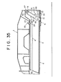
- a rack 19 is fixed to the upper end of the outer side of the cylinder tube 51 of a jack cylinder 5 and at a position where it is opposed to the outer side of an extensible beam 3, said rack being upright with its teeth directed inwardly laterally of the beam.
- a pinion 47 is fitted on a horizontal pin 53 which provides a pivot axis for said cylinder 5, said pinion being fixed to said pin 53 by a bolt 27 with its teeth directed outwardly laterally of the extensible beam.
- the jack cylinder 5 is provided with the rack 19 adapted to move axially of the jack cylinder 5 as the latter extends and contracts, while the extensible beam 3 is provided with the pinion 47 fixed thereto.
- the uppermost tooth 19a of the rack 19 has its top portion cut off so that it is shorter than the other teeth, as shown in Fig. 38; thus, when the jack cylinder 5 is contracted in its vertical position, the uppermost tooth 19a meshes with a particular tooth 47a (hereinafter referred to as the meshing tooth) of the pinion from below in the terminal contraction stage (immediately before completion of contraction).
- Locking means for holding the jack cylinder 5 in its vertical position will now be described.
- Guides 31 extending along an arcuate curve having its center of curvature located at the axis of the pivot 53 of the jack cylinder 5 are fixed to the transversely opposite lower inner surface regions of the front end portion of the extensible beam 3, with the lower end surfaces of projections 55 on the jack cylinder 5 being opposed ⁇ to said guides 31.
- Each guide 31 is formed with an engaging recess 32 whose conterline coincides with a perpendicular dropped from the axis of the pivot 53 of the jack cylinder 5 and whose width is such that the engaging recess is engageable by the associated projection 55.
- the projections 55 overlie the engaging recesses 32, and when said jack cylinder 5 is extended, the projections 55 enter the engaging recesses 32 and engage the same, as shown in Fig. 36 and 37.
- notches 21 and 33 are formed in the front lower surface regions of the fixed box 2 and extensible beam 3 to allow the swing movement of the jack cylinder 5.
- the numeral 25 denotes a locking hole formed in the front upper surface region of the fixed box 2, and 28 denotes a locking hole formed in the front upper surface region of the extensible beam 3.
- a locking pin 22 is inserted in these holes 25 and 28 to lock the extensible beam 3 in its stored state.
- the device is so arranged that a jack cylinder 5 and a rack 16 execute unitary movement only in the terminal stage of contraction and the initial stage of extension of said cylinder 5 but that thereafter the rack 16 is Separated from the jack cylinder 5 and maintained meshing with a pinion 47.
- the preceding embodiment is modified so that an L-shaped rack fitting frame 60 is fixed to the upper end of the outer side of the cylinder tube of the jack cylinder 5 to which the rack 19 of the preceding embodiment was fixed.
- the rack fitting frame 60 has an upwardly opened keyhole-like notch 60a in its upper end.
- the rack 16 is separate from the jack cylinder 5 and its lower portion is formed with a leg 69, the root of which is formed with a stepped hole 70 in which an engaging body 74 is installed through a spring 76 so that said body is capable of resiliently coming-in and out.
- the transversely opposite surfaces of said rack 16 are each formed with a vertically extending groove 75.
- a pair of transversely spaced projections 37 are provided on the upper inner surface region of the front end portion of the extensible beam 3, and pin-receiving holes 37a are formed in said projections 37 in their upper and lower regions. Cylindrical bodies 37b are fixed to the outer surfaces of said projections 37 at the positions where said pin-receiving holes 37a are formed.
- Rack retaining pins 38 are resiliently held in the cylindrical bodies 37b through springs 38a so that their front ends normally project outside the pin-receiving holes 37a.
- a pusher pin 39 is fixed to the front end wall of the extensible beam 3 and below said projections 37.
- the front end surface 39a of the pusher pin 39 and the front end surface 74a of the engaging body 74 are in the form of inclined surfaces complementary to each other.
- the rack 16 and pinion 47 are in mesh all the time, and when the jack cylinder 5 is in its extended position, the rack 16 is separated from the cylinder 5.
- the rack 16 is held in the extensible beam 4 by being nipped between the rack retaining pins 38 fitted in the grooves 75.
- the pusher pin 39 is fitted in the stepped hole 70 of the rack 16 and pushes the engaging body 74 into the stepped hole 70.
- the rack fitting frame 60 engages the rack 16 in the terminal stage of contraction and the contracting force of said cylinder 5, i.e., the lifting force of the cylinder tube 51 is applied to the area of engagement between the rack 16 and the pinion 31.
- the meshing reaction acting on said area of engagement causes the jack cylinder 5 to automatically swing to its inclined stored position, as in the case of the preceding embodiment.
- the pusher pin 39 is disengaged from the stepped hole 70 of the rack 16, so that the engaging body 74 fits in the keyhole-like notch 60a of the rack fitting frame 60, thereby integrally interconnecting the rack 16 and jack cylinder 5.
- the meshing reaction between the rack 16 and the pinion 47 causes the jack cylinder 5 to swing to its vertical position in the initial stage of extension.
- the pusher pin 39 pushes the engaging body 74 into the stepped hole 70 to thereby cancel the connection between the rack 16 and the rack fitting frame 60, and concurrently therewith the rack retaining pins 30 fit in.the grooves 75 of the rack 16. If, therefore, the jack cylinder 5 is subsequently extended, the rack fitting frame 60 is disengaged from the rack 16; thus, the jack cylinder 5 extends while leaving the rack 16 behind.
Landscapes
- Engineering & Computer Science (AREA)
- Mechanical Engineering (AREA)
- Mining & Mineral Resources (AREA)
- Civil Engineering (AREA)
- General Engineering & Computer Science (AREA)
- Structural Engineering (AREA)
- Vehicle Cleaning, Maintenance, Repair, Refitting, And Outriggers (AREA)
Abstract
An outrigger device for wheel-mounted working machines comprises a fixed box (2) secured to a wheel-mounted traveling body (1), an extensible beam (3) storably fitted in the fixed box (2), and a jack cylinder (5) having a float (6) on the lower end thereof and pivotally connected to the front end of the extensible beam (3), the jack cylinder (5) being swingable around the axis of the pivot (53) between a vertical position and a stored position where it is inwardly drawn into the extensible beam (3). Thus, when the outrigger is stored, the jack cylinder (5) is drawn toward the extensible beam (3) while turning around the axis of the pivot (53) at its upper end until it is stored in the beam in an inclined state. This novel arrangement minimizes the amount of projection of the jack cylinder (5) above the machine and makes it possible to receive the float (6) within the machine width while providing protection of the rod (52) of the jack cylinder (5) and increased durability of the cylinder.
Description
- The present invention relates to an outrigger device to be installed on a wheel-mounted working machine, such as a truck crane, roughterrain crane, or wheel shovel and more particularly it relates to an outrigger device for wheel-mounted working machines which is so arranged as to minimize its unnecessary vertical projection and unnecessary extension from the machine width and the amount of projection of the jack cylinder above the machine and to enable the float to be received within the machine width.
- This type of outrigger devices are installed two on each of the front and rear sides of a travelling body, in an H-shaped arrangement as a whole, wherein each outrigger device comprises a fixed box secured to the travelling body, an extensible beam extensibly and storably fitted in said fixed box, and an extensible jack cylinder having a float on the lower end thereof, said jack cylinder being fixed in its vertical position to the front end of said extensible beam.
- This type of conventional outrigger device, however, presents the following problems.
- This type of wheel-mounted working machines have various restrictions imposed on their body construction because they travel on highways. The limited level of the lower surface of the machine above the ground is one of the restrictions. Thus, the jack cylinder of the outrigger device is required to have an extension stroke which is the sum of said machine level and a stroke for lifting the machine above the ground. For this reason, the overall length of the jack cylinder must be increased and this increase adds to the amount of projection above the machine. Thus, since the jack cylinder projects long above the machine, it interfers with pile driving work, loading work with the truck positioned in close proximity to the machine and other so-called proximity work. Thus causing great inconvenience to work. This is the first problem.
- Further, to increase the stability of the machine support, it is desirable,that the extensible beam project laterally outwardly of the machine as long as possible. For this reason, the jack cylinder is so designed as to minimize its unnecessary vertical projection and unnecessary extension in the direction of the width of the machine. With this design, however, the float mounted on the lower end of the jack cylinder will have its substantially outer half projecting outwardly of the machine width. Thus, it has been common practice to remove the float each time the machine travels on a highway, and the removal of the float has been very troublesome. Further, because of this requirement for mounting and dismounting the float, it has been necessary to reduce the float size in order to reduce the float weight, which is disadvantageous from the standpoint of stability of the machine support.
- An object of the invention is to provide an outrigger device for wheel-mounted working machines which is so arranged as to minimize its unnecessary vertical projection and unnecessary extension from the machine width and the amount of projection of the jack cylinder above the machine, while enabling the float to be received within the machine width and providing protection of the jack cylinder and increased durability of the rod of the jack cylinder. Another object is to achieve the construction of such outrigger device in a very simple and rational manner.
- According, the main feature of the invention consists in pivotally connecting the jack cylinder to the front end of the extensible beam to allow it to swing in a vertical plane around the axis of the pivot, and drawing said cylinder toward the extensible beam to store it in an inclined position. Other features reside in the following arrangements.
- An arrangement wherein with the aforesaid main-feature or arrangement as a prerequisite, when it is desired to store the jack cylinder in the extensible beam, a projection formed on the upper end of the jack cylinder is pushed by the front end of the fixed box, whereby the jack cylinder is automatically moved from the vertical position it assumes under its own weight to said inclined stored position and it is held in the latter position.
- An arrangement wherein the change of jack cylinder position from its stored state to its vertical state and vice versa is automatically effected in operative association.withthe extension and contraction of the extensible cylinder.
- An arrangement wherein an auxiliary extension cylinder is provided to increase the extent of extension of the extensible beam.
- An arrangement wherein a stop mechanism is provided to prevent extension and contraction of the jack cylinder in its inclined stored position otherwise caused by malfunction, and wherein extension of the extensible beam is prevented if it becomes impossible for the jack cylinder to swing from its inclined stored position to its vertical position.
- An arrangement wherein said extensible beam is in the form of a multi-stage extensible beam and the swingable jack cylinder is attached to the. foremost extensible beam section.
- An arrangement wherein the change of jack cylinder position in the preceding arrangement is automatically effected in operative association with the extension and contraction of the extensible beam.
- An arrangement wherein the swing movement of the jack cylinder from its vertical position to its inclined storage position is automatically effected by outwardly pushing a projection formed on the upper end of the cylinder by the front end of the fixed box at the time of storage in the extensible beam, while the movement from said inclined storage position to the vertical position can be made not only in a spontaneous manner under the weight of the jack cylinder but also in a forced manner by urging a projection on the outer surface of the jack cylinder against a cam surface on the inner surface of the extensible beam by the extension and contraction of said cylinder.
- An arrangement wherein the jack cylinder is attached to the extensible beam, with the cylinder tube down and the cylinder rod up.
- An arrangement wherein with the above arrangement as a prerequisite, the positional change of the jack cylinder from the inclined storage position to the vertical position and vice versa is automatically effected by a rack and pinion combination..
- An arrangement wherein said positional change is automatically effected by a rack on the jack cylinder cooperating with a pinion on the extensible beam.
- With those and other objects in view, the invention consists in the methods and the construction hereinafter fully described, illustrated in the accompanying drawings, and set forth in the claims hereto appended, it being understood that various changes in the operation, form, proportion and minor details of construction, within the scope of the claims, may be resorted to without departing from the spirit of the invention or sacrificing any of the advantages thereof.
-
- Fig. 1 is a front view, in longitudinal section, of an embodiment of the invention, showing a jack cylinder in its stored position;
- Fig. 2 is a front view, in longitudinal section, of said embodiment in its operative position;
- Fig. 3 is an enlarged section taken along the line III-III in Fig. 2;
- Fig. 4 is an enlarged fragmentary front view, in longitudinal section, of another embodiment of the invention;
- Fig. 5 is a front view, in longitudinal section, of another embodiment of the invention, showing a jack cylinder in its stored position;
- Fig. 6 is a front view, in longitudinal section, of said embodiment in its operative position with the jack cylinder brought to its vertical position;
- Fig. 7 is an enlarged section taken along the line III-III in Fig. 6;
- Fig. 8 is a section taken along the line IV-IV in Fig. 7;
- Fig. 9 is a front view, in longitudinal section, of the device in its operative position;
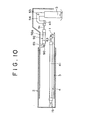
- Fig. 10 is a front view, in longitudinal section, of another embodiment of the invention, showing a jack cylinder in its vertical position;
- Fig. 11 is a front view, in longitudinal section, of another embodiment, showing the jack cylinder in its stored position;
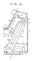
- Fig. 12 is a fragmentary enlarged view of said embodiment;
- Fig. 13 is a view corresponding to Fig. 12, with the jack cylinder moved to its vertical position in operation;
- Fig. 14 is a section taken along the line IV-IV in Fig. 13;
- Fig. 15 is a section taken along the line V-V in Fig. 14;
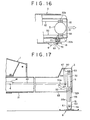
- Fig. 16 is a view corresponding to Fig. 14, showing a position which an extensible beam assumes immediately after it starts to extend;
- Fig. 17 is a front view, in longitudinal section, showing the extended position of an outrigger;
- Fig. 18 is a front view, in longitudinal section, of another embodiment in its operative position with a jack cylinder brought to its vertical position;
- Fig. 19 is a front view, in longitudinal section, of another embodiment of the invention, showing a jack cylinder in its stored position;
- Fig. 20 is a front view, in longitudinal section, of said embodiment, showing the jack cylinder brought to its vertical position;
- Fig. 21 is an enlarged section taken along the line III-III in Fig. 20;
- Fig. 22 is a section taken along the line IV-IV in Fig. 21;
- Fig. 23 is a front view, in longitudinal section, showing the operative position;
- Fig. 24 is a front view, in longitudinal section, of another embodiment of the invention, showing a jack cylinder in its stored position;
- Fig. 25 is a front view, in longitudinal section, showing the jack cylinder brought to its vertical position when the device is used;
- Fig. 26 is a longitudinal section of another embodiment of the invention, showing a jack cylinder in its stored position;
- Fig. 27 is a longitudinal section of another embodiment of the invention, showing a jack cylinder in its stored position;
- Fig. 28 is a view for an explanation of the forced movement of said cylinder form its inclined stored position to its vertical position;
- Fig. 29 is a front view, in longitudinal section, of another embodiment, showing a jack cylinder in its stored position;
- Fig. 30 is a front view, in longitudinal section, showing the jack cylinder brought to its vertical position when the device is used;
- Fig. 31 is a section taken along the line III-III in Fig. 30;
- Fig. 32 is a longitudinal section of another embodiment of the invention, showing a jack cylinder in its stored position;
- Fig. 33 is an enlarged view showing a rack and pinion combination in said embodiment;
- Fig. 34 is a view corresponding to Fig. 33, showing an extensible beam in the early stage of its extension;
- Fig. 35 is a longitudinal section of another embodiment, showing a jack cylinder in its stored position;
- Fig. 36 is an enlarged view of said jack cylinder in its vertical position;
- Fig. 37 is a section taken along the line III-III in Fig. 36;
- Fig. 38 is an enlarged view of a rack and pinion combination shown in the state of Fig. 36;
- Fig. 39 is a view corresponding to Fig. 38, showing another embodiment of the invention;
- Fig. 40 is a section taken along the line VIII-VIII in Fig. 39; and
- Fig. 41 is a section taken along the line IX-IX in Fig. 39.
- Embodiments of the invention will now be described with reference to Figs. 1 through 4.
- The numeral 1 denotes a traveling body frame; 2 denotes a fixed box; 3 denotes an extensible beam extensibly and storably fitted in said fixed box; 4 denotes an extensible cylinder; 5 denotes a jack cylinder attached to the front end of said extensible beam; and 6 denotes a float mounted on the lower end of said jack cylinder. The
extensible cylinder 4 is attached at its rod end to the proximal inner surface of the extensible beam and at its cylinder bottom to the distal inner surface of the fixed box 1, so that the extension and contraction of saidextensible cylinder 4 cause the extensible beam to extend from the fixedbox 2 and to be stored therein. - The
jack cylinder 5 is attached to the front end of theextensible beam 3, with itscylinder tube 51 down and itsrod 52 up, which is reverse to the conventional cylinder positioning, the rod end being pivotally connected to theextensible beam 3 by a horizontal pin extending transversely of the machine. Thus, thejack cylinder 5 is attached to the front end of the extensible beam so that it is swingable longitudinally (widthwise) of the machine; when the outrigger is not used (during travel on a highway), said cylinder is drawn from its vertical position established by its own weight toward thebeam 3, while turning around the axis of the pivot at its upper end, until it is stored in an inclined state in saidbeam 3, as shown in Fig. 1. - A
projection 37 is formed on the upper end of thejack cylinder 5, i.e., on the front end of therod 52, while a transversely and horizontally extendingpusher pin 39 is installed in abracket 40 at a position opposed to saidprojection 37. The numeral 23 denotes a collar fitted on saidpusher pin 39. Theprojection 37 on thejack cylinder 5 will abut against thepusher pin 39 immediately before the end of a stroke for drawing thebeam 3 during extensible beam storage operation and will be pushed by thepusher pin 39 on the remaining stroke, so that thejack cylinder 5 will be automatically swung into said inclined stored position. - In addition, the abutment surface of the
projection 37 associated with thepusher pin 39 is substantially L-shaped, as shown, to provide for stabilized abutted condition. - Locking means for holding the
jack cylinder 5 in its vertical position will now be described. -
Projections 55 are provided on transversely opposite sides of thecylinder tube 51 of thejack cylinder 5, extending from the upper end of said tube to a predetermined position on the lower portion of said tube. The front inner lower surface portion of thejack cylinder 5 has fixed thereto, on transversely opposite sides, guides 31 extending along an arc having its center of curvature located at thepivot 53 of thejack cylinder 5, with the lower end surfaces of saidprojections 55 on thejack cylinder 5 being opposed to said guides 31. Theguides 31 are each formed with an engaging recess having a width capable of receiving the associatedprojection 55, the position of said.engaging recesses being such that a perpendicular dropped from thepivot 53 of thejack cylinder 5 coincides with the centerline of the recesses. Thus, when thejack cylinder 5 assumes its vertical position, theprojections 55 are positioned above said engagingrecesses 32, so that extension of said cylinder causes theprojections 55 to fit in the engagingrecesses 32, as shown in Figs. 1 and 2. - In addition,
notches box 2 andextensible beam 3 to allow the swing movement of the jack cylinder 5. The numeral 25 denotes a locking hole in the front upper surface of the fixed box and 28 denotes a locking hole in the front upper surface of theextensible beam 3, said lockingholes locking pin 22 to lock theextensible beam 3 in its stored position. - The
float 6 is pivotally connected to thecylinder tube 56 of thejack cylinder 5 bypins 56 extending from opposite sides of the lower end portion of the cylinder tube and received in vertically elongated openings 62 (Fig. 3) formed infloat attaching seats 61. - In such arrangement, when the outrigger is used, the
extensible beam 3 is extended outwardly laterally of the machine and thejack cylinder 5 is vertically extended, as shown in Figs. 2 and 3, to bring thefloat 6 into contact with the ground while floating the machine to be ready for various types of work. In this case, since theprojections 55 on thecylinder tube 51 engage the engagingrecesses 32 of theguides 31 on theextensible beam 3, as described above, thejack cylinder 5 is locked in its vertical position and is thereby prevented from swaying or toppling during operation. - When it is desired to store the outrigger, the
jack cylinder 5 is contracted to disengage saidprojections 55 from the engagingrecesses 32 and then theextensible beam 3 is drawn into the fixedbox 2 for storage therein. In this case, immediately before theextensible beam 3 is completely stored in the fixedbox 2, theprojection 37 on the upper end of the jack cylinder abuts against thepusher pin 39, so that on that portion of the stroke which starts with this abutment and ends with completion of extensible beam storage, theprojection 37 is pushed by thepusher pin 39 outwardly laterally of the machine, whereby thejack cylinder 5 is swung toward theextensible beam 3 around the axis of thepin 53, until it is stored in its inclined position in thebeam 3, as shown in Fig. 1. Thefloat 6 comes in intimate contact with the lower surface of the fixedbox 2 while maintaining its horizontal position. Although thejack cylinder 5 is firmly held in its inclined stored position by the abutting action between theprojection 37 and thepusher pin 39, as described above, this embodiment makes doubly sure by inserting a lockingpin 97 into a lockinghole 58 formed in abracket 49 mounted on the upper portion of the cylinder tube of thejack cylinder 5 and into a lackinghole 35 formed in the front end of the extensible beam, thus doubly locking the jack cylinder in its inclined stored position. - According to this outrigger device adapted to draw the
jack cylinder 5 toward theextensible beam 3 while turning it around the axis of the pivot at its upper end until it is stored in its inclined position in saidbeam 3 when the device is not used, as described above, it is seen that when thejack cylinder 5 is brought to its vertical position to be ready for operation, saidcylinder 5 causes theextensible beam 3 to project downwardly or, in other words, thejack cylinder 5 can be projected downwardly of the machine to reduce the distance from the ground, so that thecylinder 5 is required to have shorter stroke for floating the machine than in the conventional outrigger device. Thus, the overall length of the" jack cylinder can be reduced by the amount corresponding thereto. Thus, according to the outrigger device of the invention, the combined effects of (1) the capability of reducing the overall length of thejack cylinder 5 and (2) the capability of projecting thecylinder 5 downwardly of the machine enables the amount of projection of thejack cylinder 5 above the machine to be greately reduced as compared with the conventional device. As a result, there is no possibility of thejack cylinder 5 interfering with pile driving and other proximity work, as in the .past, this being very advantageous from the standpoint of doing work. - On the other hand, in the outrigger storage state, since the
float 6 together with thejack cylinder 5 is drawn toward theextensible beam 3 until it is completely received on the lower surface of the fixedbox 2, that is, since thefloat 6 does not project outwardly laterally of the machine, it is no longer necessary to remove thefloat 6 from thejack cylinder 5 each time the machine travels on a highway, as in the past. Further, this elimination of the need to mount and dismount the float means that it is not necessary to reduce the weight of the float, making it possible to increase the size of the float within the range where the float does not project outwardly laterally of the machine, so that the stability of the machine support can be increased. - Further, in the present device, since the positional change of the
jack cylinder 5 is effected in such a manner that its change to the vertical position is effected by its own weight and its change to the inclined stored position is effected by the abutting action between theprojection 37 on thecylinder 5 and thepusher pin 39 on the fixedbox 2, it is not necessary to provide a hydraulic cylinder or other exclusive- purpose drive source for the positional change of thejack cylinder 5. Accordingly, the related construction is very simple, the cost is low, and extra operations are not required. - In this connection it is to be noted that although the positional change of the
jack cylinder 5 from its inclined stored position to its vertical position can be positively effected by the weight of saidcylinder 5, measures may be taken to provide against such a rare possibility as the rusting of the pivot around which the cylinder swings, as shown in Fig. 4, by providing atension coil spring 9 stretched between theprojection 37 on thejack cylinder 5 and theextensible beam 3, whichspring 9 facilitates the weight-dependent positional change of thejack cylinder 5 to its vertical position, thereby further increasing the reliability of operation. Further, the locking means for locking thejack cylinder 5 in its vertical position is not limited to the one shown in the embodiment; for example, locking pins adapted to resiliently pop in and out may be installed on the transversely opposite surfaces of the front end portion of theextensible beam 3 so that they may be automatically engaged in locking holes formed in thejack cylinder 5. Alternatively, a locking pin may be manually inserted into locking holes formed in thejack cylinder 5 andextensible beam 3. Further, in the above embodiment, while thejack cylinder 5 is installed at the front end of the extensible beam, with thecylinder tube 51 down, it may, of course, be installed so that thecylinder tube 51 is up, as in the past. However, according to the above embodiment, since therod 52 is hidden in theextensible beam 3, possible damage to therod 52 and incidental oil leakage and malfunction can be excluded, and it is only necessary to apply machining and other operations for locking means to thecylinder tube 51, so that these operations are easy to perform. - As described above, according to the invention, because of the arrangement wherein during outrigger storage, the jack cylinder is drawn toward the beam while turning around the axis of the pivot at its upper end until it is stored in its inclined position in the beam, the amount of projection of the jack cylinder above the machine can be reduced as compared with the conventional device, which is advantageous to pile driving and other proximity work. Further, since the float can be received within the machine width, it is no longer necessary to remove the float for each travel on a highway, thus allowing the float diameter to be increased so as to improve safety during outrigger operation.
- Further, according to the invention, the positional change of said jack cylinder to its inclined stored position is automatically effected by the abutting action between the projection on the upper end of said cylinder and the fixed box without using any special drive source, while the change from this inclined stored position to the vertical position is effected by the weight of the cylinder. Thus, the construction is simple, the cost is low, and extra operations are unnecessary. Trouble- free operation and increased durability are ensured.
- Figs. 5 through 9 show another embodiment of the invention. In these figures, an
extensible cylinder 4 has acylinder tube 41 whose proximal end is pivotally connected to the inner surface of a fixedbox 2 by ahorizontal shaft 42 extending transversely of the traveling body, so that saidcylinder 4 is swingable in a vertical plane with respect to the fixedbox 2. The front end of therod 43 of saidextensible cylinder 4 is pivotally connected to alink 54 extending from thejack cylinder 5 by ahorizontal shaft 44 likewise extending transversely. In this manner theextensible cylinder 4 andjack cylinder 5 are interlocked so that in the early stage of extension of theextensible cylinder 4, saidcylinder 4 pushes thejack cylinder 5 outwardly laterally of the extensible beam while downwardly turning around the axis of thehorizontal shaft 42, while in the early stage of contraction of theextensible cylinder 4, saidcylinder 4 pulls thejack cylinder 5 inwardly laterally of the extensible beam while turning it upwardly around the axis of thehorizontal shaft 42. In addition, the inner surface of theextensible beam 3 has fixed thereto on one or both of the transversely opposite sides thereof a stop or stops 17 against which a projection orprojections 37 formed on one or both of the transversely opposite sides. of the rod end of thejack cylinder 5 will abut when thejack cylinder 5 assumes its vertical position. Thus, the extension thrust of theextensible cylinder 4 will acts directly on theextensible beam 3 from the time thejack cylinder 5 assumes its vertical position. - Reference will now be made to locking means for locking the
jack cylinder 5 in its vertical position. -
Projections 55 are provided on the transversely opposite sides of thecylinder tube 51 of thejack cylinder 5, extending from the upper end of said tube to a region close to the lower end. Eachprojection 55 is stepped so that itsouter half 55a disposed adjacent the machine width projects to a greater extent than itsinner half 55b (saidouter half 55a and saidinner half 55b being hereinafter referred to as the high land and the low land, respectively). On the other hand, blocks 34 and 63 are fixed to the transversely opposite surfaces of the front end portion of theextensible beam 3 and engagingrecesses 32 are defined between saidblocks high lands 55a of theprojections 55 on thejack cylinder 5 when saidcylinder 5 assumes its vertical contracted position, the width of said recesses being such that the recesses are engageable by thehigh lands 55a. Thus, when thejack cylinder 5 is extended in its vertical position, thehigh lands 55a of theprojections 55 will enter the engagingrecesses 32 from above and engage the same. - A construction for holding the
jack cylinder 5 in its vertical contracted position will now be described. - As shown in Figs. 7 and 8, a
locking pin 7 is installed in one of the transversely opposite lower surface regions of the front end portion of theextensible beam 3 through acompression coil spring 71 so that it is capable of reciliently entering and leaving theextensible beam 3. The end of thelocking pin 7 projecting outside theextensible beam 3 is formed with a vertically extendinglong head 72, which engages the outer surfaces of a pair ofcams 8 vertically spaced a predetermined distance apart from each other and fixed on the lower outer surface region of the front end portion of the fixedbox 2. The outer surface of each cam is formed with aninclined surface 81 downwardly sloping toward the front end of the fixedbox 2. As theexensible beam 3 extends, thehead 72 of thelocking pin 7 slides along the cam surfaces 8l,.causing thelocking pin 7 to project into theextensible beam 3 until the front end of said lockingpin 7 abuts against thelow land 55b of the associatedprojection 55 on thejack cylinder 5, which is in its vertical contracted positoin. This abutting engagement of thelocking pin 7 with the projectionlow land 55b prevents thejack cylinder 5 in its vertical contracted position from swinging inwardly of the extensible beam. - In addition,
notches box 2 andextensible beam 3 to allow the swing movement of thejack cylinder 5. In Fig. 5, the numeral 22 denotes a locking pin for locking theextensible beam 3 in the stored state. - The
float 6 is installed for swing movement longitudinally of the machine, bypins 56 projecting from the transversely opposite sides of the lower end of thecylinder tube 51 of thejack cylinder 5 and received in elongated openings 62 (Fig. 8) formed infloat attaching seats 61. - The functioning of the device will now be described.
- When the outrigger is used, the extensible cylinder is extended from the state shown in Fig. 5 to cause the
extensible beam 3 to extend outwardly laterally of the machine, as shown in Fig. 9, and then thejack cylinder 5 is extended in its vertical position to contact the float with the ground to thereby float the machine to be ready for various types of work. - Thus, in the extensible beam storage state, the
jack cylinder 5 is in the illustrated inclined stored position. When theextensible cylinder 4 begins to extend to cause extension of theextensible beam 3, saidcylinder 4 turns downwardly around the axis of thehorizontal shaft 42 while pushing thelink 54 of thejack cylinder 5 by therod 45. As a result, thejack cylinder 5 is turned around the axis of thehorizontal pin 53 to assume its vertical position, whereupon the extending force of theextensible cylinder 4 is applied to theextensible beam 3 through thestops 17, thereby starting extension of saidbeam 3. - In addition, the arrangement for transmitting the extending force of the
extensible cylinder 4 to theextensible beam 3 from the time thejack cylinder 5 assumes its vertical position, as in this embodiment, is more advantageous than an arrangement wherein the extending force is transmitted to theextensible beam 3 through thejack cylinder 5 continuously even after thejack cylinder 5 assumes its vertical position, from the standpoint of protection of thejack cylinder 5 since the high extending force does not acts on thecylinder 5. - When the
jack cylinder 5 assumes its vertical position, as described above, the front end of thelocking pin 7 is opposed to the low land 55h of theprojection 55 on thejack cylinder 5, as shown in Figs. 7 and 8, and as theextensible beam 3 extends, said lockingpin 7 projects into theextensible beam 3 under the guiding action of the cam surfaces 81 of thecams 8 proviced on the fixed box, until it abuts against thelow land 55b, as described avobe. This prevents thejack cylinder 5 from fluctuating during movement of theextensible beam 3. - Upon completion of extension of the extensible bema, the
jack cylinder 5 is extended to bring thehigh lands 55a of theprojections 55 into engagement with the engagingrecesses 32 formed in the inner surface of theextensible beam 3, whereby thecylinder 5 is locked in its vertical extended position and thereby prevented from swaying or toppling during operation. - Now, when it is desired to store the.outrigger, the
jack cylinder 5 is contracted to disengage thehigh lands 55a from the engagingrecesses 32, and in this state the extensible beam.3 is drawn into the fixedbox 2 for storage therein. At the start of extensible beam storage, since thejack cylinder 5 is pulled inwardly laterally of the.extensible beam as a result of contraction of theextensible cylinder 4, thejack cylinder 5 automatically swings for a change from its vertical to inclined storage position, whereupon storage of theextensible beam 3 is started. At this instant, thefloat 6 comes in intimate contact with the lower surface of the fixedbox 2, being held horizontal. - According to this outrigger device arranged so that the
jack cylinder 5 is stored in its inclined state in theextensible beam 3 at the time of outrigger stor-ge, as described above, when thejack cylinder 5 is brought to its vertical position to be ready for operation, saidcylinder 5 projects downwardly of theextensible beam 3 or, in other words, thejack cylinder 5 is projected downwardly to reduce the distance from the ground, so that the required stroke for said cylinder to float the machine is reduced as compared with the conventional device. Thus, the overall length of thejack cylinder 5 can be reduced by the corresponding amount. Further, since thejack cylinder 5 is adapted to be projected in its vertical position downwardly of the machine, the amount of projection of said cylinder above the machine can be correspondingly reduced. - Therefore, according to the present device, since the positional change of the
jack cylinder 5 between the vertical position and the inclined stored position automatically and forcibly effected by utilizing the extension and contraction of theextensible cylinder 4, the reliability of the positional change of the jack cylinder'is high and there is no need to perform extra operations. Further, since theextensible cylinder 4 is attached to the fixedbox 2 and interlocked to thejack cylinder 5 so that it may swing in operative association with thejack cylinder 5, the construction is simpler than a construction wherein an unswignable extensible cylinder and a swingable jack cylinder are interlocked to each other through an intermediate transmission mechanism, such as a link meachanism; there is no danger of causing troubles, such as the positional change of thejack cylinder 5 being unnecessarily accelerated by the accelerating action of such intermediate transmission mechanism. - According to the embodiment described above wherein the
jack cylinder 5 is attached to the front end of the extensible beam so that thecylinder tube 51 is down and therod 52 is up, which is reverse to the conventional positioning, it will be understood that since therod 52 is hidden in theextensible beam 3, likely damage to the rod and incidental oil leakage and malfunction can be avoided and machining of the locking means, etc., to be upplied to thecylinder 5 may be applied to thecylinder tube 51, so that such machining is easy to perform. In the present.invention, however, thejack cylinder 5 may be installed with thecylinder tube 51 up, as in the conventional arrangement. In such case, theextensible cylinder 4 will be connected to thecylinder tube 51 of thejack cylinder 5; the twocomponents link 54 in the above embodiment. - The locking means for locking the
jack cylinder 5 in its vertical extended position is not limited to the above embodiment; for example, locking pins adapted to resiliently come in and out may be provided in the transversely opposite surfaces of the front end portion of theextensible beam 3 so that said locking pins may be automatically engaged in locking holes formed in thejack cylinder 5. Alternatively, a locking pin may be manually inserted into locking holes formed in thejack cylinder 5 andextensible beam 3. - Referring to Fig. 10 showing another embodiment of the invention, an auxiliary
extensible cylinder 92 has acylinder tube 92a pivotally connected at its distal end to anintermediate surface region 85 of anextensible beam 3 byhorizontal shaft 90 extending transversely of the traveling body, whereby thecylinder 92 is attached to theextensible beam 3 so taht it is swingable in a vertical plane. The front end of therod 91 of theauxiliary cylinder 92 is pivotally connected to alink 54 projecting from ajack cylinder 5 by ahorizontal shaft 44 likewise extending transversely. That is, the auxiliaryextensible cylinder 92, which has exactly the same functioning as that of theextensible cylinder 4 associated with thejack cylinder 5 of Fig. 6, is pivotally connected at 90 to theinner surface region 85 located intermedaite between the ends of theextensible beam 3 and nearer to the jack cylinder. Theextensible cylinder 4 is connected at the distal end of itscylinder tube 41 to a fixed point.15 on the inner surface of the fixedbox 2 and is connected to a connecting rod 11 disposed at the end of therod 43 of the cylinder nearer to thejack cylinder 5, the arrangement being such that the extending thrust of therod 43 of theextensible cylinder 4 acts directly on theextensible beam 3 from the time thejack cylinder 5 assumes its vertical position under the thrust of the auxiliaryextensible cylinder 92, thereby effecting extension of theextensible beam 3. - With the arrangement thus made, the auxiliary
extensible cylinder 92 serves to effect only the positional change of thejack cylinder 5 from its vertical to stored position and vice versa, while theextensible cylinder 4 serves to effect only the extension of theextensible beam 3. Therefore, part of the extension of the extensible cylinder compensates for the amount consumed for the positional change of the jack cylinder to its vertical position,-thereby making it possible to further extend the extensible beam. The large diameter of the outrigger device is particularly effective in increasing the stability of the machine frame. - Referring to Figs. 11 through 17 showing another embodiment of the invention, a
jack cylinder 5 is installed at the front end of anextensible beam 3, with acylinder tube 51 up and arod 52 down, which is reverse to the conventional positioning, the rod end being pivotally connected to theextensible beam 3 by ahorizontal pin 53. extending transversely of the machine. Thus, thejack cylinder 5 is attached to the front end of the extensible beam so that it is swingable around the axis of the pivot at its upper end longitudinally (widthwise) of the machine. At the time of outrigger storage, thecylinder 5 is drawn from its vertical position inwardly laterally of theextensible beam 3 while turning around the axis of the pivot at its upper end until it is stored in its inclined position in saidbeam 3, as shown in Fig. 11. Thejack cylinder 5 is provided with alink 54 projecting downwardly from the upper end of said rod, the lower end of saidlink 54 being pivotally connected to the front end of therod 43 of theextensible cylinder 4 by a tarnsversely extendinghorizontal shaft 44. Thus, theextensible cylinder 4 andjack cylinder 5 are interlocked to each other so that in the early stage of extension of theextensible cylinder 4, saidcylinder 4 pushes thejack cylinder 5 outwardly laterally of the extensible beam while turning downwardly around the axis of thehorizontal shaft 42, while during contraction of theextensible cylinder 4, reversely, saidcylinder 4 pulls thejack cylinder 5 inwardly laterally of the extensible beam while turning upwardly around the axis of thehorizontal shaft 42. - The upper end of the
link 54 at thejack cylinder 5 is integrally formed with a lockingarm 67 extending through anopening 30 in the front upper surface region of theextensible beam 3 to enter the front end portion of the fixedbox 2 with the extensible beam in its stored position. In the front end portion of the fixedbox 2 which said lockingarm 67 enters, there is fixed a transversely extendinghorizontal locking rod 20, so that when thejack cylinder 5 assumes its inclined stored position, said lockingarm 55 engages said lockingrod 20 in the beam extensing direction, but when thejack cylinder 5 is turned into its vertical position, the lockingarm 67 is disengaged from the lockingrod 20. With this arrangement, unless the jack cylinder is moved from its inclined stored to vertical position, the engagement between the lockingarm 67 and the lockingrod 20 holds theextensible beam 3 fixed by the fixedbox 2, preventing its extension. - Engaging
projections 55 are provided on the transversely opposite sides of thecylinder tube 51 of thejack cylinder 5, extending from the upper end of said tube to a region close to the lower end. The transversely opposite inner surfaces of the front end portion of theextensible beam 3 are provided withguide projections 32 along the path of movement described by the lower end surfaces of saidprojections 55 during swing movement of thejack cylinder 5. Eachguide projection 32 has at its initial end (nearer to the inner lateral end of the beam) astop portion 32a which comes in adjacent opposed relation to the lower end surface of the associated engagingprojection 55 when thejack cylinder 5 is stored in its inclined position, so that when thejack cylinder 5 in its inclined stored position is operated for extension by mistake, the engagingprojections 55 strike thestop portions 32a to thereby prevent extension of thejack cylinder 5. The guide projection is provided with anengaging recess 32b adjacent the terminal end thereof. The engaging recesses 32b are so positioned that they are opposed to the engagingprojections 55 on saidjack cylinder 5 when the latter assumes its vertical contracted position, the width of said engaging recesses being such that they are engageable by saidprojections 55. Thus, when thejack cylinder 5 is extended from its vertical contracted position, the engagingprojection 55 will engage the engagingrecesses 32b from above. In addition, to ensure reliable and smooth engagement of the engagingprojections 55 with the engagingrecesses 32b, the lower ends of saidprojections 55 and the upper open portions of said engaging recesses are formed with inclined guide surfaces 32 and 32c. In eachguide projection 32, the terminal end portion including theengaging recess 32b may be formed separately from the remaining portion and removably attached to the latter as by bolts to enable replacement in case of wear. - Reference will now be made to a jack cylinder locking mechanism for preventing the
jack cylinder 5 from swinging in its vertical contracted position during extension of theextensible beam 3. As shown in Figs. 14 through 16, alocking pin 7 is installed in one of the transversely opposite lower surface regions of the front end portion of theextensible beam 3 through acompression coil spring 71 so that it resiliently comes in and out of theextensible beam 3. The end of the locking pin projecting outside theextensible beam 3 is formed with a vertically elongatedhead 72, which engages theouter surfaces 8 of a pair ofcams 8 vertically spaced a predetermined distance apart from each other and fixed to the lwoer outer surface region of the front end portion of the fixedbox 2. The outer surface of each cam is formed with aninclined cam surface 81 which, when seen in plan view, slopes down toward the front end of the fixedbox 2. Thus, as theextensible beam 3 moves during extension, thehead 72 of thelocking pin 7 slides along the cam surfaces 81 to thereby project thelocking pin 7 into theextensible beam 3 until the front end of thelocking pin 7 engages the lower lateral surface region of the associated engagingprojection 55 on thejack cylinder 5 in its vertical contracted position. This engagement of thelocking pin 7 with the lower lateral surface region of the engagingrecess 55 prevents thejack cylinder 5 from swinging in its vertical contracted position inwardly laterally of the extensible beam. In addition, in Figs. 14 through l6,the numeral 18 denotes a groove for leading the lockingpin head 72 into the outside of the fixedbox 2. Further, the lower surface of the front end portions of the fixedbox 2 andextensible beam 3 are formed withnotches jack cylinder 5. In Fig. 11, the numeral 83 denotes a locking pin for locking theextensible beam 3 in its stored state. - The
float 6 is swingably installed bypins 56 projecting from the transversely opposite sides of the lower end portion of thecylinder tube 51 of thejack cylinder 5 and inserted inelongated openings 62 formed infloat attaching seats 61. - The functioning will now be described.
- When the outrigger is used, the
extensible cylinder 4 is extended from its state shown in Fig. 11 to extend theextensible beam 3 outwardly laterally of the machine, as shown in Fig. 17 and then thejack cylinder 5 is extended in its vertical position to bring thefloat 6 into contact with the ground to float the machine to be ready for various types of work. - Thus, in the extensible beam storage state, the
jack cylinder 5 is in the illustrated inclined storage position. When theextensible cylinder 4 starts to extend to cause extension of theextensible beam 3, saidcylinder 4, while turning downwardly around the axis of thehorizontal shaft 42, as described above, pushes thelink 54 of thejack cylinder 5 by therod 43. As a result, thejack cylinder 5 is turned around the axis of thehorizontal pin 53 to assume its vertical position, whereupon the extending force of theextensible cylinder 4 is applied to theextensible beam 3, starting extension of thebeam 3. - On the other hand, when the
jack cylinder 5 assumes its vertical position, as described above, the front and end of thelocking pin 7 faces the lower lateral surface region of the engagingrecess 55, as shown in Figs. 14 and 15 and as theextensible beam 3 is moved for extension,the lockingpin 7 is caused to project into theextensible beam 3 by the guiding action of the cam surfaces 81 of thecams 8 installed on the fixedbox 2, until it engages the lateral surface of the engagingprojection 55, as shown in Fig. 16. This prevents thejack cylinder 5 from swaying during movement of theentensible beam 3. There are cases where after theextensible beam 3 has been fully or almost fully extended, it is somewhat contracted to adjust the length. In such case, the positional change of thejack cylinder 5 to its inclined position can be prevented by said lockingpin 7. For this reason, the adjustment of the extension length can be quickly and smoothly made. - Upon completion of extension of the extensible beam, the
jack cylinder 5 is extended to cause the engagingprojections 55 to engage the engagingrecesses 32b of theguide projections 32 on theextensible beam 3, whereby thecylinder 5 is locked in its vertical extended position and prevented from swaying or toppling during operation. - When it is desired to store the outrigger, the
jack cylinder 5 is contracted to disengage the engagingprojections 55 from the engagingrecesses 32b and then theextensible beam 3 is drawn into the fixedbox 2 for storage therein. In the early stage of extensible beam storage, the contraction of theextensible cylinder 4 pulls thejack cylinder 5 inwardly laterally of the extensible beam, but thejack cylinder 5 is prevented from swinging by the lockingpin 7. Therefore, during beam storage stroke, thejack cylinder 5 is held in its vertical contracted position and the contracting force of theextensible cylinder 4 is transmitted to theextensible beam 3 through thejack cylinder 5 and lockingpin 7. - Immediately before the end of the stroke for storing the
extensible beam 3, thehead 72 of thelocking pin 7 slides along the cam surfaces 81 of thecams 8, thus pulling thelocking pin 7 outwardly of the beam and releasing saidpin 7 from the engagingprojection 55 on thejack cylinder 5. Since this unlocks thejack cylinder 5, which is in its vertical position, thejack cylinder 5 is pulled by theextensible cylinder 4 from the time the storage of theextensible beam 3 is completed, automatically changing from its vertical to inclined position, finally assuming the state shown in Fig. 11. At this instant, thefloat 6 comes in contact with the lower surface of the fixedbox 2 while it is horizontal. - The present device has the following merits concerning prevention of malfunction.
- The first problem is about malfunction of the jack cylinder. Suppose that at the start of extension of the outrigger,.the
jack cylinder 5 is operated for extension by mistake before the extending operation of theextensible beam 3. In this case, if thejack cylinder 5 is actually extended, this causes trouble to the extension of theextensible beam 3 and to the subsequent operation, making it impossible to install the outrigger. According to the present device, however, in such case, since the engagingprojections 55 on thejack cylinder 5 abut against thestop portions 32a of theinitial end 32a of theguide projections 32 on theextensible beam 3, it is possible to prevent thejack cylinder 5 from extending by mistake. - But there may be thought of a case where the
extensible beam 3 is operated for extension without the operator's knowledge of the situation where the engaging projections are pressed against thestop portions 32a. In this case, if the resisting force due to the forced contact between the engagingprojections 55 and thestop portions 32a (hereinafter referred to simply as the resisting force) is lower than the beam extending thrust due to the extensible cylinder 4 (hereinafter referred to simply as the extending thrust), then the extending thrust overcomes the resisting force and forces thejack cylinder 5 to swing to its vertical position. In addition, said resisting force against the swing of thecylinder 5 includes the rusting of the pivot around which it swings. To facilitate the forced swing of thejack cylinder 5, it is desirable to decrease the length of contact between the engagingprojections 55 and theguide projections 32 by making the upper surface level of thestop portions 32a somewhat higher than those of the other portions of theguide projections 32, as shown. What matters is a case where said resisting force is greater than the extending thrust, it being thought that the possibility of occurrence of such case is high in connection with erroneous operation of thejack cylinder 5. In this case, thejack cylinder 5 becomes incapable of swing and the extending thrust is tarns- mitted to theextensible beam 3 through thejack cylinder 5. This situation would cause theextensible beam 3 to extend without thejack cylinder 5 swinging to its vertical position and make the operator mistakenly think that the outrigger installing operation has been completed, despite the fact that thejack cylinder 5 has not been extended. According to the present device, since the lockingarm 67 formed on the top of thelink 54 of saidcylinder 5 is engaged with the lockingrod 67 fixed to the fixedbox 2 when thejack cylinder 5 is in its inclined stored position, if thejack cylinder 5 becomes incapable of swing in its inclined stored position, as described above, the extending thrust applied to thejack cylinder 5 is transmitted to the fixedbox 2 through the lockingarm 67 and lockingrod 20. Thus, theextensible beam 3 is fixed by the fixedbox 2 and its extension is prevented. In addition, if the jack cylinder swings to its vertical position, the lockingarm 67 is disengaged from the lockingrod 20, as described above. - Thus, according to the present device,
- (1) the extension-preventing action to provide against cases where the
jack cylinder 5 is operated for extension by mistake when it is in its inclined stored position, - (2) the cylinder forced-swinging action to provide against cases where some degree of resistance to swing acts on the
jack cylinder 5, and - (3) the
beam 3 extension-preventing action to provide against cases where the cylinder becomes incapable of swing, are obtained, thereby preventing malfunction of the outrigger to ensure the proper extending action. - In the above embodiment, the
stop portions 32a for preventing extension of thejack cylinder 5 in its inclined stored position have been provided as part of theguide projections 32, but thestops 32 may be provided singly, not as the guide projections. Further, according to the above embodiment wherein thejack cylinder 5 is installed with thecylinder tube 51 down and therod 52 up, which is reverse to the conventional positioning, since therod 51 is hidden in theextensible beam 3, likely damage to therod 52 and incidental oil leakage and malfunction can be prevented and machining to be applied to the locking means, etc., may be applied to thecylinder tube 51, so that such machining is easy to perform. However, in the present invention, it may be installed with thecylinder tube 51 up, as in the conventional arrangement. Further, the locking means for locking thejack cylinder 5 in its vertical extended position is not limited to the above embodiment; for example, locking pins adapted to resiliently come in and out may be provided in the transversely opposite surfaces of the front end portion of theextensible beam 3 so that said locking pins may be automatically engaged in locking holes formed in thejack cylinder 5. Alternatively, a locking pin may be manually inserted into locking holes formed in thejack cylinder 5 andextensible beam 3. - As described above, according to the present device, since the jack cylinder and extensible beam are respectively provided with projections adapted to be opposed to each other axially of the jack cylinder when the latter is in its inclined stored position, which projections thus constitute a stop mechanism, it is possible to prevent extension of the jack cylinder when the latter is operated for extension by mistake when it is in its inclined stored position. Further, if the jack cylinder becomes incapable of swing, it is possible to prevent extension of the extensible beam by the engaging action between the locking arm provided on the jack cylinder and the locking rod provided in the fixed box, thereby ensuring the proper outrigger extending operation and increasing the reliability of the device.
- Referring to Fig. 18 showing another embodiment of the invention, the
numerals Extensible cylinders 4 and 4P are provided for extending said extensible beams, and ajack cylinder 5 is swingably provided at the front end of theforemost beam 3. The extensible cylinder 4P has acylinder tube 4Q fixed at its proximal end to the inner surface of a fixedbox 2 at a fixedpoint 15, and acylinder rod 13 connected at its front end to the outerextensible beam 12 by a connecting member 11. - The
extensible beam 4 has acylinder tube 41 pivotally connected at its proximal end to theinner surface 86 of theextensible beam 12 by ahorizontal shaft 84 extending transversely of the traveling body, whereby thecylinder 4 is attached to theextensible beam 12 so that it is swingable in a vertical plane. The front end of therod 43 of theextensible cylinder 4 is pivotally connected to alink 54 projecting from thejack cylinder 5 by a transversely extendinghorizontal shaft 44. That is, the arrangement is such that theextensible cylinder 4 which was pivotally connected at 42 to the fixedbox 2 in Fig. 6 is pivotally connected at 84 to the inner surface of theextensible beam 12, instead of being pivotally connected to the fixedbox 2. - The thrust of the front
extensible cylinder 4 moves thejack cylinder 5 to its vertical position, and then theextensible beam 3 starts to advance. Meanwhile, the forward movement of theextensible cylinder rod 13 of the extensible cylinder 4P causes theextensible beam 12 connected thereto by the connecting member 11 to advance toward the front end. Meanwhile, theforemost beam 3 advances under the thrust of therod 43 of theextensible cylinder 4 pivotally connected to the inner surface of theextensible beam 12. Therefore, theextensible beams cylinders cylinder rods - Because of the arrangement described above, the amount of extension of the extensible beam assembly is greately increased and the large inner diameter of the outrigger device is particularly effective in increasing the stability of the machine frame in the case of handling heavy objects.
- Referring to Figs. 19 through 23 showing a device according to another embodiment of the invention, an
extensible cylinder 4 is connected at the proximal end of itscylinder tube 41 to the inner surface of a fixedbox 2 and at the front end of itsrod 43 to the front inner surface region of anextensible beam 3, so that extension and contraction of theextensible cylinder 4 enable theextensible beam 3 to be extended from and stored inthe fixedbox 2. In this case, the rod end of theextensible cylinder 4 and theextensible beam 3 are interconnected in the following manner. - A
backet 40 is fixed to the rod end of theextensible cylinder 4, saidbracket 40 being formed with anelongated opening 45 extending in the direction of extension and contraction of said cylinder. Further, ahorizontal pin 29 extending transversely of the machine is fixed in the interior of the front end portion of theextensible beam 3, saidpin 29 being inserted in theelongated opening 45 so that it is movable within the range of constant length. Thus, therod 43 of theextensible cylinder 4 is connected to theextensible beam 3 so that within the range of constant length it is capable of extension and of free movement (lost motion) in the storing direction. - Further, a
pin 56 extending transversly of the! machine is fixed to the front end of thebracket 40 fixed to the rod end of theextensible cylinder 4, saidpin 56 being engaged in anelongated opening 46 formed in abracket 49 fixed to the outer surface of thecylinder tube 51 of thejack cylinder 5. Theelongated opening 46 extends axially of thejack cylinder 5, and theextensible cylinder 4 andjack cylinder 5 are operatively interconnected through saidelongated opening 46 andpin 56. - A mechanism for holding the
jack cylinder 5 in its vertical contracted position will now be described. - As sohwn in Figs. 21 and 22, a
locking pin 7 is installed in one of the transversely opposite lower surface regions of the front end portion of theextensible beam 3 through acompression coil spring 71 so that it is capable of resiliently entering and leaving theextensible beam 3. The end of thelocking pin 7 projecting outside the extensible beam -3 is formed with a vertically extendinglong head 72 engaged with the outer surfaces of a pair ofcams 8 spaced a predetermined distance apart from each other and fixed to the lower outer surface region of the front end portion of the fixedbox 2. The outer surfaces of the cams are each formed with aninclined cam surface 81 sloping downwardly toward the front end of the fixedbox 2, so that as theextensible beam 3 extends, thehead 72 of thelocking pin 7 slides along the cam surfaces 81, causing thelocking pin 7 to project into theextensible beam 3. Further, a lockingplate 57 having a lockinghole 77 is fixed to the region of the outer surface of thecylinder tube 51 of thejack cylinder 5 opposed to thelocking pin 7, so that when thejack cylinder 5 assumes its vertical position, the lockingpin 7 faces the lockinghole 77 of the lockingplate 57 and projects into the extensible beam until its front end engages the lockinghole 77. This engagement of thelocking pin 7 with the lockinghole 77 prevents thejack cylinder 5 in its vertical contracted position from swinging inwardly laterally of the beam. - In addition,
notches 21 are formed in the front lower surface regions of the fixedbox 2 andextensible beam 3 to allow the swing movement of thejack cylinder 5. Further, in-Fig. 19, the numeral 22 denotes a locking pin for locking theextensible beam 3 in its stored position, and 83 denotes a stop for defining the storage position of thebeam 3. From the standpoint of safety it is desirable to provide the proximal end of theextensible beam 3 and the front end of the fixed box with stops (not shown) for limiting the amount of extension of saidbeam 3 to a constant value. - The
float 6 is swingably installed bypins 62 projecting from the transversely opposite sides of the lower end portion of therod 52 of thejack cylinder 5 and inserted inelongated holes 62 formed in float attaching seats 61 (Fig. 19). - The functioning will now be described.
- When the outrigger is used, the
extensible cylinder 4 is extended from its state shown in Fig. 19 to extend theextensible beam 3 outwardly laterally of the machine, as shown in Fig. 23 and then thejack cylinder 5 is extended in its vertical position to bring thefloat 6 into contact with the ground to float the machine to be ready for various types of work. - Thus, when the
extensible cylinder 4 starts to extend at the time of extension of siadextensible beam 3, therod 43 of thecylinder 4 performs lost motion (sole motion) within the range of the distance of free movement of thepin 29 in theelongated opening 45 in thebracket 40, and during the lost motion stroke of therod 43 thejack cylinder 5 is pushed by saidrod 43 and thereby automatically and forcibly moved from its inclined stored position to its vertical position shown in Fig. 2a. At this point of time, thepin 29 completes its movement in theelongated opening 45, so that extension of theextensible beam 3 is then started. - When the
jack cylinder 5 assumes its vertical _position, as described above, the front end of thelocking pin 7 is opposed to the lockinghole 71 of thejack cylinder 5, as shown in Figs. 21 and 22. As theextensible beam 3 extends, the guiding action of the cam surfaces 81 of thecams 8 installed on the fixedbox 2 causes thelocking pin 7 to project into theextensible beam 3, until the front end of said locking pin engages the lockinghole 77. This prevents playing of the jack cylinder during movement of theextensible beam 3. - In addition, when the
jack cylinder 5 is extended to bring the float into contact with the ground after the extension of the extensible beam, thejack cylinder 5 is locked in its vertical position by theextensible cylinder 4 and said locking mechanism, being prevented from swaying or toppling during operation. - When it is desired to store the outrigger, with the
jack cylinder 5 contracted, theextensible beam 3 is drawn into the fixedbox 2 for storage therein. In the early stage of this extensible beam storage, therod 43 of theextensible cylinder 4 tends to move alone in the direction opposite to that of extension, but since thejack cylinder 5 is prevented from swinging toward its inclined stored position by the lockingpin 7, theextensible beam 3 starts to move as soon as therod 43 of the extensible cylinder moves. Just before completion of this extensible beam storage, thehead 72 of thelocking pin 7 climbs up the cam surfaces 81 of thecams 8, releasing said lockingpin 7 from the lockinghole 77 and thereby unlocking thejack cylinder 5 in its vertical contracted position. Therefore, upon completion of storage of theextensible beam 3, therod 43 of theextensible cylinder 4 moves alone in the direction opposite to that of extension, during which time thejack cylinder 5 is pulled by therod 43 and thereby automatically changes from its vertical position shown in Fig. 20 to its inclined stored position shown in Fig. 43. At this instant, thefloat 6, in the horizontal state, contacts the lower surface of the fixedbox 2. - As for the arrangement for interconnecting the
extensible cylinder 4 andjack cylinder 5 by means of a pin and an elongated opening, whereas the above embodiment has thepin 56 associated with theextensible cylinder 4 and theelongated opening 46 associated with thejack cylinder 5, it is possible to associate the elongated opening with theextensible cylinder 4 and the pin with thejack cylinder 5. Further, in the above embodiment,jack cylinder 5 is attached to the front end of the extensible beam with thecylinder tube 51 up, but it may be pivotally connected to the front end of the extensible beam in reverse, with the cylinder tube down and therod 52 up. Such arrangement is advantageous in that since therod 52 is hidden in thebeam 3, likely damage to therod 52 and incidental oil leakage and malfunction can be prevented. - Referring to Figs. 24 through 26 showing a device according to another embodiment of the invention, a
bracket 40 is fixed to the rod end of anextensible cylinder 4 and formed with anelongated opening 45 extending in the direciton of extension and contraction of said cylinder. Anextensible beam 3 has twohorizontal pins elongated opening 45, said pins 29 and 50 being inserted in saidelongated opening 45 so that they are movable along the latter in the range of constant length. Thus, therod 43 of theextensible cylinder 4 is connected to theextensible beam 3 so that it is capable of extension in the range of constant length and free movement (lost motion) in the storing direction. - Further, the
bracket 40 fixed to the rod end of theextensible cylinder 4 is operatively connected to ajack cylinder 5 successively through a link attaching seat 48 fixed to the lower end of said bracket, alink mechanism 10 consisting of first andsecond links link attaching seat 78 fixed to the front end of the rod of thejack cylinder 5. Thefirst link 79 of thelink mechanism 10 is doglegged and pivotally connected at its middle to theextensible beam 3 by a fixedpin 79. Thesecond link 80 is pivotally connected to thefirst link 79 by amovable pin 73 so that the links are turnable relative to each other. Thefirst link 79 and thelink attaching seat 48 are pivotally connected together through anelongated opening 46 so as to convert the linear motion of therod 43 into the rotary motion of thefirst link 79. - Locking means for locking the
jack cylinder 5 in its vertical extended position will now be described. -
Projections 55 are formed on the transversely opposite sides of thecylinder tube 51 of thejack cylinder 5, extending from the upper end of said tube to a region close to the lower end. Eachprojection 55 is stepped so that theouter half 55a disposed adjacent the machine width projects to a greater extent than itsinner half 55b (saidouter half 55a and saidinner half 55b being hereinafter referred to as the high land and the low land, respectively). On the other hand, blocks 34 and 63 are fixed to the transversely opposite surfaces of the front end portion of theextensible beam 3 and engagingrecesses 32 are defined between saidblocks high lands 55a of theprojections 55 on thejack cylinder 5 when saidcylinder 5 assumes its vertical contracted position, the width of said recesses being such that the recesses are engageable by thehigh lands 55a. Thus, when thejack cylinder 5 is extended in its vertical position, thehigh lands 55a of theprojections 55 will enter the engaging recesses from above and engage the same. - A construction for holding the jack cylinder. 5 in its vertical contracted position will now be described.
- A locking
pin 7 is installed in one of the transversely opposite lower surface regions of the front end portion of theextensible beam 3 through acompression coil spring 71 so that it is capable of resiliently entering and leaving theextensible beam 3. The end of thelocking pin 7 projecting outside theextensible beam 3 is formed with a vertically extendinglong head 82, which engages the outer surfaces of a pair ofcams 8 vertically spaced a predetermined distance apart from each other and fixed on the lower outer surface region of the front end portion of the fixedbox 2. The outer surface of each cam is formed with aninclined surface 81 downwardly sloping toward the front end of the fixedbox 2. As theextensible beam 3 extends, thehead 82 of thelocking pin 7 slides along the cam surfaces 81, causing thelocking pin 7 _to project into theextensible beam 3 until the front end of said lockingpin 7 abuts against thelow land 55b of the associatedprojection 55 on thejack cylinder 5, which is in its vertical contracted position. This abutting engagement of thelocking pin 7 with the projectionlow land 55b prevents thejack cylinder 5 in its vertical contracted position from swinging inwardly of theextensible beam 3. - In addition,
notches box 2 andextensible beam 3 to allow the swing movement of thejack cylinder 5. In Fig. 24, the numeral 24 denotes a locking pin for locking theextensible beam 3 in its stored state, and 83 denotes a stop for defining the storage position of thebeam 3. From the stanpoint of safety it is desirable to provide the proximal end of theextensible beam 3 and the front end of the fixedbox 2 with stops (not shown) for limiting the amount of extension of saidbeam 3 to a constant value. - Referring to Figs. 27 and 28 showing another embodiment of the invention, a
projection 37 is formed on the upper end of thejack cylinder 5, i.e., on the front end of therod 52,-while a transversely extendinghorizontal pusher pin 39 is fixed to the front upper portion of a fixedbox 2 at a level corresponding to that of said projection through the intermediary of a -bracket 40. The numeral'23 denotes a collar fitted on saidpusher pin 39. Theprojection 37 on thejack cylinder 5 will abut against thepusher pin 39 immediately before the end of a stroke for drawing thebeam 3 during extensible beam storage operation and will be pushed by thepusher pin 39 on the remaining stroke, so that thejack cylinder 5 will be automatically swung into its inclined stored position. In addition, the abutment surface of theprojection 37 associated with thepusher pin 39 is doglegged, as shown, to provide for stabilized abutted condition. -
Projections 55 of U-shaped cross-section are provided on the transversely opposite sides of thecylinder tube 51 of thejack cylinder 5, extending from the upper end of said tube to a predetermined lower position, and aroller 59 is rotatably attached to the lower end of said projection in such a manner as to project downwardly beyond said lower end to some extent. On the other hand, the transversely opposite inner surfaces of theextensible beam 3 are integrally formed withcams 98 each having acam surface 99 on their upper surface, said cams being positioned below saidrollers 59. Thecam surface 98 of eachcam 99 is formed along an inclined arcuate path which extends to recede from saidroller 59 as thejack cylinder 5 moves from its inclined stored to vertical position, or which has its center of curvature located at point 02 (Fig. 28) which is spaced from thepivot axis 01 of thejack cylinder 5 laterally outside the machine, so that when thejack cylinder 5 is in its inclined stored position, theroller 59 is in contact with the inner end of thecam surface 99. In addition, the cam surface may not be the described arcuate curved surface but a straight inclined surface extending along said inclined path. The portion of thecam 98 extending outwardly from thesurface 99 is horizontal and is formed with an engagingrecess 32. The engagingrecess 32 has such a width that it is engageable by the associatedprojection 55 on thejack cylinder 5, and the recess is so positioned as to be bisected by a perpendicular dropped from the pivot axis O1 of thejack cylinder 5. Thus, when thejack cylinder 5 assumes its vertical contracted position, theprojections 55 overlie the engagingrecesses 32, and when thejack cylinder 5 is extended in this position, therecesses 55 descend to engage the engaging recesses 32. - In addition,
notches box 2 andextensible beam 3 to allow the swing movement of thejack cylinder 5. - In such arrangement, when the outrigger is used, with the
extensible beam 3 extended outwardly laterally -of the machine thejack cylinder 5 is extended in its vertical position to bring thefloat 6 into contact with the ground to float the machine to be ready for various types of work. - Referring to Figs. 29 through 31 showing another embodiment of the invention, an
extensible beam 3 has twohorizontal pins elongated opening 45, said pins being inserted in saidelongated opening 45 so that they are movable within the range of constant length. Thus, the arrangement is such that therod 43 of anextensible cylinder 4 is capable of extension within the range of constant length with respect to theextensible beam 3 and of free movement (lost motion) in the storing direction. - A
bracket 40 fixed to the rod end of theextensible cylinder 4 is operatively connected to ajack cylinder 5 successively through alink attaching seat 48 fixed to the lower end of said bracket, a link mechanism consisting of first andsecond links link attaching seat 78 fixed to the front end of the rod of thejack cylinder 5. Thefirst link 79 of the link mechanism is doglegged and pivotally connected at its middle to theextensible beam 3 by a fixedpin 65. Thesecond link 80 is pivotally connected to the first link _79 by amovable pin 73 so that the links are turnable relative to each other. Thefirst link 79 and thelink attaching seat 48 are pivotally connected together through anelongated opening 46 so.as to convert the linear motion of the rod into the rotary motion of thefirst link 79. - Locking means for locking the
jack cylinder 5 in its vertical extended position will now be described. -
Projections 55 are formed on the transversely opposite sides of thecylinder tube 51 of thejack cylinder 5, extending from the upper end of said tube to a region close to the lower end. Eachprojection 55 is stepped so that theouter half 55a disposed adjacent the machine width projects to a greater extent than theinner half 55b (saidouter half 55a and saidinner half 55b being hereinafter referred to as the high land and the low land, respectively). On the other hand, blocks 34 and 63 are fixed to the transversely opposite surfaces of the front end portion of theextensible beam 3 and engagingrecesses 32 are defined between saidblocks high lands 55a of theprojections 55 on thejack cylinder 5 when said cylinder assumes its vertical contracted position, the width of said recesses being such that the recesses are engageable by thehigh lands 55a. Thus, when thejack cylinder 5 is extended in its vertical position, thehigh lands 55a of theprojections 55 will enter the engaging recesses from above and engage the same. - A construction for holding the jack cylinder in its vertical contracted position will now be described.
- A locking
pin 7 is installed in one of the transversely, opposite lower surface regions of the front end portion of theextensible beam 3 through acompression spring 71 so that it is capable of resiliently entering and leaving theextensible beam 3. The end of thelocking pin 7 projecting outside theextensible beam 3 is formed with a vertically extendinglong head 82, which engages the outer surfaces of a pair ofcams 8 vertically spaced a predetermined distance apart from each other and fixed on the lower outer surface region of the front end portion of the fixedbox 2. The outer surface of each cam is formed with aninclined cam surface 81 downwardly sloping toward the front end of the fixedbox 2. As theextensible beam 3 extends, thehead 82 of thelocking pin 7 slides along the cam surfaces 81, causing thelocking pin 7 to project into theextensible beam 3 until the front end of said lockingpin 7 abuts against thelow land 55b of the associated projection on thejack cylinder 5, which is in its vertical contracted position. This abutting engagement of thelocking pin 7 with the projection low land prevents thejack cylinder 5 from swinging inwardly of theextensible beam 3. - Referring to Figs. 32 through 34 showing a device according to another embodiment of the invention, a
pinion 52 is installed at the upper end of ajack cylinder 5, i.e., at the front end of arod 52 pivotally connected to anextensible beam 3, while arack 19 is fixed to the front end of a fixedbox 2, which rack is adapted to mesh with said pinion from above when theextensible beam 3 is in its stored state.. Thus, therack 19 meshes with thepinion 47 when the extensible beam 3 is in its state, the meshing force holding thejack cylinder 5 in its inclined stored position. In the initial stage of extension and the terminal stage of storage of theextensible beam 3, therack 19 meshes with thepinion 47, automatically swinging thejack cylinder 5 from its inclined stored to vertical position and vice versa. In addition, to ensure smooth engagement and disengagement of the pinion with respect to the rack, as shown in Figs. 33 and 34, the top portions of the twoouter teeth - Locking means for holding the
jack cylinder 5 in its vertical position will now be described. -
Projections 55 are provided on the transversely opposite sides of thecylinder tube 51 of thejack cylinder 5, extending from the upper end of said tube to a predetermined position of the lower portion. On the other hand, guides 31 extending along an arcuate curve having its center of curvature located at the axis of thepivot 53 of thejack cylinder 5 are fixed to the transversely opposite lower inner surface regions of the front end portion of theextensible beam 3, with the lower end surfaces of saidprojections 55 on thejack cylinder 5 being opposed to said guides 31. Eachguide 31 is formed with an engagingrecess 32 whose centerline coincides with a perpendicular dropped from thepivot axis 53 of thejack cylinder 5 and whose width is such that the engaging recess is engageable by the associatedprojection 55. Thus, when thejack cylinder 5 assumes its vertical position, theprojections 55 overlie the engagingrecesses 32, and when saidcylinder 5 is extended, theprojections 55 enter the engagingrecesses 32 and engage the same, as shown in Figs. 33 and 34. - In addition,
notches box 2 andextensible beam 3 to allow the swing movement of thejack cylinder 5. The numeral 25 denotes a locking hole formed in the front upper surface region of the fixedbox extensible beam 3. A lockingpin 22 is inserted in these lockingholes extensible beam 3 in its stored state. - In such arrangement, when the outrigger is used, with the
extensible beam 3 extended outwardly laterally of the machine thejack cylinder 5 is extended in its vertical position to bring thefloat 6 into contact with the ground to float the machine to be ready for various types of work. In this case, thejack cylinder 5 is locked in its vertical position in that theprojections 55 on thejack cylinder 5 engage the engagingrecesses 32 of theguides 31 on theextensible beam 3, whereby the jack cylinder is prevented from swaying or toppling during operation. - For storing the outrigger from this state, it is seen that immediately before the
extensible beam 3 is completely stored in the fixedbox 2, thepinion 47 on the upper end of thejack cylinder 5 engages therack 19 on the fixedbox 2, and on the remaining stroke extending from this point to the point where theextensible beam 3 is completely stored in the fixedbox 2, the engagement between therack 19 and thepinion 47 causes thejack cylinder 5 to automatically swing from its vertical to inclined stored position. At this instant, thefloat 6, held horizontal, comes in intimate contact with the lower surface of the fixedbox 2. - When the
extensible beam 3 is extended from this state, the engagement between therack 19 and thepinion 47 established in the initial stage of this extension causes thejack cylinder 5 to automatically swing from its inclined stored position shown in Figs. 32 and 33 to its vertical position shown in Fig. 34, whereupon the pinion is disengaged from the rack. - Since the present device is so arranged that the swing movement of the
jack cylinder 5 between its vertical position and its inclined stored position is effected by the engagement between thepinion 47 on the upper end of thejack cylinder 5 and therack 19 on the fixedbox 2, as described above, there is no need to provide an exclusive drive source, such as a hydraulic cylinder, for swinging thejack cylinder 5, so that the construction is very simple, the cost is low, and extra operations are unnecessary. Further, the change of thejack cylinder 5 from its inclined stored to vertical position and vice versa can be reliably and smoothly effected. - Referring to Figs. 35 through 38 showing a device according to another embodiment of the invention, a
rack 19 is fixed to the upper end of the outer side of thecylinder tube 51 of ajack cylinder 5 and at a position where it is opposed to the outer side of anextensible beam 3, said rack being upright with its teeth directed inwardly laterally of the beam. On the other hand, apinion 47 is fitted on ahorizontal pin 53 which provides a pivot axis for saidcylinder 5, said pinion being fixed to saidpin 53 by abolt 27 with its teeth directed outwardly laterally of the extensible beam. Thus, thejack cylinder 5 is provided with therack 19 adapted to move axially of thejack cylinder 5 as the latter extends and contracts, while theextensible beam 3 is provided with thepinion 47 fixed thereto. Theuppermost tooth 19a of therack 19 has its top portion cut off so that it is shorter than the other teeth, as shown in Fig. 38; thus, when thejack cylinder 5 is contracted in its vertical position, theuppermost tooth 19a meshes with aparticular tooth 47a (hereinafter referred to as the meshing tooth) of the pinion from below in the terminal contraction stage (immediately before completion of contraction). - Locking means for holding the
jack cylinder 5 in its vertical position will now be described. -
Guides 31 extending along an arcuate curve having its center of curvature located at the axis of thepivot 53 of thejack cylinder 5 are fixed to the transversely opposite lower inner surface regions of the front end portion of theextensible beam 3, with the lower end surfaces ofprojections 55 on thejack cylinder 5 being opposed`to said guides 31. Eachguide 31 is formed with an engagingrecess 32 whose conterline coincides with a perpendicular dropped from the axis of thepivot 53 of thejack cylinder 5 and whose width is such that the engaging recess is engageable by the associatedprojection 55. Thus, when thejack cylinder 5 assumes its vertical position, theprojections 55 overlie the engagingrecesses 32, and when saidjack cylinder 5 is extended, theprojections 55 enter the engagingrecesses 32 and engage the same, as shown in Fig. 36 and 37. - In addition,
notches box 2 andextensible beam 3 to allow the swing movement of thejack cylinder 5. The numeral 25 denotes a locking hole formed in the front upper surface region of the fixedbox extensible beam 3. A lockingpin 22 is inserted in theseholes extensible beam 3 in its stored state. - Referring to Figs. 39 through 41 showing a device according to another embodiment of the invention, the device is so arranged that a
jack cylinder 5 and arack 16 execute unitary movement only in the terminal stage of contraction and the initial stage of extension of saidcylinder 5 but that thereafter therack 16 is Separated from thejack cylinder 5 and maintained meshing with apinion 47. That is, the preceding embodiment is modified so that an L-shaped rackfitting frame 60 is fixed to the upper end of the outer side of the cylinder tube of thejack cylinder 5 to which therack 19 of the preceding embodiment was fixed. The rackfitting frame 60 has an upwardly opened keyhole-like notch 60a in its upper end. On the other hand, therack 16 is separate from thejack cylinder 5 and its lower portion is formed with aleg 69, the root of which is formed with a steppedhole 70 in which an engagingbody 74 is installed through aspring 76 so that said body is capable of resiliently coming-in and out. Further, the transversely opposite surfaces of saidrack 16 are each formed with a vertically extendinggroove 75. A pair of transversely spacedprojections 37 are provided on the upper inner surface region of the front end portion of theextensible beam 3, and pin-receivingholes 37a are formed in saidprojections 37 in their upper and lower regions.Cylindrical bodies 37b are fixed to the outer surfaces of saidprojections 37 at the positions where said pin-receivingholes 37a are formed. Rack retaining pins 38 are resiliently held in thecylindrical bodies 37b throughsprings 38a so that their front ends normally project outside the pin-receivingholes 37a. Apusher pin 39 is fixed to the front end wall of theextensible beam 3 and below saidprojections 37. Thefront end surface 39a of thepusher pin 39 and thefront end surface 74a of the engagingbody 74 are in the form of inclined surfaces complementary to each other. - Thus, the
rack 16 andpinion 47 are in mesh all the time, and when thejack cylinder 5 is in its extended position, therack 16 is separated from thecylinder 5. At this instant, therack 16 is held in theextensible beam 4 by being nipped between the rack retaining pins 38 fitted in thegrooves 75. Further, at this instant, thepusher pin 39 is fitted in the steppedhole 70 of therack 16 and pushes the engagingbody 74 into the steppedhole 70. - When the
jack cylinder 5 is contracted from such state, the rackfitting frame 60 engages therack 16 in the terminal stage of contraction and the contracting force of saidcylinder 5, i.e., the lifting force of thecylinder tube 51 is applied to the area of engagement between therack 16 and thepinion 31. As a result, the meshing reaction acting on said area of engagement causes thejack cylinder 5 to automatically swing to its inclined stored position, as in the case of the preceding embodiment. At this instant, thepusher pin 39 is disengaged from the steppedhole 70 of therack 16, so that the engagingbody 74 fits in the keyhole-like notch 60a of the rackfitting frame 60, thereby integrally interconnecting therack 16 andjack cylinder 5. - When the
jack cylinder 5 is extended, the meshing reaction between therack 16 and thepinion 47 causes thejack cylinder 5 to swing to its vertical position in the initial stage of extension. When thejack cylinder 5 assumes its vertical position in this manner, thepusher pin 39 pushes the engagingbody 74 into the steppedhole 70 to thereby cancel the connection between therack 16 and the rackfitting frame 60, and concurrently therewith the rack retaining pins 30 fit in.thegrooves 75 of therack 16. If, therefore, thejack cylinder 5 is subsequently extended, the rackfitting frame 60 is disengaged from therack 16; thus, thejack cylinder 5 extends while leaving therack 16 behind. - According to the arrangement of this embodiment, since the
rack 16 and thepinion 47 are in mesh all the time, there is no problem of incorrect meshing, as a matter of course, so that the automatic positional change of thejack cylinder 5 becomes more reliable.
Claims (15)
1. An outrigger device for wheel-mounted working machines, comprising;
a fixed box fixed to a wheel-mounted traveling body,
an extensible beam storably fitted in said fixed boxy, and
a jack cylinder having a float at its lower end and pivotally connected at its upper end to the front end of said extensible beam, said jack cylinder being swingable around the axis of the pivot at its upper end between a vertical position and an inclined stored position where it is drawn inwardly of the extensible beam.
2. An outrigger device as set forth in Claim 1, including an extensible cylinder pivotally connected at one end thereof to the fixed box and at the other end _to the jack cylinder so that it is turnable around an axis extending transversely of the traveling body, the extension and contraction of said extensible cylinder causing the jack cylinder to swing between its vertical position and its inclined stored position.
3. An outrigger device as set forth in Claim 2, wherein the upper end of the jack cylinder is provided with a link and the extensible cylinder is pivotally connected at one end thereof to the fixed box and at the other end to the front end of said link so that it is turnable around an axis extending transversely of the traveling body, the extension and contraction of said extensible cylinder causing said jack cylinder to swing between its vertical position and its inclined stored positoin.
4. an outrigger device as set forth in Claim 1, including an extensible cylinder connected at one end thereof to the fixed box and at the other end to the extensible beam, and an auxiliary extensible cylinder pivotally connected at one end thereof to the extensible beam and at the other end to the jack cylinder so that it is turnable around an axis extending transversely of the traveling body, the extension and contraction of said auxiliary extensible cylinder causing the jack cylinder to swing between its vertical position and its inclined stored position.
- 5. An outrigger device as set forth in Claim 1, including projections provided on the inner surface of the extensible beam and on the peripheral surface of the jack cylinder and adapted to be opposed to each other axially of the jack cylinder when the latter assumes its inclined stored position, said projections constituting a stop mechanism serving to prevent extension of the jack cylinder when the latter is in its inclined stored position, a locking arm projecting from the upper end of the jack cylinder, a locking rod attached to the front end of the fixed box and adapted to be engaged by said locking arm when the jack cylinder assumes its inclined stored position, the arrangement being such that said locking arm and said locking rod cooperate with each other to prevent extension of the extensible beam when the jack cylinder is prevented from swinging from its inclined stored to vertical position.
6. An outrigger device as set forth in Claim 1, wherein the extensible beam is in the form of a telescopically fitted multi-stage beam assembly, and the jack cylinder is pivotally connected to the front end of the foremost beam of said multi-stage beam assembly so that the jack cylinder is swingable around the axis of the pivot between its vertical position and its inclined stored position.
7. An outrigger device as set forth in Claim 1, _including an extensible cylinder connected at one end thereof to the fixed box and at the other end to the extensible beam so that it is free to move in the direction of storage of the extensible beam, an elongated opening, and a pin engaged in said elongated opening, wherein a connecting member is provided for connecting the front end of said extensible cylinder to the side of the jack cylinder so that the free movement of the extensible cylinder transmitted through said connecting member causes the jack cylinder to swing between its vertical position and its inclined stored position.
8. An outrigger device as set forth in Claim 1, including an extensible cylinder connected at one end thereof to the fixed box and at the other end to the extensible beam so that it is free to move within the range of constant length in the direction of storage of the extensible beam, and a link mechanism for connecting the other end of said extensible beam to the jack cylinder, the arrangement being such that the free movement of said extensible cylinder transmitted through said link mechanism causes the jack cylinder to swing between its vertical position and its inclined stored position.
9. An outrigger device as set forth in Claim 8, wherein the other end of the extensible cylinder is connected to the extensible beam through a connecting -means comprising an elongated opening extending in the direction of storage of the extensible beam and a projection engaged in said elongated opening and free to move therein.
10. An outrigger device as set forth in Claim 1, including a projection provided on the upper end of the jack cylinder and adapted to be pushed by the front end of the fixed box when the extensible beam is stored, thereby causing the jack cylinder to swing from its vertical to inclined stored position.
11. An outrigger device as set forth in Claim 1, including a projection provided on the outer surface of the jack cylinder, and a member installed on the inner surface of the extensible beam and positioned below the level of said projection, said member having a cam surface extending along an inclined path which extends to recede from said projection as it approaches the inclined stored position of the jack cylinder.
12. An outrigger device as set forth in Claim 1, wherein the jack cylinder is composed of a cylinder tube and a rod, the upper end of said rod being pivotally connected to the front end of the extensible beam.
13. An outrigger device as set forth in Claim 1, including a pinion fixed to the upper end of the jack cylinder, and a rack meshing with said pinion and fixed to the front end of the fixed box, the engagement between said pinion and said rack causing said jack cylinder to swing between its vertical position and its inclined stored position.
14. An outrigger device as set forth in Claim 1, wherein said jack cylinder is composed of a cylinder tube and a rod, the front end of said rod being pivotally connected to the front end of the extensible beam, said cylinder tube having a rack mounted on the upper outer lateral region thereof in such a manner that said rack is upright with its teeth directed -inwardly laterally of the extensible beam, the latter having a pinion fixed on the front end thereof with its teeth directed outwardly laterally of the extensible beam, the arrangement being such that in the terminal stage of the contraction of the jack cylinder said rack and said pinion mesh with each other and the meshing reaction causes the jack cylinder to swing to its inclined stored position.
15. An outrigger device as set forth in Claim 14, wherein the uppermost tooth of the rack is shorter than the other teeth.
Applications Claiming Priority (13)
| Application Number | Priority Date | Filing Date | Title |
|---|---|---|---|
| JP130016/81 | 1981-08-18 | ||
| JP13001981A JPS5849544A (en) | 1981-08-18 | 1981-08-18 | Out-rigger equipment of wheel type working machine |
| JP13001781A JPS5849542A (en) | 1981-08-18 | 1981-08-18 | Out-rigger equipment of wheel type working machine |
| JP13001881A JPS5849543A (en) | 1981-08-18 | 1981-08-18 | Out-rigger equipment of wheel type working machine |
| JP13001681A JPS5843848A (en) | 1981-08-18 | 1981-08-18 | Outrigger apparatus for wheeled working machinery |
| JP161119/81 | 1981-10-09 | ||
| JP16111981A JPS5863556A (en) | 1981-10-09 | 1981-10-09 | Outrigger device of wheeled work machine |
| JP27924/82 | 1982-02-22 | ||
| JP2792382A JPS58145553A (en) | 1982-02-22 | 1982-02-22 | Outrigger device of wheeled work machine |
| JP2792282A JPS58145552A (en) | 1982-02-22 | 1982-02-22 | Outrigger device of wheeled work machine |
| JP2792482A JPS58145554A (en) | 1982-02-22 | 1982-02-22 | Outrigger device of wheeled work machine |
| JP10010882A JPS58218457A (en) | 1982-06-10 | 1982-06-10 | Outtrigger device wheel system working machine |
| JP100108/82 | 1982-06-10 |
Publications (1)
| Publication Number | Publication Date |
|---|---|
| EP0072697A1 true EP0072697A1 (en) | 1983-02-23 |
Family
ID=27576811
Family Applications (1)
| Application Number | Title | Priority Date | Filing Date |
|---|---|---|---|
| EP82304328A Withdrawn EP0072697A1 (en) | 1981-08-18 | 1982-08-17 | Outrigger device for wheel-mounted working machines |
Country Status (1)
| Country | Link |
|---|---|
| EP (1) | EP0072697A1 (en) |
Cited By (4)
| Publication number | Priority date | Publication date | Assignee | Title |
|---|---|---|---|---|
| RU2150424C1 (en) * | 1999-06-21 | 2000-06-10 | Открытое акционерное общество "Юргинский машиностроительный завод" | Load-lifting machine outrigger |
| WO2006087068A1 (en) * | 2005-02-17 | 2006-08-24 | Putzmeister Aktiengesellschaft | Supporting bracket for mobile machine tools |
| DE102014009842B4 (en) * | 2013-07-02 | 2019-05-23 | Terex Global Gmbh | Device and method for mounting support plates on vehicles for ground support |
| WO2019158188A1 (en) * | 2018-02-13 | 2019-08-22 | Volvo Construction Equipment Ab | A surface support assembly for supporting a working machine |
Citations (13)
| Publication number | Priority date | Publication date | Assignee | Title |
|---|---|---|---|---|
| US2777586A (en) * | 1954-04-12 | 1957-01-15 | Martin C Boysen | Outrigger support for mobile crane or shovel |
| DE1267397B (en) * | 1966-06-18 | 1968-05-02 | Bilstein August Fa | Supporting device for vehicles, especially road vehicles with mounted crane |
| US3396854A (en) * | 1967-06-19 | 1968-08-13 | Oris L. Crisp | Outrigger stabilizer for cranes |
| US3438509A (en) * | 1967-08-09 | 1969-04-15 | Ingersoll Rand Co | Extensible boom structure |
| FR1592893A (en) * | 1968-11-22 | 1970-05-19 | ||
| US3716252A (en) * | 1971-03-01 | 1973-02-13 | Kidde & Co Walter | Dual position hydraulic outrigger assembly |
| FR2215050A5 (en) * | 1973-01-18 | 1974-08-19 | Ppm Sa | |
| FR2217257A1 (en) * | 1973-02-08 | 1974-09-06 | Hiab Foco Ab | |
| US3836012A (en) * | 1973-07-09 | 1974-09-17 | Bucyrus Erie Co | Removable outrigger assembly with rotatable jack |
| US3981514A (en) * | 1973-10-15 | 1976-09-21 | Clark Equipment Company | Outrigger |
| FR2336280A1 (en) * | 1975-12-24 | 1977-07-22 | Creusot Loire | GEAR STABILIZER BEAM FOR UNMOVED LAND |
| FR2351044A1 (en) * | 1976-05-12 | 1977-12-09 | Creusot Loire | HYDRAULIC ACTUATION DEVICE ASSOCIATED WITH A GEAR STABILIZER BEAM FOR UNMOVED LANDS |
| GB2045186A (en) * | 1979-03-23 | 1980-10-29 | Dover Corp | Vehicle stabilizer |
-
1982
- 1982-08-17 EP EP82304328A patent/EP0072697A1/en not_active Withdrawn
Patent Citations (13)
| Publication number | Priority date | Publication date | Assignee | Title |
|---|---|---|---|---|
| US2777586A (en) * | 1954-04-12 | 1957-01-15 | Martin C Boysen | Outrigger support for mobile crane or shovel |
| DE1267397B (en) * | 1966-06-18 | 1968-05-02 | Bilstein August Fa | Supporting device for vehicles, especially road vehicles with mounted crane |
| US3396854A (en) * | 1967-06-19 | 1968-08-13 | Oris L. Crisp | Outrigger stabilizer for cranes |
| US3438509A (en) * | 1967-08-09 | 1969-04-15 | Ingersoll Rand Co | Extensible boom structure |
| FR1592893A (en) * | 1968-11-22 | 1970-05-19 | ||
| US3716252A (en) * | 1971-03-01 | 1973-02-13 | Kidde & Co Walter | Dual position hydraulic outrigger assembly |
| FR2215050A5 (en) * | 1973-01-18 | 1974-08-19 | Ppm Sa | |
| FR2217257A1 (en) * | 1973-02-08 | 1974-09-06 | Hiab Foco Ab | |
| US3836012A (en) * | 1973-07-09 | 1974-09-17 | Bucyrus Erie Co | Removable outrigger assembly with rotatable jack |
| US3981514A (en) * | 1973-10-15 | 1976-09-21 | Clark Equipment Company | Outrigger |
| FR2336280A1 (en) * | 1975-12-24 | 1977-07-22 | Creusot Loire | GEAR STABILIZER BEAM FOR UNMOVED LAND |
| FR2351044A1 (en) * | 1976-05-12 | 1977-12-09 | Creusot Loire | HYDRAULIC ACTUATION DEVICE ASSOCIATED WITH A GEAR STABILIZER BEAM FOR UNMOVED LANDS |
| GB2045186A (en) * | 1979-03-23 | 1980-10-29 | Dover Corp | Vehicle stabilizer |
Cited By (8)
| Publication number | Priority date | Publication date | Assignee | Title |
|---|---|---|---|---|
| RU2150424C1 (en) * | 1999-06-21 | 2000-06-10 | Открытое акционерное общество "Юргинский машиностроительный завод" | Load-lifting machine outrigger |
| WO2006087068A1 (en) * | 2005-02-17 | 2006-08-24 | Putzmeister Aktiengesellschaft | Supporting bracket for mobile machine tools |
| US7552828B2 (en) | 2005-02-17 | 2009-06-30 | Putzmeister Concrete Pumps Gmbh | Supporting bracket for mobile machine tools |
| DE102014009842B4 (en) * | 2013-07-02 | 2019-05-23 | Terex Global Gmbh | Device and method for mounting support plates on vehicles for ground support |
| WO2019158188A1 (en) * | 2018-02-13 | 2019-08-22 | Volvo Construction Equipment Ab | A surface support assembly for supporting a working machine |
| CN111684135A (en) * | 2018-02-13 | 2020-09-18 | 沃尔沃建筑设备公司 | Surface Support Assemblies for Supporting Work Machines |
| CN111684135B (en) * | 2018-02-13 | 2022-06-03 | 沃尔沃建筑设备公司 | Surface support assembly for supporting a work machine |
| US11401687B2 (en) * | 2018-02-13 | 2022-08-02 | Volvo Construction Equipment Ab | Surface support assembly for supporting a working machine |
Similar Documents
| Publication | Publication Date | Title |
|---|---|---|
| US4593932A (en) | Outrigger device for wheel-mounted working machines | |
| EP0366887B1 (en) | Dock leveler with automatic vehicle barrier | |
| CA1310995C (en) | Fifth wheel unlocking and safety latch device | |
| KR930000748B1 (en) | Car canvas top control | |
| US9926179B2 (en) | Commercial lifting device-power unit with safety mechanism | |
| US4579365A (en) | Trailer coupling | |
| US3417888A (en) | Dump-type lifting device for emptying containers | |
| EP0226902B1 (en) | Cargo vehicle | |
| JP5065808B2 (en) | vehicle | |
| US2990194A (en) | Retractable landing gear | |
| KR930006159B1 (en) | Roof loop switchgear control device | |
| JPS62218224A (en) | Battery drawing device for reach type fork-lift track | |
| JP3159944B2 (en) | Box type pallet | |
| CA1036716A (en) | Automatic locking radioisotope camera lock | |
| CN110562361A (en) | Bicycle parking device | |
| JPS6319380B2 (en) | ||
| JP2001323679A (en) | Vehicle restraint system for unmanned parking lot | |
| JPS647905B2 (en) | ||
| JPS6011182Y2 (en) | Mounting device for front loading work equipment | |
| JPS6146041Y2 (en) | ||
| KR910007882Y1 (en) | Loading box installation structure of cargo vehicle | |
| JPH019770Y2 (en) | ||
| KR200145345Y1 (en) | Dumping lever system for dump truck | |
| JPS6339138Y2 (en) | ||
| JPS62985Y2 (en) |
Legal Events
| Date | Code | Title | Description |
|---|---|---|---|
| PUAI | Public reference made under article 153(3) epc to a published international application that has entered the european phase |
Free format text: ORIGINAL CODE: 0009012 |
|
| 17P | Request for examination filed |
Effective date: 19820825 |
|
| AK | Designated contracting states |
Designated state(s): DE FR GB IT NL |
|
| STAA | Information on the status of an ep patent application or granted ep patent |
Free format text: STATUS: THE APPLICATION HAS BEEN WITHDRAWN |
|
| 18W | Application withdrawn |
Withdrawal date: 19860723 |
|
| RIN1 | Information on inventor provided before grant (corrected) |
Inventor name: MIYAZAWA, HIROSHI |