EP0072679B1 - Hot melt adhesive system - Google Patents
Hot melt adhesive system Download PDFInfo
- Publication number
- EP0072679B1 EP0072679B1 EP82304279A EP82304279A EP0072679B1 EP 0072679 B1 EP0072679 B1 EP 0072679B1 EP 82304279 A EP82304279 A EP 82304279A EP 82304279 A EP82304279 A EP 82304279A EP 0072679 B1 EP0072679 B1 EP 0072679B1
- Authority
- EP
- European Patent Office
- Prior art keywords
- gas
- pump
- pressure
- adhesive
- valve
- Prior art date
- Legal status (The legal status is an assumption and is not a legal conclusion. Google has not performed a legal analysis and makes no representation as to the accuracy of the status listed.)
- Expired
Links
- 239000004831 Hot glue Substances 0.000 title description 26
- 239000000853 adhesive Substances 0.000 claims description 91
- 230000001070 adhesive effect Effects 0.000 claims description 91
- 239000007789 gas Substances 0.000 claims description 69
- 239000006260 foam Substances 0.000 claims description 21
- 239000012943 hotmelt Substances 0.000 claims description 19
- 239000000463 material Substances 0.000 claims description 18
- 239000007788 liquid Substances 0.000 claims description 16
- 239000011344 liquid material Substances 0.000 claims description 11
- 239000012768 molten material Substances 0.000 claims description 8
- 239000007787 solid Substances 0.000 claims description 5
- 238000004064 recycling Methods 0.000 claims description 4
- 239000012812 sealant material Substances 0.000 claims description 4
- 239000000203 mixture Substances 0.000 claims description 2
- 230000001419 dependent effect Effects 0.000 claims 1
- 238000012423 maintenance Methods 0.000 claims 1
- 238000002844 melting Methods 0.000 claims 1
- 230000008018 melting Effects 0.000 claims 1
- 239000000758 substrate Substances 0.000 description 10
- 229920001169 thermoplastic Polymers 0.000 description 5
- 239000004416 thermosoftening plastic Substances 0.000 description 5
- 230000006835 compression Effects 0.000 description 4
- 238000007906 compression Methods 0.000 description 4
- IJGRMHOSHXDMSA-UHFFFAOYSA-N Atomic nitrogen Chemical compound N#N IJGRMHOSHXDMSA-UHFFFAOYSA-N 0.000 description 3
- 239000003570 air Substances 0.000 description 3
- 239000011324 bead Substances 0.000 description 3
- 238000006073 displacement reaction Methods 0.000 description 3
- 230000000694 effects Effects 0.000 description 3
- CURLTUGMZLYLDI-UHFFFAOYSA-N Carbon dioxide Chemical compound O=C=O CURLTUGMZLYLDI-UHFFFAOYSA-N 0.000 description 2
- 230000007423 decrease Effects 0.000 description 2
- 230000002093 peripheral effect Effects 0.000 description 2
- 239000012815 thermoplastic material Substances 0.000 description 2
- 229910002092 carbon dioxide Inorganic materials 0.000 description 1
- 239000001569 carbon dioxide Substances 0.000 description 1
- 230000001413 cellular effect Effects 0.000 description 1
- 230000001351 cycling effect Effects 0.000 description 1
- 230000003247 decreasing effect Effects 0.000 description 1
- 238000007599 discharging Methods 0.000 description 1
- 239000006185 dispersion Substances 0.000 description 1
- -1 e.g. Substances 0.000 description 1
- 239000012530 fluid Substances 0.000 description 1
- 239000002184 metal Substances 0.000 description 1
- 229910052757 nitrogen Inorganic materials 0.000 description 1
- JCXJVPUVTGWSNB-UHFFFAOYSA-N nitrogen dioxide Inorganic materials O=[N]=O JCXJVPUVTGWSNB-UHFFFAOYSA-N 0.000 description 1
- 238000004806 packaging method and process Methods 0.000 description 1
- 230000001105 regulatory effect Effects 0.000 description 1
- 230000000717 retained effect Effects 0.000 description 1
- 238000007789 sealing Methods 0.000 description 1
- 238000004544 sputter deposition Methods 0.000 description 1
- 238000011144 upstream manufacturing Methods 0.000 description 1
Images

Classifications
-
- C—CHEMISTRY; METALLURGY
- C09—DYES; PAINTS; POLISHES; NATURAL RESINS; ADHESIVES; COMPOSITIONS NOT OTHERWISE PROVIDED FOR; APPLICATIONS OF MATERIALS NOT OTHERWISE PROVIDED FOR
- C09J—ADHESIVES; NON-MECHANICAL ASPECTS OF ADHESIVE PROCESSES IN GENERAL; ADHESIVE PROCESSES NOT PROVIDED FOR ELSEWHERE; USE OF MATERIALS AS ADHESIVES
- C09J5/00—Adhesive processes in general; Adhesive processes not provided for elsewhere, e.g. relating to primers
- C09J5/08—Adhesive processes in general; Adhesive processes not provided for elsewhere, e.g. relating to primers using foamed adhesives
-
- B—PERFORMING OPERATIONS; TRANSPORTING
- B05—SPRAYING OR ATOMISING IN GENERAL; APPLYING FLUENT MATERIALS TO SURFACES, IN GENERAL
- B05B—SPRAYING APPARATUS; ATOMISING APPARATUS; NOZZLES
- B05B12/00—Arrangements for controlling delivery; Arrangements for controlling the spray area
- B05B12/08—Arrangements for controlling delivery; Arrangements for controlling the spray area responsive to condition of liquid or other fluent material to be discharged, of ambient medium or of target ; responsive to condition of spray devices or of supply means, e.g. pipes, pumps or their drive means
- B05B12/10—Arrangements for controlling delivery; Arrangements for controlling the spray area responsive to condition of liquid or other fluent material to be discharged, of ambient medium or of target ; responsive to condition of spray devices or of supply means, e.g. pipes, pumps or their drive means responsive to temperature or viscosity of liquid or other fluent material discharged
-
- B—PERFORMING OPERATIONS; TRANSPORTING
- B05—SPRAYING OR ATOMISING IN GENERAL; APPLYING FLUENT MATERIALS TO SURFACES, IN GENERAL
- B05B—SPRAYING APPARATUS; ATOMISING APPARATUS; NOZZLES
- B05B7/00—Spraying apparatus for discharge of liquids or other fluent materials from two or more sources, e.g. of liquid and air, of powder and gas
- B05B7/0018—Spraying apparatus for discharge of liquids or other fluent materials from two or more sources, e.g. of liquid and air, of powder and gas with devices for making foam
- B05B7/0025—Spraying apparatus for discharge of liquids or other fluent materials from two or more sources, e.g. of liquid and air, of powder and gas with devices for making foam with a compressed gas supply
-
- B—PERFORMING OPERATIONS; TRANSPORTING
- B05—SPRAYING OR ATOMISING IN GENERAL; APPLYING FLUENT MATERIALS TO SURFACES, IN GENERAL
- B05B—SPRAYING APPARATUS; ATOMISING APPARATUS; NOZZLES
- B05B7/00—Spraying apparatus for discharge of liquids or other fluent materials from two or more sources, e.g. of liquid and air, of powder and gas
- B05B7/16—Spraying apparatus for discharge of liquids or other fluent materials from two or more sources, e.g. of liquid and air, of powder and gas incorporating means for heating or cooling the material to be sprayed
-
- B—PERFORMING OPERATIONS; TRANSPORTING
- B05—SPRAYING OR ATOMISING IN GENERAL; APPLYING FLUENT MATERIALS TO SURFACES, IN GENERAL
- B05B—SPRAYING APPARATUS; ATOMISING APPARATUS; NOZZLES
- B05B7/00—Spraying apparatus for discharge of liquids or other fluent materials from two or more sources, e.g. of liquid and air, of powder and gas
- B05B7/24—Spraying apparatus for discharge of liquids or other fluent materials from two or more sources, e.g. of liquid and air, of powder and gas with means, e.g. a container, for supplying liquid or other fluent material to a discharge device
- B05B7/26—Apparatus in which liquids or other fluent materials from different sources are brought together before entering the discharge device
- B05B7/262—Apparatus in which liquids or other fluent materials from different sources are brought together before entering the discharge device a liquid and a gas being brought together before entering the discharge device
-
- B—PERFORMING OPERATIONS; TRANSPORTING
- B29—WORKING OF PLASTICS; WORKING OF SUBSTANCES IN A PLASTIC STATE IN GENERAL
- B29C—SHAPING OR JOINING OF PLASTICS; SHAPING OF MATERIAL IN A PLASTIC STATE, NOT OTHERWISE PROVIDED FOR; AFTER-TREATMENT OF THE SHAPED PRODUCTS, e.g. REPAIRING
- B29C44/00—Shaping by internal pressure generated in the material, e.g. swelling or foaming ; Producing porous or cellular expanded plastics articles
- B29C44/34—Auxiliary operations
- B29C44/60—Measuring, controlling or regulating
-
- Y—GENERAL TAGGING OF NEW TECHNOLOGICAL DEVELOPMENTS; GENERAL TAGGING OF CROSS-SECTIONAL TECHNOLOGIES SPANNING OVER SEVERAL SECTIONS OF THE IPC; TECHNICAL SUBJECTS COVERED BY FORMER USPC CROSS-REFERENCE ART COLLECTIONS [XRACs] AND DIGESTS
- Y10—TECHNICAL SUBJECTS COVERED BY FORMER USPC
- Y10T—TECHNICAL SUBJECTS COVERED BY FORMER US CLASSIFICATION
- Y10T137/00—Fluid handling
- Y10T137/7722—Line condition change responsive valves
- Y10T137/7736—Consistency responsive
-
- Y—GENERAL TAGGING OF NEW TECHNOLOGICAL DEVELOPMENTS; GENERAL TAGGING OF CROSS-SECTIONAL TECHNOLOGIES SPANNING OVER SEVERAL SECTIONS OF THE IPC; TECHNICAL SUBJECTS COVERED BY FORMER USPC CROSS-REFERENCE ART COLLECTIONS [XRACs] AND DIGESTS
- Y10—TECHNICAL SUBJECTS COVERED BY FORMER USPC
- Y10T—TECHNICAL SUBJECTS COVERED BY FORMER US CLASSIFICATION
- Y10T137/00—Fluid handling
- Y10T137/7722—Line condition change responsive valves
- Y10T137/7781—With separate connected fluid reactor surface
- Y10T137/7784—Responsive to change in rate of fluid flow
- Y10T137/7792—Movable deflector or choke
-
- Y—GENERAL TAGGING OF NEW TECHNOLOGICAL DEVELOPMENTS; GENERAL TAGGING OF CROSS-SECTIONAL TECHNOLOGIES SPANNING OVER SEVERAL SECTIONS OF THE IPC; TECHNICAL SUBJECTS COVERED BY FORMER USPC CROSS-REFERENCE ART COLLECTIONS [XRACs] AND DIGESTS
- Y10—TECHNICAL SUBJECTS COVERED BY FORMER USPC
- Y10T—TECHNICAL SUBJECTS COVERED BY FORMER US CLASSIFICATION
- Y10T137/00—Fluid handling
- Y10T137/7722—Line condition change responsive valves
- Y10T137/7837—Direct response valves [i.e., check valve type]
- Y10T137/7904—Reciprocating valves
- Y10T137/7922—Spring biased
- Y10T137/7925—Piston-type valves
Definitions
- This invention relates to hot melt adhesive systems and more particularly, to hot melt adhesive foam systems. More specifically, this invention relates to such a system having an improved pressure control within the system for maintaining a fixed back pressure at the dispenser, thereby improving the uniformity of the dispenser flow.
- Hot melt adhesives are widely used throughout industry for adhering substrates one with another in many diverse applications.
- One of the most common uses of such adhesives is in the packaging and cartoning industries, where the quick setting time of hot melt adhesives is particularly advantageous.
- a common problem is the difficulty of compressing hot melt adhesives after application so as to obtain sufficient "squeeze out" of the adhesive between the substrates, to achieve a good bond of adequate surface area.
- the relatively high viscosity, high surface tension, and quick setting time of many hot melt adhesives tend to restrain liquid adhesive from spreading over as large a substrate surface area as is desirable. Instead of spreading, the deposited liquid sets up as a thick bead on the structure.
- the adhesive is difficult to spread.
- the substrate which fails, rather than the adhesive to substrate interface. Consequently, the greater the area of interface or surface contact between the adhesive and the substrate, the stronger the bond will be.
- the adhesive strength of a bond achieved with a given quantity of a selected hot melt adhesive may be appreciably improved, and in most instances at least doubled, if the adhesive is applied as a cellular foam rather than in the conventional way as a non-foamed adhesive.
- the increased bonding strength of the foamed adhesive results at least in part from the fact that the adhesive foam may be spread at least twice the area, under the same compressive conditions, as an equal mass of adhesive which has not been foamed.
- Hot melt adhesive foam also has been found to have a longer "open” time, after it has been deposited onto a first substrate and during which it can effectively bond to a second substrate when pressed against it, yet it has a shorter “tack time” i.e., it will set up and adhere faster after it has been compressed between two substrates.
- tack time i.e., it will set up and adhere faster after it has been compressed between two substrates.
- a gas such as air or nitrogen
- the gas can go into solution in the adhesive.
- the adhesive/gas solution is subsequently dispensed, as from a conventional valved type of adhesive dispenser or gun, the gas will come out of solution but remains entrapped in the adhesive, to form a closed cell hot melt adhesive foam having the desirable adhesive characteristics described above.
- solid thermoplastic adhesive material is heated and melted in a reservoir and the molten adhesive is introduced into a two stage gear pump.
- the gas and liquid adhesive are mixed, and the gas is forced into solution with the molten liquid adhesive.
- the liquid/gas adhesive solution under pump outlet pressure, is then supplied to a valved type of adhesive dispenser from which the adhesive can selectively be dispensed at atmospheric pressure.
- the gas evolves from the solution in the form of small bubbles causing the adhesive to expand volumetrically to form a hot melt adhesive foam.
- the resultant adhesive foam if left in an uncompressed state, would set up as a homogeneous foam having air or gas cells evenly distributed throughout, and it has the desired adhesive characteristics mentioned above.
- the flow of adhesive/gas solution from the valve's dispenser or gun be very smooth and of a uniform flow rate. This is particularly critical in intermittent flow applications such as is commonly used on carton flaps wherein beads of adhesive are applied to the flaps by rapidly and repetitively opening and closing the valve of the dispenser. Otherwise expressed, it is important that the flow of adhesive from the dispenser onto the substrate should be uniform regardless of whether the dispenser is open for a relatively long period of time or whether it is rapidly cycled on and off. If the flow is not even, the bead is generally characterized by being thick or wide initially and then tapering to a thin slower flow rate.
- Apparatus for dispensing liquid material in accordance with the invention comprises a pump, means for supplying the material to the pump, means connected to the pump for dispensing the material, and means to recycle the material from the dispensing means back to the pump (as known from, e.g. US-A-4200207) characterised in that a pressure regulator is contained or located within the recycling means for maintaining a substantially constant back pressure of material within the dispensing means.
- the pump is suitably a two stage pump to which gas and adhesive are supplied and from which an adhesive/gas solution is supplied to a dispenser.
- the system includes a recycle flow line connecting the gun back to the pump such that whenever the valve of the gun is closed or partially closed, flow continues from the pump to the gun and back from the gun to the pump.
- a pressure regulator Located within the recycle flow line is a pressure regulator operative to maintain a fixed back pressure in the system and particularly at the gun.
- This pressure regulator is operative to maintain a fixed back pressure in the system even though there are changes in the flow rate through the regulator or viscosity changes in the adhesive/ gas solution to the gun. Otherwise expressed, this pressure regulator is responsive to flow and viscosity changes in the adhesive/gas solution to maintain a fixed back pressure in the system, thereby enabling the gun or dispenser to dispense a uniform constant flow of adhesive under all operating conditions of the gun.
- a pressure regulator for use in an apparatus in accordance with the invention preferably comprises a valve body having a molten material inlet and a molten material outlet, a valve spool slidably mounted within said valve body, a variable size restrictor formed by said valve spool moving relative to said valve body, a fixed size restrictor formed in the valve spool, spring means for biasing said valve spool toward a position in which said variable size restrictor is closed, the pressure regulator being responsive to changes of rate of flow and/or viscosity of molten material through the pressure regulator to vary the size of the variable size restrictor so as to maintain a fixed back pressure at the molten material inlet.
- Such a regulator avoids all dead spots or dead end passages so that all molten material which enters the pressure regulator passes through it without becoming entrapped therein.
- the primary advantage of this invention is that it enables the flow of molten adhesive or thermoplastic material from a hot melt dispenser to be maintained uniform or constant per unit time under all operating conditions of the dispenser, including intermittent flow conditions.
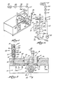
- the improved system of this invention includes a heated reservoir 9 within which solid thermoplastic adhesive is heated and melted, or to which thermoplastic adhesive, which is solid at room temperature, is supplied in the molten state.
- the molten adhesive is supplied from the reservoir to a two-stage gear pump 10 having a first stage 11 and a second stage 12, each stage comprising oppositely rotating and meshed gear pairs 13a and b, and 14a and b respectively.
- the driven gears 13a, 14a of each stage are connected by a common drive shaft 15 to a drive motor 15m, and the idler gears 13b, 14b of each stage are connected by common idler shaft 16.
- the molten hot melt adhesive is introduced, for example at atmospheric pressure into the low pressure side 17 of the first stage pump 11 from the reservoir 9.
- the adhesive is delivered at the outlet side 19 of the first pump 11 at a metered rate, and from there is introduced into inlet side 20 of the second stage pump.
- a gas e.g., air, nitrogen or carbon dioxide, is also introduced into inlet 20 of second stage pump 12, through a gas line 21 from a gas source 22 which may for example be regulated at a pressure in the range of about 1-45 psi.
- Gas inlet line 21 includes a check valve 23 that prevents back flow of molten adhesive from the second stage pump's inlet side 20 through that line 21 toward the gas source 22.
- the gas and molten adhesive are intimately admixed in second stage pump 12, which places them under such pressure that the gas goes into solution with the molten adhesive, thereby providing the molten adhesive/gas solution previously discussed.
- This solution is ejected from the outlet side 24 of second stage pump 12 through a line 25 to a valved adhesive dispenser 26, e.g., a gun or the like.
- a valved adhesive dispenser 26 e.g., a gun or the like.
- a recycle line 27 is provided between the outlet side 24 of second stage pump 12 and the inlet side 17 of first stage pump 11.
- This recycle line includes a relief valve 18 therein, for recycling a part or all of the adhesive/gas solution if the system pressure exceeds the relief setting of valve 18.
- a pressure regulator 28 in the return hose or line 26a from dispenser 26 restricts the recycle flow during cycling of a gun and maintains a fixed back pressure in the system.
- first stage pump 11 meters and delivers molten hot melt adhesive to the inlet side 20 of second stage pump 12. It stabilizes the second stage against viscosity changes and motor speed changes.
- the second stage pump 12 functions as a mixing device for intimately admixing and pressurizing into solution the metered molten hot melt adhesive from first stage pump 11 with the gas infeed from source 22. It has been found that the combination of a first stage metering pump 11 with the second stage mixing pump 12 provides a more uniform adhesive/gas solution output, and that this in turn enhances the reliability and continuity of the adhesive foam output from the valved dispenser 26. In other words, this pump 10 structure improves the mixing of the adhesive and gas and ensures that the foam dispensed will be relatively uniform and virtually free from spitting and sputtering.
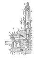
- the adhesive foam pump 10 includes a series of specifically configured plates stacked on top of, and connected to, a manifold block 30.
- the pump 10 includes an inlet end plate 31, a first stage pump plate 32, a center port plate 33, a second stage pump plate 34, and an outlet end plate 35, all of generally the same peripheral configuration and size, and all stacked one on top of the other.
- First stage pump plate 32 defines a cavity 36, which receives the first pair of meshed gears 13a, 13b.
- the second stage or mixing pump plate 34 also defines a cavity 37 which receives the second pair of meshed gears 14a, 14b.
- the second stage pump 12 has a displacement greater than that of the first stage because the gears of the second stage have a greater thickness than the gears of the first stage.
- the volume of gas delivered to the second stage from source 22 fills the additional displacement volume of the second stage, i.e., the volume which is in excess of the volume of hot melt received therein.
- the pump's plates 31-35 are retained in aligned stacked assembled relationship by four bolts (not shown) received therethrough and into threaded bores in the inlet end plate 31, the heads of those bolts being received in seats provided in the end plate 35.
- Throughbolts 40 pass through positioner sleeve 41 in plate bores 42, and are threaded into tapped bores in the manifold block 30 to mount the preassembled plates 31-35 to the manifold block.
- the inlet port plate 31 provides a first stage hot melt inlet port 17 therethrough, that inlet port cooperating with an angled infeed throat 44 defined in the top surface of that port plate.
- Inlet port 17 opens into first stage hot melt inlet zone 45, where the gears come out of mesh.
- the first stage pump plate 32 also includes a first stage outlet zone 19 from which the metered molten hot melt adhesive is directed into intermediate transfer port structure 46 defined in the center port plate 33.
- the intermediate transfer port structure directs metered molten adhesive from outlet side 19 of first stage pump 11 to inlet side 20 of second stage pump 12.
- This intermediate transfer port structure includes first stage hot melt outlet port 19, first to second stage transfer bore 46, and second stage hot melt in port 20, all defined in center port plate 33.
- the metered molten adhesive from first stage pump 11 is thereby introduced into second stage pump 12 from the top side thereof.
- the second stage pump plate 34 further defines the second stage hot melt "in” zone 20 and the second stage “out” zone 24.
- the molten adhesive/gas solution exits via outlet 24 of the second stage pump 12.
- the outlet port 24 cooperates with an outlet throughbore 47 in outlet end plate 35, and that outlet throughbore 47 connects the second stage outlet port 24 with discharge bore 48 in the manifold block 30.
- the discharge bore section 48 in the manifold block is connected via bore 49 and line 25 with the valved adhesive dispensers 26.
- the gas is introduced into inlet side 20 of second stage pump 12 from the bottom side thereof through gas inlet zone 50.
- the check valve 23 is attached to the top side of the reservoir 9 via a conventional threaded fitting 51.
- This fitting is threaded into a threaded section of a counterbored vertical passage 52 which connects with a passage 53 leading to a bore 54 of the reservoir 9 within which the pump 10 is mounted.
- the exterior of the pump 10 is provided with a peripheral groove 55 located at the interface between the plates 34, 35 of the pump.
- This groove 55 communicates with the passage 53 such that gas flowing through the check valve 23 and passages 52, 53 enters the annular groove 55 around the exterior of the pump.
- This groove is sealed by a pair of O-rings 56, 57 located above and beneath the annular groove 55.
- Both of these O-rings contact the exterior surface of the pump and the surfaces of the bore within which the pump is mounted so as to seal the annular groove 55 against the escape of gas from the channel 55.
- a pair of channels or grooves 58 in the top surface of the plate 35 converge toward the pump's axis and interconnect the annular groove 55 with the gas inlet zone 50 of the pump through which gas is introduced into the second stage 12 of the pump. Consequently, gas supplied to the check valve 23 flows via the check valve 23, the passages 52, 53, the annular groove 55, and the channels 58 to the inlet zone 50.
- the check valve 23 is mounted above the level of the bottom surface 60 of the reservoir 9 and above the level of the pump 10. This check valve 23 is operative to prevent the back flow of hot melt adhesive from the pump to the gas flow controls including the gas flow control gauge 61, pressure regulator 62, and a solenoid control valve 63, all of which are in the gas flow control line 21 between the gas source 22 and the check valve 23.
- the check valve 23 is a poppet style of valve comprising a cylinder 64 and a poppet 65.
- the poppet has a poppet head 66 connected by a stem 67 to a stop 68 bolted onto the end of the stem 67.
- the stop 68 is ported as illustrated at 69 so as to permit the flow of gas past the stop.
- Internally of the cylinder 64 of the valve there is a compression spring 70 operative to pull the popped head 66 of the valve into sealing contact with a valve seat 71.
- a compression spring 70 operative to pull the popped head 66 of the valve into sealing contact with a valve seat 71.
- the primary flow path, through the pump, of molten hot melt adhesive and of molten adhesive/gas solution once that solution is admixed in the second stage pump 12 is through bores 48, 49 in the manifold block 30 and hose 25 which in use is connected to a gun.
- a recycle flow path is also provided by which a portion of all of the molten adhesive/gas solution can be recycled back through the pump 10 from the gun, into the first stage pump's inlet zone 45, as illustrated by dotted arrow 75 in Figure 4.
- This dotted path 75 corresponds to the recycle path 27 in Figure 1a).
- recycle passages are provided in center port plate 33, second stage pump plate 34, outlet end plate 35 and manifold block 30.
- these recycle passages include the bore 48, a bore 76 (having relief valve 18 described below therein), a vertical bore 77, a bore 78 through the plates 35, 34, 33 and a lateral passage 79 defined between first stage pump plate 32 and center port plate 33.
- the recycle passages connect with inlet zone 45 of first stage pump 11, from the bottom surface of first stage pump plate 32 at a recycle inlet port 80, for introducing recycle flow of molten adhesive/gas solution from outlet 24 of second stage pump 12 into hot melt inlet zone 45 while molten adhesive (without gas) from inlet 17 is added to the recirculated material in zone 45.
- the reliefvalve indicated at 18 in Figures 1a and 3 may be incorporated as part of pressure regulator valve structure designated generally as 82 in Figure 3 which is received in bore 76 of manifold 30.
- This pressure regulator valve structure 82 includes an outer sleeve 83 which is threaded into bore 76 at 84.
- a relief valve seat 85 is secured at the inner end of sleeve 83.
- Seat 85 has an axial port 86 on which is seated a ball 87.
- Ball 87 is biased against port 86 by a cruciform shaped guide 88 acted upon by a spring 89.
- This spring 89 is a compression spring located between the guide 88 and an internal shoulder 90 of the sleeve 83. Ball 87 is thereby biased toward its seat and bore 86 to form the relief valve 18.
- Sleeve 83 is sealed with respect to bore 76 by 0- rings.
- An internal chamber 91 inside sleeve 83 opens through the sleeve wall via radial ports 92 into communication with recycle bore 77 of the manifold.
- a high pressure condition will exist on bores 48, 26a. This condition will be relieved by the opening of the relief valve 18 so that fluid can flow through bore 86, the interior 91 of sleeve 83, and radial ports 92 to recycle bore 77.
- return line 26a from valved dispenser 26 includes a pressure regulator 28.
- this pressure regulator 28 is also included as part of the circulation valve structure 82.
- an adjustable valve member 93 is axially positionable in the interior of sleeve 83 to the right of ports 92.
- Valve member 93 presents three notches or grooves 94 equally spaced 120° apart at its inner end, each of these grooves 94 having a V-shape as seen in section which forms a valve with a shoulder 95 in sleeve 83.
- Notches 94 are biased to a closed position relative to shoulder 95 by a compression spring 96 engaging one end 97 of the valve member 93.
- This spring 96 is housed within a closed chamber 98 of a pressure adjustment sleeve 99.
- This sleeve 99 is threaded into a counterbored end section 101 of the valve sleeve 83.
- the spring 96 at its end remote from the valve 93 fits over a tubular end section 102 of a piston 103 and is engageable with the end of the piston to bias it against the end 104 of an adjustment screw 105 threaded into the end of the sleeve 99.
- By rotating the screw 105 the position of the piston 103 may be varied to adjust the compression of the spring 96 and thereby the pressure required to effect displacement of the adjustable valve member 93.
- the purpose of the pressure regulator 28 is to maintain a fixed back pressure P, in the recycle hose 26a and consequently in the dispenser gun 26 as well as throughout the system. So long as this back pressure P, remains constant, the flow of adhesive/gas solution from the valve dispenser 26 will remain constant.
- this regulator 28 is operative to maintain the pressure in line 26a constant during flow changes through the regulator 28 as well as during viscosity changes in the adhesive/gas solution flowing through the regulator.
- valve 93 upon start-up of flow of liquid adhesive/gas solution through the line 26a, the valve 93 will be moved rightward from the position illustrated in Figure 3 to the position illustrated in Figure 4. This rightward movement is required so as to enable liquid to flow via the variable restrictor of valve 28 (notch 94 and shoulder 95) into the chamber 120. From the chamber 120 the adhesive/gas solution flows via orifices 121 into the chamber 98 and from the chamber 98 via bore 122 in the valve member 93 to the ports 92 into the vertical bores 77, 78 to the pump.
- valve spool 93 moves from the position illustrated in Figure 3 to the position illustrated in Figure 4 until such time as the force F s of the spring 96 balances the pressure drop occurring at the variable restrictor slot 94 and the fixed restrictor orifices 121 multiplied by the areas over which those pressure drops are operative.
- the pressure P 1 equals the pressure setting of the pressure regulator 28, there is a force balance between the pressure and the spring as follows:
- Viscosity changes are similarly compensated for so as to maintain the pressure P 1 at a fixed value. Viscosity changes occur as a consequence of a varying of the quantity of gas driven into the adhesive/gas solution. As the solution is continuously recycled, as for example occurs when the valve of the dispenser 26 is left closed for a protracted period of time, the level of gas in solution increases and viscosity decreases.
- the pressure regulator 28 compensates for these viscosity changes in the same way that it compensates for flow changes. That is, a lower viscosity has the same effect of lowering the pressure P 2 in chamber 120 and thereby allows the valve to slide to the left, closing the variable restrictor 94 and maintaining P 1 in line 26a at a relatively fixed value.
- the pump 10 and the hot melt adhesive foam system within which it is employed is the subject of the above identified U.S. Patent No. 4,200,207.
- the invention of the application resides in the provision in the system of a pressure regulator 28 and in the configuration of the pressure regulator which enables it to compensate for changes in the flow and viscosity of the adhesive/gas solution in the recycle line 26a to maintain a fixed back pressure in the system.
- molten hot melt adhesive is introduced through port 17 in inlet port plate 31 into first stage pump 11.
- the hot melt adhesive entering the first stage pump may be at ambient pressure.
- the molten adhesive infeed is metered by the first stage pump and transferred from outlet 19 through port 46 to inlet 20 of second stage pump 12.
- the gas from the source 22 is supplied via valve 63, pressure regulator 62 and pressure gauge 61 and valve 23 to the gas inlet zone 50 from which it is introduced into second stage pump 12 just after introduction of the metered molten adhesive from first stage pump 11.
- the pressure at which the gas is introduced will control the density of the foam; pressures in the range of approximately 1-45 psig have already been used.
- the second stage pump 12 mixes the adhesive and gas to provide, under pressure, a molten adhesive/gas solution which is exhausted from the outlet side 24 of the second stage pump, into the discharge bore 48 of manifold block 30.
- relief valve 18 restricts recycle flow of the solution, except for so much as is permitted to flow via pressure regulator 28 to maintain the back pressure in the gun 26 at a preset pressure.
- valved dispenser When the valved dispenser is closed, no adhesive foam is being dispensed, the pressurized adhesive/gas solution continues to recycle through the pressure regulator 28 with any excess flow being recycled through valve 18, sleeve interior 91, recycle bore 77 in the manifold block 30, through recycle bore 78 of the outlet end plate 35, second stage pump plate 34, and center port plate 33, back to inlet zone 45 of the first stage pump 11.
- This hot melt adhesive foam system relative to the system disclosed in U.S. Patent No. 4,200,207, is that it maintains a more even flow of adhesive from the dispenser 26 under all operating conditions of the dispenser than does the system disclosed in U.S. Patent No. 4,200,207. Specifically, it maintains a relatively constant flow rate from the dispenser even though the flow from the gun may be varied for constant long duration flow to short duration intermittent flow or even though the density and viscosity of the solution may be varied.
- solution has been used to describe the molten liquid adhesive/gas dispersion supplied under high pressure which, when dispensed from a dispenser at atmospheric pressure, will provide a foamed adhesive. It is believed this mixture is a true solution in which the gas is molecularly dispersed in the liquid adhesive. It will be appreciated by those skilled in this art however, that the invention is also applicable to a gas homogeneously mixed with a molten liquid adhesive or sealant material whether or not the gas is in fact molecularly dispersed. Further, throughout this specification the phrase “hot melt adhesive” has been used as meaning a solvent-free material which is applied in a molten state.
Landscapes
- Chemical & Material Sciences (AREA)
- Organic Chemistry (AREA)
- Coating Apparatus (AREA)
- Nozzles (AREA)
Applications Claiming Priority (2)
| Application Number | Priority Date | Filing Date | Title |
|---|---|---|---|
| US06/294,191 US4535919A (en) | 1981-08-19 | 1981-08-19 | Hot melt adhesive system |
| US294191 | 1981-08-19 |
Publications (2)
| Publication Number | Publication Date |
|---|---|
| EP0072679A1 EP0072679A1 (en) | 1983-02-23 |
| EP0072679B1 true EP0072679B1 (en) | 1986-04-02 |
Family
ID=23132291
Family Applications (1)
| Application Number | Title | Priority Date | Filing Date |
|---|---|---|---|
| EP82304279A Expired EP0072679B1 (en) | 1981-08-19 | 1982-08-12 | Hot melt adhesive system |
Country Status (5)
| Country | Link |
|---|---|
| US (1) | US4535919A (cg-RX-API-DMAC10.html) |
| EP (1) | EP0072679B1 (cg-RX-API-DMAC10.html) |
| JP (2) | JPS5836677A (cg-RX-API-DMAC10.html) |
| CA (1) | CA1195490A (cg-RX-API-DMAC10.html) |
| DE (1) | DE3270270D1 (cg-RX-API-DMAC10.html) |
Cited By (1)
| Publication number | Priority date | Publication date | Assignee | Title |
|---|---|---|---|---|
| US7311941B2 (en) | 2003-08-11 | 2007-12-25 | The Procter & Gamble Company | Process for improved adhesive application |
Families Citing this family (50)
| Publication number | Priority date | Publication date | Assignee | Title |
|---|---|---|---|---|
| US4779762A (en) * | 1984-05-30 | 1988-10-25 | Nordson Corporation | Method and apparatus for controlling the gas content of dispensed hot melt thermoplastic adhesive foam |
| US4682711A (en) * | 1985-04-08 | 1987-07-28 | Nordson Corporation | Method and apparatus for sealing welded seams of automobiles |
| US5021507A (en) * | 1986-05-05 | 1991-06-04 | National Starch And Chemical Investment Holding Corporation | Arcylic modified reactive urethane hot melt adhesive compositions |
| US4820078A (en) * | 1986-12-29 | 1989-04-11 | Brocious George D | Apparatus for road surface repair with fiber-reinforced asphalt |
| FR2611538B1 (fr) * | 1987-02-27 | 1989-10-27 | Graco France Sa | Installation d'alimentation d'un fluide semi-liquide ou liquide, compressible ou non |
| CA1299032C (en) * | 1988-03-30 | 1992-04-21 | Herman E. Turner, Jr. | Closed cell foam seals for automotive body seams, method and apparatus for making same |
| US5207352A (en) * | 1991-04-19 | 1993-05-04 | Nordson Corporation | Method and apparatus for dispensing high viscosity fluid materials |
| US5319568A (en) * | 1991-07-30 | 1994-06-07 | Jesco Products Co., Inc. | Material dispensing system |
| US5370315A (en) * | 1993-10-15 | 1994-12-06 | Del Gaone; Peter V. | Spray gun for aggregates |
| FR2713959B1 (fr) * | 1993-12-21 | 1996-03-01 | Seva | Installation et procédé de distribution d'un produit fluide avec réservoir et buse. |
| US5618001A (en) * | 1995-03-20 | 1997-04-08 | Binks Manufacturing Company | Spray gun for aggregates |
| EP0844073B1 (en) * | 1995-06-26 | 2002-07-31 | Uponor Innovation Ab | A tubular product and an extrusion apparatus and method |
| DE69905756T2 (de) * | 1998-12-03 | 2004-02-19 | Nordson Corp., Westlake | System zum auftrag von heissschmelzmaterialien mit einer hochtemperaturbeständigen drucksteuerung und einem geheizten, rezirkulierenden verteiler |
| US6533720B1 (en) | 2001-01-17 | 2003-03-18 | Avtar S. Dhindsa | Modular endoscope valve assembly and method |
| US20060009680A1 (en) * | 2001-01-17 | 2006-01-12 | Innon Holdings, Inc. | Endoscope valve assembly and method |
| US6786865B2 (en) | 2001-01-17 | 2004-09-07 | Innon Holdings, Llc | Endoscope valve assembly and method |
| US6986739B2 (en) * | 2001-08-23 | 2006-01-17 | Sciperio, Inc. | Architecture tool and methods of use |
| JP4505851B2 (ja) * | 2003-11-21 | 2010-07-21 | 株式会社サンツール | 気泡入りホットメルト塗布装置 |
| USD519634S1 (en) | 2003-12-08 | 2006-04-25 | Innon Holdings, Llc | Valve assembly |
| EP1744964A4 (en) | 2004-04-22 | 2011-08-31 | Dixie Consumer Products Llc | INSULATED CUP AND INSULATED CONTAINER |
| US7237578B2 (en) * | 2004-07-21 | 2007-07-03 | Nordson Corporation | Rechargeable dispensing head |
| WO2007020940A1 (ja) * | 2005-08-17 | 2007-02-22 | Kosuke Uchiyama | 多段歯車式加工装置 |
| JP5265382B2 (ja) | 2006-01-17 | 2013-08-14 | ノードソン コーポレーション | 熱可塑性材料を溶融及び吐出する装置並びに方法 |
| US7767049B2 (en) | 2006-10-12 | 2010-08-03 | Dixie Consumer Products Llc | Multi-layered container having interrupted corrugated insulating liner |
| JP5024871B2 (ja) * | 2007-07-03 | 2012-09-12 | 旭サナック株式会社 | 高粘度液体塗布装置 |
| US9089869B2 (en) | 2010-02-18 | 2015-07-28 | Adco Products, Llc | Adhesive bead applicator |
| US9566594B2 (en) | 2010-02-18 | 2017-02-14 | Adco Products, Llc | Adhesive applicator |
| WO2011103094A2 (en) * | 2010-02-18 | 2011-08-25 | Adco Products, Inc. | Multi-bead applicator |
| US9174234B2 (en) | 2010-02-18 | 2015-11-03 | Adco Products, Llc | Method of applying a polyurethane adhesive to a substrate |
| US10239087B2 (en) * | 2010-02-18 | 2019-03-26 | Adco Products, Llc | Multi-bead applicator |
| US9186695B2 (en) | 2010-04-01 | 2015-11-17 | B&H Manufacturing Company, Inc. | Extrusion application system |
| US9061316B2 (en) * | 2011-10-28 | 2015-06-23 | Nordson Corporation | Mountable device for dispensing heated adhesive |
| WO2013070720A1 (en) * | 2011-11-07 | 2013-05-16 | Graco Minnesota Inc. | Direct air motor driven pump to dispense valve |
| WO2013070718A1 (en) * | 2011-11-07 | 2013-05-16 | Graco Minnesota Inc. | Automatic gate valve for hot melt adhesive lines |
| US9381536B2 (en) | 2011-12-28 | 2016-07-05 | Adco Products, Llc | Multi-bead applicator |
| US9377114B2 (en) * | 2012-04-25 | 2016-06-28 | Nordson Corporation | Pressure control valve for reactive adhesives |
| US10099242B2 (en) | 2012-09-20 | 2018-10-16 | Nordson Corporation | Adhesive melter having pump mounted into heated housing |
| US9169088B2 (en) | 2012-09-20 | 2015-10-27 | Nordson Corporation | Adhesive dispensing device having optimized cyclonic separator unit |
| US9304028B2 (en) | 2012-09-20 | 2016-04-05 | Nordson Corporation | Adhesive dispensing device having optimized reservoir and capacitive level sensor |
| US9120115B2 (en) | 2012-10-25 | 2015-09-01 | Nordson Corporation | Dispensing systems and methods for monitoring actuation signals for diagnostics |
| US20140117047A1 (en) * | 2012-10-25 | 2014-05-01 | Graco Minnesota Inc. | Pressure relief for adhesive dispensing system |
| US9200741B2 (en) | 2012-10-25 | 2015-12-01 | Nordson Corporation | Adhesive dispensing system and method using smart melt heater control |
| US9243626B2 (en) | 2012-11-19 | 2016-01-26 | Nordson Corporation | Adhesive dispensing system and method including a pump with integrated diagnostics |
| US9574714B2 (en) | 2013-07-29 | 2017-02-21 | Nordson Corporation | Adhesive melter and method having predictive maintenance for exhaust air filter |
| JP6623741B2 (ja) * | 2015-12-18 | 2019-12-25 | 株式会社スリーボンド | 機械式発泡装置および機械式発泡方法 |
| US10722909B1 (en) | 2018-11-01 | 2020-07-28 | Paul Charles Waelder | System and method of delivering reactive fluids to an applicator |
| WO2020190727A1 (en) * | 2019-03-15 | 2020-09-24 | Nordson Corporation | Hot melt adhesive foam dispensing system |
| JP7593741B2 (ja) * | 2020-03-26 | 2024-12-03 | ノードソン コーポレーション | ノズル、接着剤塗布ヘッド、接着剤塗布装置及びおむつ製造方法 |
| EP4108413B1 (en) * | 2021-06-25 | 2023-07-26 | Sunstar Engineering Inc. | Method for adjusting pressure of mixture of gas and paste material discharged from dispenser |
| USD1097668S1 (en) * | 2023-05-10 | 2025-10-14 | Lineng (Foshan City) Plastic Products Co., Ltd | Automatic liquid dispensing machine |
Family Cites Families (9)
| Publication number | Priority date | Publication date | Assignee | Title |
|---|---|---|---|---|
| US2011333A (en) * | 1931-09-21 | 1935-08-13 | James P Clifton | Valve |
| US2616445A (en) * | 1945-11-28 | 1952-11-04 | Gaddoni Louis | Gasoline economizer |
| DE2254033A1 (de) * | 1972-11-04 | 1974-05-16 | Paal Hans | Vorrichtung zum punktweisen auftragen eines klebstoffes |
| US3806037A (en) * | 1972-12-01 | 1974-04-23 | Hanson Equipment Co | Selective fluid discharge system and control valve means therefor |
| CH623352A5 (en) * | 1976-08-02 | 1981-05-29 | Nordson Corp | Process for bonding two substrates together with the aid of a heat-activated thermoplastic adhesive and apparatus for making use of this process |
| US4059714A (en) * | 1976-08-02 | 1977-11-22 | Nordson Corporation | Hot melt thermoplastic adhesive foam system |
| US4059466A (en) * | 1976-08-02 | 1977-11-22 | Nordson Corporation | Hot melt thermoplastic adhesive foam system |
| US4200207A (en) * | 1978-02-01 | 1980-04-29 | Nordson Corporation | Hot melt adhesive foam pump system |
| US4237922A (en) * | 1978-09-25 | 1980-12-09 | Snap-Tite, Inc. | In-line flow control valve |
-
1981
- 1981-08-19 US US06/294,191 patent/US4535919A/en not_active Expired - Lifetime
-
1982
- 1982-08-12 EP EP82304279A patent/EP0072679B1/en not_active Expired
- 1982-08-12 DE DE8282304279T patent/DE3270270D1/de not_active Expired
- 1982-08-19 JP JP57142732A patent/JPS5836677A/ja active Pending
- 1982-08-19 CA CA000409769A patent/CA1195490A/en not_active Expired
-
1991
- 1991-02-18 JP JP1991006421U patent/JPH0728940Y2/ja not_active Expired - Lifetime
Cited By (1)
| Publication number | Priority date | Publication date | Assignee | Title |
|---|---|---|---|---|
| US7311941B2 (en) | 2003-08-11 | 2007-12-25 | The Procter & Gamble Company | Process for improved adhesive application |
Also Published As
| Publication number | Publication date |
|---|---|
| US4535919A (en) | 1985-08-20 |
| JPH0499271U (cg-RX-API-DMAC10.html) | 1992-08-27 |
| JPS5836677A (ja) | 1983-03-03 |
| DE3270270D1 (en) | 1986-05-07 |
| EP0072679A1 (en) | 1983-02-23 |
| JPH0728940Y2 (ja) | 1995-07-05 |
| CA1195490A (en) | 1985-10-22 |
Similar Documents
| Publication | Publication Date | Title |
|---|---|---|
| EP0072679B1 (en) | Hot melt adhesive system | |
| US4200207A (en) | Hot melt adhesive foam pump system | |
| EP0509323B1 (en) | Apparatus for dispensing high viscosity fluid materials | |
| US4679710A (en) | Hot melt foam adhesive system | |
| US4396529A (en) | Method and apparatus for producing a foam from a viscous liquid | |
| CA1085098A (en) | Hot melt thermoplastic adhesive foam system | |
| US4632314A (en) | Adhesive foam generating nozzle | |
| AU668227B2 (en) | Method and apparatus for compensating for changes in viscosity in a two-component dispensing system | |
| CA2197891C (en) | Method and apparatus for producing closed cell foam | |
| GB1562562A (en) | Hot melt thermoplastic adhesive foam system | |
| EP1000723B1 (en) | Apparatus for foaming a viscous material | |
| CA1102227A (en) | Hot melt thermoplastic adhesive foam system | |
| CA1147236A (en) | Control apparatus for pressurized gas/liquid systems | |
| US5372283A (en) | Two-component dispensing system | |
| US6793098B2 (en) | System and apparatus for foam dispensing with adjustable orifice flow regulating device and method of using same | |
| JPH07185397A (ja) | 遮断時滴下防止機能を伴う液体ディスペンサ | |
| CA2092427A1 (en) | Chemical flow stream separator | |
| US4003501A (en) | Fluid impingement mixing apparatus | |
| US4938381A (en) | Method and apparatus for dispensing a foam product | |
| US20050094482A1 (en) | Method and apparatus for producing closed cell foam | |
| CA1200466A (en) | Pressure regulator | |
| US4601427A (en) | Adhesive dispensing nozzle | |
| US4291991A (en) | Apparatus for the preparation of a reaction mixture from fluid components | |
| US20020132859A1 (en) | Method and apparatus for mixing a high-viscosity material into a gas | |
| CA1100450A (en) | Method and apparatus for producing a foam from a viscous liquid |
Legal Events
| Date | Code | Title | Description |
|---|---|---|---|
| PUAI | Public reference made under article 153(3) epc to a published international application that has entered the european phase |
Free format text: ORIGINAL CODE: 0009012 |
|
| AK | Designated contracting states |
Designated state(s): BE CH DE FR GB IT LI NL |
|
| 17P | Request for examination filed |
Effective date: 19830801 |
|
| GRAA | (expected) grant |
Free format text: ORIGINAL CODE: 0009210 |
|
| AK | Designated contracting states |
Kind code of ref document: B1 Designated state(s): BE CH DE FR GB IT LI NL |
|
| REF | Corresponds to: |
Ref document number: 3270270 Country of ref document: DE Date of ref document: 19860507 |
|
| ITF | It: translation for a ep patent filed | ||
| ET | Fr: translation filed | ||
| PLBE | No opposition filed within time limit |
Free format text: ORIGINAL CODE: 0009261 |
|
| STAA | Information on the status of an ep patent application or granted ep patent |
Free format text: STATUS: NO OPPOSITION FILED WITHIN TIME LIMIT |
|
| 26N | No opposition filed | ||
| PGFP | Annual fee paid to national office [announced via postgrant information from national office to epo] |
Ref country code: FR Payment date: 19930713 Year of fee payment: 12 |
|
| PGFP | Annual fee paid to national office [announced via postgrant information from national office to epo] |
Ref country code: CH Payment date: 19930714 Year of fee payment: 12 |
|
| PGFP | Annual fee paid to national office [announced via postgrant information from national office to epo] |
Ref country code: GB Payment date: 19930715 Year of fee payment: 12 |
|
| PGFP | Annual fee paid to national office [announced via postgrant information from national office to epo] |
Ref country code: BE Payment date: 19930716 Year of fee payment: 12 |
|
| PGFP | Annual fee paid to national office [announced via postgrant information from national office to epo] |
Ref country code: DE Payment date: 19930721 Year of fee payment: 12 |
|
| ITTA | It: last paid annual fee | ||
| PGFP | Annual fee paid to national office [announced via postgrant information from national office to epo] |
Ref country code: NL Payment date: 19930831 Year of fee payment: 12 |
|
| PG25 | Lapsed in a contracting state [announced via postgrant information from national office to epo] |
Ref country code: GB Effective date: 19940812 |
|
| PG25 | Lapsed in a contracting state [announced via postgrant information from national office to epo] |
Ref country code: LI Effective date: 19940831 Ref country code: CH Effective date: 19940831 Ref country code: BE Effective date: 19940831 |
|
| BERE | Be: lapsed |
Owner name: NORDSON CORP. Effective date: 19940831 |
|
| PG25 | Lapsed in a contracting state [announced via postgrant information from national office to epo] |
Ref country code: NL Effective date: 19950301 |
|
| GBPC | Gb: european patent ceased through non-payment of renewal fee |
Effective date: 19940812 |
|
| NLV4 | Nl: lapsed or anulled due to non-payment of the annual fee | ||
| PG25 | Lapsed in a contracting state [announced via postgrant information from national office to epo] |
Ref country code: FR Effective date: 19950428 |
|
| REG | Reference to a national code |
Ref country code: CH Ref legal event code: PL |
|
| PG25 | Lapsed in a contracting state [announced via postgrant information from national office to epo] |
Ref country code: DE Effective date: 19950503 |
|
| REG | Reference to a national code |
Ref country code: FR Ref legal event code: ST |