EP0072402A2 - Method of and device for the elimination or reduction of the edge mismatch in joining pipes together end-to-end by welding - Google Patents
Method of and device for the elimination or reduction of the edge mismatch in joining pipes together end-to-end by welding Download PDFInfo
- Publication number
- EP0072402A2 EP0072402A2 EP82105445A EP82105445A EP0072402A2 EP 0072402 A2 EP0072402 A2 EP 0072402A2 EP 82105445 A EP82105445 A EP 82105445A EP 82105445 A EP82105445 A EP 82105445A EP 0072402 A2 EP0072402 A2 EP 0072402A2
- Authority
- EP
- European Patent Office
- Prior art keywords
- pipe
- pipe part
- hollow cylinder
- mandrel
- recess
- Prior art date
- Legal status (The legal status is an assumption and is not a legal conclusion. Google has not performed a legal analysis and makes no representation as to the accuracy of the status listed.)
- Granted
Links
Images
Classifications
-
- B—PERFORMING OPERATIONS; TRANSPORTING
- B23—MACHINE TOOLS; METAL-WORKING NOT OTHERWISE PROVIDED FOR
- B23K—SOLDERING OR UNSOLDERING; WELDING; CLADDING OR PLATING BY SOLDERING OR WELDING; CUTTING BY APPLYING HEAT LOCALLY, e.g. FLAME CUTTING; WORKING BY LASER BEAM
- B23K33/00—Specially-profiled edge portions of workpieces for making soldering or welding connections; Filling the seams formed thereby
- B23K33/004—Filling of continuous seams
- B23K33/006—Filling of continuous seams for cylindrical workpieces
-
- B—PERFORMING OPERATIONS; TRANSPORTING
- B29—WORKING OF PLASTICS; WORKING OF SUBSTANCES IN A PLASTIC STATE IN GENERAL
- B29C—SHAPING OR JOINING OF PLASTICS; SHAPING OF MATERIAL IN A PLASTIC STATE, NOT OTHERWISE PROVIDED FOR; AFTER-TREATMENT OF THE SHAPED PRODUCTS, e.g. REPAIRING
- B29C66/00—General aspects of processes or apparatus for joining preformed parts
- B29C66/01—General aspects dealing with the joint area or with the area to be joined
- B29C66/02—Preparation of the material, in the area to be joined, prior to joining or welding
- B29C66/022—Mechanical pre-treatments, e.g. reshaping
Definitions
- the invention relates to a method and a device for eliminating or reducing the edge misalignment when connecting pipe bodies or pipe parts over mutually opposite ends with the aid of a weld seam.
- deviations in shape which may be caused by them, for example, or may be increased in addition to the deviations in shape as a result of the tolerances customary in the trade in that the pipe part has been subjected to a compression molding process in its longitudinal direction from the ends for deformation purposes.
- Such deviations require an edge offset and an elaborate mechanical processing at the ends of the spool to be produced. in order to correct the discrepancies caused by the edge offset.
- the invention essentially aims to eliminate the aforementioned disadvantages.
- the method for this according to the invention essentially avoids the disadvantageous edge offset in that, when pressure is exerted on the tubular body or the pipeline part in the longitudinal direction, one end of the tubular body or the pipeline part is pushed onto a calibration mandrel and at the same time in a hollow cylinder surrounding the calibrating mandrel with a the inner diameter corresponding to the outer diameter of the pipe body or the pipe part and pressed with the end dipping into the hollow cylinder under pressure to bear against the bottom of the hollow cylinder in order to deform the end face edge of the pipe body or the pipe part in accordance with a desired or required shape of the Weld is brought.
- the pipe part can be brought to a temperature suitable for the material, taking into account the deformation work to be performed.
- the inventive method ensures that inaccuracies, in particular out-of-roundness of the tube, for. B. due to the commercial tolerances, serf, so that between the parts to be connected only a small edge offset can occur, which is required above all in power plant construction.
- Another advantage of the pressed welding edges - is that gradually thickening occurs on these pipe ends treated or prepared in this way, which allows any mechanical processing after the welding process, without causing the risk of the wall thickness being less than that. This fact helps with the ultrasonic testing for longitudinal and Cross errors to favorable results.
- the method can expediently be combined or combined with a compression upsetting of the pipeline part or a straight pipeline part by applying pressure in the longitudinal direction of the pipeline part.
- Compression upsetting can be carried out, for example, to create bends. For elbows to form in a pipe or in a pipe part by thickening.
- a device for carrying out the method is characterized in that in a press or pressure ram which is intended to act on an end face of the tubular body or the pipeline part in its longitudinal direction or longitudinal axis in a recess on the side facing the workpiece with a through the Outside diameter of the pipe part, the inside diameter for receiving the end of the pipe part is provided with a calibration mandrel of an outside diameter corresponding to the inside diameter of the pipe part for engagement in the end of the pipe body or the end of the pipe part, and that the bottom ring surface between the mandrel and the hollow cylinder or the recess wall has a shape corresponding to a desired weld.
- the calibration dome can expediently protrude from the recess surrounding it and from the end face of the press and pressure stamp. This facilitates the plugging of the pipe part on the calibration dome and the introduction of the pipe part into the recess of the pressure stamp.
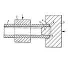
- the drawing schematically illustrates an embodiment of the device according to the invention for carrying out the method according to the invention.
- the part of the pipeline which is to be subjected, for example, to deformation by compression molding in the longitudinal direction, is designated by 1. It is clamped between hydraulically operated jaws 2. In the longitudinal direction of the clamped pipe part 1, the pressure or press ram 3 is provided.
- a recess 4 is provided in the form of a hollow cylinder which is axially identical to the press die and the pipeline part and which has an inside diameter which is the same as the outside diameter of the workpiece 1 or approximately the same while leaving some play.
- the calibration mandrel 5 is located in the recess or the hollow cylinder on the press ram, the outside diameter of which is determined by the inside diameter of the pipe part 1. The mandrel protrudes from the punch 3.
- the bottom 6 of the recess 4 has a shape due to the weld seam to be drawn, in the present case the shape of a half tulip stem for a tulip weld seam.
- Both mutually facing pipe ends at a connection point can be subjected to the treatment according to the invention.
- the workpiece is compressed in the ! Heat, ie when the workpiece is heated to the deformation temperature.
Landscapes
- Engineering & Computer Science (AREA)
- Mechanical Engineering (AREA)
- Butt Welding And Welding Of Specific Article (AREA)
- Pressure Welding/Diffusion-Bonding (AREA)
- Forging (AREA)
- Rigid Containers With Two Or More Constituent Elements (AREA)
- Shaping Of Tube Ends By Bending Or Straightening (AREA)
Abstract
Die Erfindung hat die Behandlung der Enden von Rohrleitungsteilen zum Gegenstand, die über den Stoß an einander zugewandten Stirnflächen mit Hilfe einer Schweißnaht miteinander verbunden werden. Durch die Erfindung soll hierbei eine Schweißkantenversetzung der einander zugewandten Enden behoben bzw. gemindert werden. Es ist ein Preßstempel vorgesehen, der in Achsrichtung des Rohrleitungsteils gegen dessen Stirnfläche zur Wirkung gebracht wird, und dabei einen Kalibrierdorn, der einen dem Innendurchmesser des Rohrleitungsendes gleichen Außendurchmesser hat, in das Rohrleitungsende einschiebt und hierbei das Ende des Rohrleitungsteils mit einem in dem Stempel vorgesehenen Hohlzylinder aufnimmt, der den Kalibrierdorn umgibt und einen dem Außendurchmesser des Endes des Rohrleitungsteils entsprechenden Innendurchmesser aufweist. Der Bodenring zwischen dem Kalibrierdorn und dem Hohlzylinder ist einer gewünschten Form der zu schaffenden Schweißnaht entsprechend geformt und bildet dementsprechend das Stirnende des Endes des Rohrleitungsteils aus. Es kann in einer für das Material des Rohrleitungsendes geeigneten Hitze gearbeitet werden.
Description
Die Erfindung bezieht sich auf ein Verfahren und eine Vorrichtung zum Beheben bzw. Verringern des Kantenversatzes bei der Verbindung von Rohrkörpern bzw. Rohrleitungsteilen über sich gegenüberstehende Stirnenden mit Hilfe einer Schweißnaht.The invention relates to a method and a device for eliminating or reducing the edge misalignment when connecting pipe bodies or pipe parts over mutually opposite ends with the aid of a weld seam.
Insbesondere im Rohrleitungsbau besteht vielfach die Notwendigkeit, Rohrleitungsteile miteinander zu verbinden. Dies wird im allgemeinen in der Weise durchge-führt, daß die miteinander zu verbindenden Rohre gleicher Dimensionierung Kopf an Kopf, d. h. mit den Stirnenden bei gleichem Durchmesser und Wanddicken aneinander gesetzt werden und in der Stoßfuqe eine verbindende Schweißnaht gezogen wird. Hierfür können die zum gegenseitiqen Gegenüberstehen kommenden Endstirnränder der Rohrteile eine durch die zu ziehende Schweißnaht, z- B. eine V-Naht, bedingte Form aufweisen. Die Rohrleitungsteile besitzen in der Regel Unrundheiten aufqrund der handelsüblichen Toleranzen. Auch können Formabweichungen vorliegen, die beispielsweise ihre Ursache darin haben können bzw. zusätzlich zu den Formabweichungen infolge der handelsüblichen Toleranzen dadurch gesteigert sein können, daß der Rohrleitungsteil einem Stauchpressvorgang in seiner Längsrichtung von den Stirnenden aus zu Verformungszwecken unterworfen worden ist. Solche Abweichungen bedingen einen Kantenversatz und eien aufwendige mechanische Bearbeitung an den Enden des zu fertigenden Spools. um die durch den Kantenversatz gegebenen Mißhelligkeiten zu beheben.In pipeline construction in particular, there is often a need to connect pipeline parts to one another. This will results in e-generally in the manner by g that the same pipes to be connected sizing head to head, that is, with the front ends of the same diameter and wall thickness are set against each other and is drawn a connecting weld in the Stoßfuqe. For this purpose, the end face edges of the tube parts that come to face each other can have a shape due to the weld seam to be drawn, for example a V-seam. The pipe parts generally have out-of-roundness due to the usual tolerances. There may also be deviations in shape, which may be caused by them, for example, or may be increased in addition to the deviations in shape as a result of the tolerances customary in the trade in that the pipe part has been subjected to a compression molding process in its longitudinal direction from the ends for deformation purposes. Such deviations require an edge offset and an elaborate mechanical processing at the ends of the spool to be produced. in order to correct the discrepancies caused by the edge offset.
Die Erfindung erstrebt im wesentlichen die Beseitigung der vorgenannten Nachteile.The invention essentially aims to eliminate the aforementioned disadvantages.
Das Verfahren hierzu nach der Erfindung vermeidet im wesentlichen den nachteiligen Kantenversatz dadurch, daß unter Druckausübung auf den Rohrkörper bzw. den Rohrleitungsteil in dessen Längsrichtung das eine Ende des Rohrkörpers bzw. des Rohrleitungsteils auf einen Kalibrierdorn aufgeschoben und gleichzeitig in einen den Kalibrierdorn umgebenden Hohlzylinder mit einem dem Außendurchmesser des Rohrkörpers bzw. des Rohrleitungsteils entsprechenden bzw. gleichen Innendurchmesser gedrückt und mit dem in den Hohlzylinder eintauchenden Ende unter Druck zur Anlage gegen den Boden des Hohl- zylinders zwecks Verformung des Endstirnrandes des Rohrkörpers bzw. des Rohrleitungsteils entsprechend einer erwünschten oder geforderten Form der Schweißnaht gebracht wird. Der Rohrleitungsteil kann mit Rücksicht auf die zu verrichtende Verformungsarbeit auf eine für das Material geeianete Temperatur qebracht werden.The method for this according to the invention essentially avoids the disadvantageous edge offset in that, when pressure is exerted on the tubular body or the pipeline part in the longitudinal direction, one end of the tubular body or the pipeline part is pushed onto a calibration mandrel and at the same time in a hollow cylinder surrounding the calibrating mandrel with a the inner diameter corresponding to the outer diameter of the pipe body or the pipe part and pressed with the end dipping into the hollow cylinder under pressure to bear against the bottom of the hollow cylinder in order to deform the end face edge of the pipe body or the pipe part in accordance with a desired or required shape of the Weld is brought. The pipe part can be brought to a temperature suitable for the material, taking into account the deformation work to be performed.
Durch das erfindungsgemäße Verfahren ist erreicht, daß Ungenauigkeiten, insbesondere Unrundheiten des Rohres, z. B. aufgrund der handelsüblichen Toleranzen, ausgeschaltet werderf, so daß zwischen den zu verbindenden Teilen nur ein geringer Kantenversatz auftreten kann, was vor allen Dingen im Kraftwerksbau gefordert wird.The inventive method ensures that inaccuracies, in particular out-of-roundness of the tube, for. B. due to the commercial tolerances, werderf, so that between the parts to be connected only a small edge offset can occur, which is required above all in power plant construction.
Ein weiterer Vorteil der angepreßten Schweißkanten - besteht auch darin, daß an diesen so behandelten bzw. vorbereiteten Rohrenden allmählich verlaufende Verdikkungen entstehen, die nach dem Schweißvorgang jede mechanische Bearbeitung zulassen, ohne die Gefahr einer Wanddickenunterschreitung hervorzurufen. Dieser Umstand verhilft bei der Ultraschallprüfung auf Längs- und Querfehler zu günstigen Ergebnissen.Another advantage of the pressed welding edges - is that gradually thickening occurs on these pipe ends treated or prepared in this way, which allows any mechanical processing after the welding process, without causing the risk of the wall thickness being less than that. This fact helps with the ultrasonic testing for longitudinal and Cross errors to favorable results.
Zweckmässiq kann das Verfahren mit einer Druckstauchverformung des Rohrleitungsteils bzw. eines geraden Rohrleitungsteils durch Druckausübung in der Längsrichtung des Rohrleitungsteils verbunden bzw. kombiniert werden. Eine Druckstauchverformung kann beispielsweise zur Schaffung von Biegestellen.für eine Krümmerbildung in einem Rohr bzw. in einem Rohrleitungsteil durch Verdickungen erfolgen.The method can expediently be combined or combined with a compression upsetting of the pipeline part or a straight pipeline part by applying pressure in the longitudinal direction of the pipeline part. Compression upsetting can be carried out, for example, to create bends. For elbows to form in a pipe or in a pipe part by thickening.
Eine Vorrichtung nach der Erfindung zur Durchführung des Verfahrens kennzeichnet sich dadurch, daß in einem zur Wirkung auf ein Stirnende des Rohrkörpers bzw. des Rohrleitungsteils in dessenLängsrichtung oder Längsachse bestimmten Preß- bzw. Druckstempel in einer Ausnehmuhg auf der dem Werkstück zugewandten Seite mit einem durch den Außendurchmesser des Rohrleitungsteils bestimmten Innendurchmesser zur Aufnahme des Endes des Rohrleitungsteils ein Kalibrierdorn von einem dem Innendurchmesser des Rohrleitungsteils entsprechenden Außendurchmesser für den Eingriff in das Rohrkörperende bzw. das Ende des Rohrleitungsteils vorqesehen ist, und daß die Bodenringfläche zwischen dem Dorn und dem Hohlzylinder bzw. der Ausnehmungswand eine einer gewünschten Schweißnaht entsprechende Form aufweist.A device according to the invention for carrying out the method is characterized in that in a press or pressure ram which is intended to act on an end face of the tubular body or the pipeline part in its longitudinal direction or longitudinal axis in a recess on the side facing the workpiece with a through the Outside diameter of the pipe part, the inside diameter for receiving the end of the pipe part is provided with a calibration mandrel of an outside diameter corresponding to the inside diameter of the pipe part for engagement in the end of the pipe body or the end of the pipe part, and that the bottom ring surface between the mandrel and the hollow cylinder or the recess wall has a shape corresponding to a desired weld.
Der Kalibrierdom kann zweckmässig aus der ihn umgebenden Ausnehmung und von der Stirnfläche des Preß-und Druckstempels vorstehen. Dies erleichtert das Aufstecken des Rohrleitungsteils auf den Kalibrierdom und die Einführung des Rohrleitunqsteils in die Ausnehmunq des Druckstempels.The calibration dome can expediently protrude from the recess surrounding it and from the end face of the press and pressure stamp. This facilitates the plugging of the pipe part on the calibration dome and the introduction of the pipe part into the recess of the pressure stamp.
Die Zeichnung veranschaulicht schematisch ein Ausführungsbeispiel der erfindungsgemäßen Vorrichtung zur Durchführung des Verfahrens nach der Erfindung.The drawing schematically illustrates an embodiment of the device according to the invention for carrying out the method according to the invention.
Die Zeichnung beschränkt sich auf die zum Verständnis der Erfindung notwendigen Teile.The drawing is limited to the parts necessary for understanding the invention.
Der Rohrleitungsteil, der beispielsweise einer Verformung durch Stauchpressen in der Längsrichtung unterworfen werden soll, ist mit 1 bezeichnet. Er wird zwischen hydraulisch zu betätigenden Spannbacken 2 eingespannt. In der Längsrichtung des eingespannten Rohrteils 1 verschiebbar ist der Druck- bzw. Preßstempel 3 vorgesehen.The part of the pipeline which is to be subjected, for example, to deformation by compression molding in the longitudinal direction, is designated by 1. It is clamped between hydraulically operated jaws 2. In the longitudinal direction of the clamped pipe part 1, the pressure or
In der dem Werkstück 1 zuqewandten Seite des Preßstempels 3 ist eine Ausnehmung 4 in Form eines dem Preßstempel und dem Rohrleitungsteil achsgleichen Hohlzylinders vorgesehen, der einen dem Außendurchmesser des Werkstückes 1 gleichen bzw. unter Belassung von etwas Spiel etwa gleichen Innendurchmesser aufweist. In der Ausnehmung bzw. dem Hohlzylinder befindet sich am Preßstempel der Kalibrierdorn 5, dessen Außendurchmesser durch den Innendurchmesser des Rohrleitungsteils 1 bestimmt ist. Der Dorn steht vom Preßstempel 3 vor.In the side of the
Der Boden 6 der Ausnehmung 4 hat eine durch die zu ziehende Schweißnaht bedingte Form, vorliegendenfalls für eine Tulpenschweißnaht die Form eines halben Tulpenkelches.The
Beide einander zugewandte Rohrenden an einer Verbindungsstelle können der erfindungsgemäßen Behandlung unterworfen werden.Both mutually facing pipe ends at a connection point can be subjected to the treatment according to the invention.
Das Stauchpressen des Werkstücks erfolgt in der ! Wärme, d. h. bei auf Verformungstemperatur erhitztem Werkstück.The workpiece is compressed in the ! Heat, ie when the workpiece is heated to the deformation temperature.
Claims (4)
Priority Applications (1)
| Application Number | Priority Date | Filing Date | Title |
|---|---|---|---|
| AT82105445T ATE18644T1 (en) | 1981-06-27 | 1982-06-22 | METHOD AND DEVICE FOR FIXING REDUCING THE EDGE OFFSET WHEN JOINING PIPE BODY OVER OPPOSING END END BY WELDING. |
Applications Claiming Priority (2)
| Application Number | Priority Date | Filing Date | Title |
|---|---|---|---|
| DE3125435A DE3125435C1 (en) | 1981-06-27 | 1981-06-27 | Method and device for eliminating or reducing the edge misalignment when connecting tubular bodies to opposite ends by welding |
| DE3125435 | 1981-06-27 |
Publications (3)
| Publication Number | Publication Date |
|---|---|
| EP0072402A2 true EP0072402A2 (en) | 1983-02-23 |
| EP0072402A3 EP0072402A3 (en) | 1983-09-21 |
| EP0072402B1 EP0072402B1 (en) | 1986-03-19 |
Family
ID=6135577
Family Applications (1)
| Application Number | Title | Priority Date | Filing Date |
|---|---|---|---|
| EP82105445A Expired EP0072402B1 (en) | 1981-06-27 | 1982-06-22 | Method of and device for the elimination or reduction of the edge mismatch in joining pipes together end-to-end by welding |
Country Status (5)
| Country | Link |
|---|---|
| EP (1) | EP0072402B1 (en) |
| JP (2) | JPS5850132A (en) |
| AT (1) | ATE18644T1 (en) |
| DE (1) | DE3125435C1 (en) |
| ZA (1) | ZA824591B (en) |
Family Cites Families (4)
| Publication number | Priority date | Publication date | Assignee | Title |
|---|---|---|---|---|
| FR695339A (en) * | 1930-05-08 | 1930-12-13 | Welding assembly process for metal pipes | |
| GB1201693A (en) * | 1967-09-01 | 1970-08-12 | Kocks Wermelskirchen G M B H | Apparatus for calibrating pipes |
| US3594894A (en) * | 1968-11-20 | 1971-07-27 | Gen Fire Extinguisher Corp | Method of forming cartridges |
| US3752348A (en) * | 1971-08-30 | 1973-08-14 | Ford Motor Co | Motor vehicle electrically heated windshield and backlight system |
-
1981
- 1981-06-27 DE DE3125435A patent/DE3125435C1/en not_active Expired
-
1982
- 1982-06-22 EP EP82105445A patent/EP0072402B1/en not_active Expired
- 1982-06-22 AT AT82105445T patent/ATE18644T1/en not_active IP Right Cessation
- 1982-06-28 ZA ZA824591A patent/ZA824591B/en unknown
- 1982-06-28 JP JP57110048A patent/JPS5850132A/en active Pending
-
1984
- 1984-09-28 JP JP1984145808U patent/JPS60103521U/en active Pending
Also Published As
| Publication number | Publication date |
|---|---|
| EP0072402A3 (en) | 1983-09-21 |
| JPS60103521U (en) | 1985-07-15 |
| ZA824591B (en) | 1983-10-26 |
| EP0072402B1 (en) | 1986-03-19 |
| ATE18644T1 (en) | 1986-04-15 |
| DE3125435C1 (en) | 1983-05-19 |
| JPS5850132A (en) | 1983-03-24 |
Similar Documents
| Publication | Publication Date | Title |
|---|---|---|
| EP0523215B1 (en) | Process for the hydrostatic shaping of hollow bodies of cold-workable metal and device for implementing it | |
| DE2657269B2 (en) | Process for the production of steel pipes | |
| DE3226868C2 (en) | ||
| DE4337517A1 (en) | Process for the hydroforming of hollow stepped shafts made of cold-formable metal | |
| DE19520099C2 (en) | Pipe connection and process for its manufacture | |
| DE2818671A1 (en) | METHOD FOR RELAXING A MECHANICALLY ROLLED TUBE | |
| DE4322711C2 (en) | Method of making a pipe bend | |
| EP2205371B1 (en) | Method for producing pipe-in-pipe systems | |
| DE69322965T2 (en) | METHOD FOR PRODUCING TUBULAR ELEMENTS WITH INTEGRAL EXTERNAL PROJECTS | |
| DE19820124A1 (en) | Steering rod tube production | |
| DE19757946C2 (en) | pipe connection | |
| EP0072402A2 (en) | Method of and device for the elimination or reduction of the edge mismatch in joining pipes together end-to-end by welding | |
| DE3021940C2 (en) | Method and system for the production of pipes on pipe push bench systems | |
| DE532919C (en) | Manufacture of pipes with inwardly reinforced ends by upsetting | |
| DE3247200A1 (en) | Process and bending press for the bending of a straight pipe to form a pipe bend with connected straight legs | |
| DE102011107450A1 (en) | Device for reshaping tube, comprises main clamping jaw arrangement for clamping primary portion of tube, and symmetric expansion tool for symmetric expansion of the end portions of tube | |
| EP0441174A2 (en) | Method and form tool for heading a nipple | |
| DE906164C (en) | Non-releasable connection between a pipe and another body and method of making the connection | |
| EP0070406A2 (en) | Method of producing a pipework duct having at least one elbow between two straight lengths of pipe | |
| DE1261102B (en) | Method and device for the manufacture of pipe bends with a cross section that tapers evenly from one end to the other | |
| DE10061635A1 (en) | Forming and joining process of at least two components and device | |
| DE3633959C1 (en) | Method for the production of a tube end with a connection | |
| DE19854044C1 (en) | Method of connecting pipes | |
| DE1627788B1 (en) | METHOD OF MANUFACTURING A CYLINDRICAL ROD OF STEEL WITH A CLADDED TUBULAR SHEATH OF STEEL OF OTHER CHEMICAL COMPOSITION | |
| DE4329540C1 (en) | Apparatus for calibrating bent pipe sections of essentially circular cross-section |
Legal Events
| Date | Code | Title | Description |
|---|---|---|---|
| PUAI | Public reference made under article 153(3) epc to a published international application that has entered the european phase |
Free format text: ORIGINAL CODE: 0009012 |
|
| AK | Designated contracting states |
Designated state(s): AT BE CH FR GB IT LI LU NL SE |
|
| 17P | Request for examination filed |
Effective date: 19830121 |
|
| PUAL | Search report despatched |
Free format text: ORIGINAL CODE: 0009013 |
|
| AK | Designated contracting states |
Designated state(s): AT BE CH FR GB IT LI LU NL SE |
|
| RAP1 | Party data changed (applicant data changed or rights of an application transferred) |
Owner name: EMIL WOLFF MASCHINENFABRIK UND EISENGIESSEREI GMBH |
|
| GRAA | (expected) grant |
Free format text: ORIGINAL CODE: 0009210 |
|
| AK | Designated contracting states |
Kind code of ref document: B1 Designated state(s): AT BE CH FR GB IT LI LU NL SE |
|
| PG25 | Lapsed in a contracting state [announced via postgrant information from national office to epo] |
Ref country code: NL Effective date: 19860319 Ref country code: IT Free format text: LAPSE BECAUSE OF FAILURE TO SUBMIT A TRANSLATION OF THE DESCRIPTION OR TO PAY THE FEE WITHIN THE PRESCRIBED TIME-LIMIT;WARNING: LAPSES OF ITALIAN PATENTS WITH EFFECTIVE DATE BEFORE 2007 MAY HAVE OCCURRED AT ANY TIME BEFORE 2007. THE CORRECT EFFECTIVE DATE MAY BE DIFFERENT FROM THE ONE RECORDED. Effective date: 19860319 Ref country code: FR Free format text: THE PATENT HAS BEEN ANNULLED BY A DECISION OF A NATIONAL AUTHORITY Effective date: 19860319 Ref country code: BE Effective date: 19860319 |
|
| REF | Corresponds to: |
Ref document number: 18644 Country of ref document: AT Date of ref document: 19860415 Kind code of ref document: T |
|
| PG25 | Lapsed in a contracting state [announced via postgrant information from national office to epo] |
Ref country code: SE Effective date: 19860331 |
|
| PG25 | Lapsed in a contracting state [announced via postgrant information from national office to epo] |
Ref country code: AT Effective date: 19860622 |
|
| PG25 | Lapsed in a contracting state [announced via postgrant information from national office to epo] |
Ref country code: LU Free format text: LAPSE BECAUSE OF NON-PAYMENT OF DUE FEES Effective date: 19860630 Ref country code: LI Effective date: 19860630 Ref country code: CH Effective date: 19860630 |
|
| EN | Fr: translation not filed | ||
| NLV1 | Nl: lapsed or annulled due to failure to fulfill the requirements of art. 29p and 29m of the patents act | ||
| PLBE | No opposition filed within time limit |
Free format text: ORIGINAL CODE: 0009261 |
|
| STAA | Information on the status of an ep patent application or granted ep patent |
Free format text: STATUS: NO OPPOSITION FILED WITHIN TIME LIMIT |
|
| REG | Reference to a national code |
Ref country code: CH Ref legal event code: PL |
|
| 26N | No opposition filed | ||
| PG25 | Lapsed in a contracting state [announced via postgrant information from national office to epo] |
Ref country code: GB Effective date: 19880622 |
|
| GBPC | Gb: european patent ceased through non-payment of renewal fee |