EP0072063B1 - Zwei- oder dreireihiger Koaxialkabelverbinder - Google Patents
Zwei- oder dreireihiger Koaxialkabelverbinder Download PDFInfo
- Publication number
- EP0072063B1 EP0072063B1 EP82200950A EP82200950A EP0072063B1 EP 0072063 B1 EP0072063 B1 EP 0072063B1 EP 82200950 A EP82200950 A EP 82200950A EP 82200950 A EP82200950 A EP 82200950A EP 0072063 B1 EP0072063 B1 EP 0072063B1
- Authority
- EP
- European Patent Office
- Prior art keywords
- row
- electrical connector
- jacket
- strain relief
- signal conductor
- Prior art date
- Legal status (The legal status is an assumption and is not a legal conclusion. Google has not performed a legal analysis and makes no representation as to the accuracy of the status listed.)
- Expired
Links
- -1 poly(tetrafluoroethylene) Polymers 0.000 claims abstract description 10
- 229910052751 metal Inorganic materials 0.000 claims abstract description 9
- 239000002184 metal Substances 0.000 claims abstract description 9
- 239000004020 conductor Substances 0.000 claims description 8
- 229920000265 Polyparaphenylene Polymers 0.000 claims description 2
- UCKMPCXJQFINFW-UHFFFAOYSA-N Sulphide Chemical compound [S-2] UCKMPCXJQFINFW-UHFFFAOYSA-N 0.000 claims description 2
- 230000003467 diminishing effect Effects 0.000 claims description 2
- 229920001343 polytetrafluoroethylene Polymers 0.000 abstract description 7
- 238000009413 insulation Methods 0.000 description 2
- 229910000906 Bronze Inorganic materials 0.000 description 1
- 229910000570 Cupronickel Inorganic materials 0.000 description 1
- 229920000134 Metallised film Polymers 0.000 description 1
- 239000004677 Nylon Substances 0.000 description 1
- OAICVXFJPJFONN-UHFFFAOYSA-N Phosphorus Chemical compound [P] OAICVXFJPJFONN-UHFFFAOYSA-N 0.000 description 1
- DMFGNRRURHSENX-UHFFFAOYSA-N beryllium copper Chemical compound [Be].[Cu] DMFGNRRURHSENX-UHFFFAOYSA-N 0.000 description 1
- 239000010974 bronze Substances 0.000 description 1
- KUNSUQLRTQLHQQ-UHFFFAOYSA-N copper tin Chemical compound [Cu].[Sn] KUNSUQLRTQLHQQ-UHFFFAOYSA-N 0.000 description 1
- 230000013011 mating Effects 0.000 description 1
- 150000002739 metals Chemical class 0.000 description 1
- 238000000034 method Methods 0.000 description 1
- 229920001778 nylon Polymers 0.000 description 1
- 239000004033 plastic Substances 0.000 description 1
- 229920003023 plastic Polymers 0.000 description 1
- 238000004080 punching Methods 0.000 description 1
- 230000000717 retained effect Effects 0.000 description 1
- 229910000679 solder Inorganic materials 0.000 description 1
Images


Classifications
-
- H—ELECTRICITY
- H01—ELECTRIC ELEMENTS
- H01R—ELECTRICALLY-CONDUCTIVE CONNECTIONS; STRUCTURAL ASSOCIATIONS OF A PLURALITY OF MUTUALLY-INSULATED ELECTRICAL CONNECTING ELEMENTS; COUPLING DEVICES; CURRENT COLLECTORS
- H01R24/00—Two-part coupling devices, or either of their cooperating parts, characterised by their overall structure
- H01R24/20—Coupling parts carrying sockets, clips or analogous contacts and secured only to wire or cable
- H01R24/22—Coupling parts carrying sockets, clips or analogous contacts and secured only to wire or cable with additional earth or shield contacts
-
- H—ELECTRICITY
- H01—ELECTRIC ELEMENTS
- H01R—ELECTRICALLY-CONDUCTIVE CONNECTIONS; STRUCTURAL ASSOCIATIONS OF A PLURALITY OF MUTUALLY-INSULATED ELECTRICAL CONNECTING ELEMENTS; COUPLING DEVICES; CURRENT COLLECTORS
- H01R12/00—Structural associations of a plurality of mutually-insulated electrical connecting elements, specially adapted for printed circuits, e.g. printed circuit boards [PCB], flat or ribbon cables, or like generally planar structures, e.g. terminal strips, terminal blocks; Coupling devices specially adapted for printed circuits, flat or ribbon cables, or like generally planar structures; Terminals specially adapted for contact with, or insertion into, printed circuits, flat or ribbon cables, or like generally planar structures
- H01R12/50—Fixed connections
- H01R12/59—Fixed connections for flexible printed circuits, flat or ribbon cables or like structures
- H01R12/594—Fixed connections for flexible printed circuits, flat or ribbon cables or like structures for shielded flat cable
- H01R12/598—Each conductor being individually surrounded by shield, e.g. multiple coaxial cables in flat structure
-
- H—ELECTRICITY
- H01—ELECTRIC ELEMENTS
- H01R—ELECTRICALLY-CONDUCTIVE CONNECTIONS; STRUCTURAL ASSOCIATIONS OF A PLURALITY OF MUTUALLY-INSULATED ELECTRICAL CONNECTING ELEMENTS; COUPLING DEVICES; CURRENT COLLECTORS
- H01R12/00—Structural associations of a plurality of mutually-insulated electrical connecting elements, specially adapted for printed circuits, e.g. printed circuit boards [PCB], flat or ribbon cables, or like generally planar structures, e.g. terminal strips, terminal blocks; Coupling devices specially adapted for printed circuits, flat or ribbon cables, or like generally planar structures; Terminals specially adapted for contact with, or insertion into, printed circuits, flat or ribbon cables, or like generally planar structures
- H01R12/70—Coupling devices
- H01R12/77—Coupling devices for flexible printed circuits, flat or ribbon cables or like structures
- H01R12/771—Details
- H01R12/775—Ground or shield arrangements
-
- H—ELECTRICITY
- H01—ELECTRIC ELEMENTS
- H01R—ELECTRICALLY-CONDUCTIVE CONNECTIONS; STRUCTURAL ASSOCIATIONS OF A PLURALITY OF MUTUALLY-INSULATED ELECTRICAL CONNECTING ELEMENTS; COUPLING DEVICES; CURRENT COLLECTORS
- H01R12/00—Structural associations of a plurality of mutually-insulated electrical connecting elements, specially adapted for printed circuits, e.g. printed circuit boards [PCB], flat or ribbon cables, or like generally planar structures, e.g. terminal strips, terminal blocks; Coupling devices specially adapted for printed circuits, flat or ribbon cables, or like generally planar structures; Terminals specially adapted for contact with, or insertion into, printed circuits, flat or ribbon cables, or like generally planar structures
- H01R12/70—Coupling devices
- H01R12/77—Coupling devices for flexible printed circuits, flat or ribbon cables or like structures
- H01R12/79—Coupling devices for flexible printed circuits, flat or ribbon cables or like structures connecting to rigid printed circuits or like structures
-
- H—ELECTRICITY
- H01—ELECTRIC ELEMENTS
- H01R—ELECTRICALLY-CONDUCTIVE CONNECTIONS; STRUCTURAL ASSOCIATIONS OF A PLURALITY OF MUTUALLY-INSULATED ELECTRICAL CONNECTING ELEMENTS; COUPLING DEVICES; CURRENT COLLECTORS
- H01R13/00—Details of coupling devices of the kinds covered by groups H01R12/70 or H01R24/00 - H01R33/00
- H01R13/648—Protective earth or shield arrangements on coupling devices, e.g. anti-static shielding
- H01R13/658—High frequency shielding arrangements, e.g. against EMI [Electro-Magnetic Interference] or EMP [Electro-Magnetic Pulse]
- H01R13/6581—Shield structure
- H01R13/6585—Shielding material individually surrounding or interposed between mutually spaced contacts
-
- H—ELECTRICITY
- H01—ELECTRIC ELEMENTS
- H01R—ELECTRICALLY-CONDUCTIVE CONNECTIONS; STRUCTURAL ASSOCIATIONS OF A PLURALITY OF MUTUALLY-INSULATED ELECTRICAL CONNECTING ELEMENTS; COUPLING DEVICES; CURRENT COLLECTORS
- H01R13/00—Details of coupling devices of the kinds covered by groups H01R12/70 or H01R24/00 - H01R33/00
- H01R13/648—Protective earth or shield arrangements on coupling devices, e.g. anti-static shielding
- H01R13/658—High frequency shielding arrangements, e.g. against EMI [Electro-Magnetic Interference] or EMP [Electro-Magnetic Pulse]
- H01R13/6591—Specific features or arrangements of connection of shield to conductive members
- H01R13/6592—Specific features or arrangements of connection of shield to conductive members the conductive member being a shielded cable
- H01R13/6593—Specific features or arrangements of connection of shield to conductive members the conductive member being a shielded cable the shield being composed of different pieces
-
- H—ELECTRICITY
- H01—ELECTRIC ELEMENTS
- H01R—ELECTRICALLY-CONDUCTIVE CONNECTIONS; STRUCTURAL ASSOCIATIONS OF A PLURALITY OF MUTUALLY-INSULATED ELECTRICAL CONNECTING ELEMENTS; COUPLING DEVICES; CURRENT COLLECTORS
- H01R2103/00—Two poles
-
- H—ELECTRICITY
- H01—ELECTRIC ELEMENTS
- H01R—ELECTRICALLY-CONDUCTIVE CONNECTIONS; STRUCTURAL ASSOCIATIONS OF A PLURALITY OF MUTUALLY-INSULATED ELECTRICAL CONNECTING ELEMENTS; COUPLING DEVICES; CURRENT COLLECTORS
- H01R24/00—Two-part coupling devices, or either of their cooperating parts, characterised by their overall structure
- H01R24/38—Two-part coupling devices, or either of their cooperating parts, characterised by their overall structure having concentrically or coaxially arranged contacts
- H01R24/40—Two-part coupling devices, or either of their cooperating parts, characterised by their overall structure having concentrically or coaxially arranged contacts specially adapted for high frequency
- H01R24/42—Two-part coupling devices, or either of their cooperating parts, characterised by their overall structure having concentrically or coaxially arranged contacts specially adapted for high frequency comprising impedance matching means or electrical components, e.g. filters or switches
Definitions
- This invention relates to electrical connectors used with coaxial cable. More particularly, it refers to a three row connector for shielded coaxial ribbon cable having a single signal and at least one drain wire in repeating sequence.
- coax cables are of the type comprising an inner conductor, an insulating jacket of porous poly(tetrafluoroethylene) tape wrapped around the conductor, at least one drain wire adjacent the insulating jacket and an outer metallic shield.
- a dielectric covering encloses the metallic shield.
- an improved coax cable connector providing a pluggable interface between a printed circuit board and a pair of ribbon coaxial cables and which can be double row or triple row.
- Ground conductors are connected to a central metal bar which can also provide an attachment for strain relief clamps.
- the signal wires in the triple version are located on either side of the metal bar and are led into funnel shaped openings to mate with standard female type terminals located in slots outside the narrowest end of the funnels.
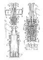
- An electrical connector 10 provides a means of contacting signal wires 12 and drain wires 14 to the pins 16 and 66, respectively, of a three row header 18.
- a metal ground plate 20 is insert molded between two wire receiving dielectric funnel shaped members 22. If a two row connector is desired the ground plate 20 need only be molded to a single dielectric member.
- the entrance end 24 contains wide mouth openings 26 for receiving signal wires 12 and the poly(tetrafluoroethylene) tape 58 from the coax cables 34.
- Exit end 28 contains multiple terminal receiving slot 30. Each slot 30 contains a female terminal 22.
- the metal ground plate 20 has parallel rows of openings 21 adapted to receive legs 41 of ground strain relief bars 40 and 42.
- the coax cable 34 has an outer insulation layer 36. This layer is penetrated with holes 38 adapted to receive ground strain relief bars 40 and 42. Each strain relief bar 40 and 42 contains latches 44 capable of engaging slots 46 in a housing shell 48 which fits over the connectors 10.
- the housing shell 48 containing the connector 10 is attached to the shroud 50 of the three row header 18 by means of jack screws 52. Holes 54 in the housing shell 48 and holes 56 in the shroud 50 accommodate the jack screws 52.
- the coax cable 34 is prepared for the connector 10 by first punching holes 38 between each repeating unit of signal wire 12 and drain wires 14. Then the end of the insulation 36 is stripped to expose a poly(tetrafluoroethylene) jacket-58.
- the signal wire 12 surrounded by the poly(tetrafluoroethylene) jacket 58 is inserted into the wire receiving funnel entrance end 24 through the mouth openings 26.
- the diminishing cross section of the channel within the funnel 22 retains the poly(tetrafluoroethylene) jacket 58 and the wire 12 proceeds through the channel to the exit end 28 of the funnel member 22 to engage a terminal 32 retained within the slots 30.
- the wire 12 is soldered in zone 60 to the terminal 32.
- the ground wires 14 are soldered in zone 62 to the bars 40 and 42, respectively, as shown in FIG. 3.
- the ground plate 20 has a pair of tuning forks 64 on the end opposite from the solder zones 62.
- the tuning forks 64 engage a middle pin 66 in the three row header 18.
- the top and bottom row of pins 16 in the header 18 engage female end 68 within the terminal 32.
- FIG. 4 shows a typical terminal 32.
- a wire guide 70 receives the signal wire 12 and is soldered in zone 60.
- a deflection member 72 facilitates contact with the wire 12.
- a lance 74 retains the terminal 32 within the slot 30.
- a spring 76 within the terminal 32 holds the pin 16 within the terminal 32.
- FIG. 3b A section just behind the entrance end 24 of connector 10 is shown in FIG. 3b.
- the front 78 of the housing shell 48 is shown in FIG. 3a.
- FIG. 6 shows the aluminized MYLAR@ 86 surrounding the ground or drain wires 14, the poly(tetrafluoroethylene) inner covering 58 and the signal wire 12.
- FIG. 7 shows details of the holes 38 punched into the ribbon cable 34.
- the header 18 and funnel 22 can be made of any high temperature resistant plastic such as polyphenylene sulphide.
- the shroud 48 can be made of electric grade nylon.
- the ground plate 20 and the terminal 32 can be made of electrically conductive metals such as phosphor bronze, cupro-nickel or beryllium copper.
Landscapes
- Coupling Device And Connection With Printed Circuit (AREA)
- Multi-Conductor Connections (AREA)
- Details Of Connecting Devices For Male And Female Coupling (AREA)
- Connector Housings Or Holding Contact Members (AREA)
Claims (6)
einen Aufnahme-Kontaktanschluß (32) hat, der derart beschaffen ist, daß er mit einem Signalleiter des Kabels verbindbar ist, dadurch gekennzeichnet, daß das Eintrittsende jedes kanalförmigen dielektrischen Elements eine trichterförmige Gestalt (26) hat, die eine sich verjüngende Querschnittsfläche zur Aufnahme eines Signalleiters und des umgebenden Mantels hat, daß das Austrittsende einen Schlitz (30) hat, um den Kontaktanschluß aufzunehmen, und daß eine metallische Erdungsplatte (20) vorgesehen ist, deren Mittelabschnitt einsatzgegossen in die Reihe der dielektrischen Elemente ist, und die so beschaffen ist, daß sie mit den Drain-Leitern verbindbar ist.
Priority Applications (1)
| Application Number | Priority Date | Filing Date | Title |
|---|---|---|---|
| AT82200950T ATE17537T1 (de) | 1981-07-24 | 1982-07-23 | Zwei- oder dreireihiger koaxialkabelverbinder. |
Applications Claiming Priority (2)
| Application Number | Priority Date | Filing Date | Title |
|---|---|---|---|
| US06/286,557 US4406512A (en) | 1981-07-24 | 1981-07-24 | Triple row coax cable connector |
| US286557 | 1988-12-19 |
Publications (2)
| Publication Number | Publication Date |
|---|---|
| EP0072063A1 EP0072063A1 (de) | 1983-02-16 |
| EP0072063B1 true EP0072063B1 (de) | 1986-01-15 |
Family
ID=23099138
Family Applications (1)
| Application Number | Title | Priority Date | Filing Date |
|---|---|---|---|
| EP82200950A Expired EP0072063B1 (de) | 1981-07-24 | 1982-07-23 | Zwei- oder dreireihiger Koaxialkabelverbinder |
Country Status (8)
| Country | Link |
|---|---|
| US (1) | US4406512A (de) |
| EP (1) | EP0072063B1 (de) |
| JP (1) | JPS5918833B2 (de) |
| KR (1) | KR860002125B1 (de) |
| AT (1) | ATE17537T1 (de) |
| DE (1) | DE3268540D1 (de) |
| HK (1) | HK52088A (de) |
| SG (1) | SG17888G (de) |
Families Citing this family (52)
| Publication number | Priority date | Publication date | Assignee | Title |
|---|---|---|---|---|
| US4494816A (en) * | 1983-07-27 | 1985-01-22 | At&T Bell Laboratories | Coaxial cable connector |
| JPS6121713U (ja) * | 1984-07-10 | 1986-02-07 | 井関農機株式会社 | 粒状物の移送装置 |
| JPS61248375A (ja) * | 1985-04-25 | 1986-11-05 | アンプ インコ−ポレ−テツド | 電気コネクタ |
| US4806110A (en) * | 1986-06-19 | 1989-02-21 | Labinal Components And Systems, Inc. | Electrical connectors |
| JPS6343273A (ja) * | 1986-08-08 | 1988-02-24 | ヒロセ電機株式会社 | 複数層多心フラットケ−ブル用電気コネクタおよびその結線方法 |
| JPS6341784A (ja) * | 1986-08-08 | 1988-02-23 | 鹿島建設株式会社 | 冷凍倉庫 |
| US5057028A (en) * | 1986-11-18 | 1991-10-15 | E. I. Du Pont De Nemours And Company | Receptacle having a nosepeice to receive cantilevered spring contacts |
| US5169324A (en) * | 1986-11-18 | 1992-12-08 | Lemke Timothy A | Plug terminator having a grounding member |
| US4824383A (en) * | 1986-11-18 | 1989-04-25 | E. I. Du Pont De Nemours And Company | Terminator and corresponding receptacle for multiple electrical conductors |
| US4762500A (en) * | 1986-12-04 | 1988-08-09 | Amp Incorporated | Impedance matched electrical connector |
| US5704794A (en) * | 1986-12-29 | 1998-01-06 | Labinal Components And Systems, Inc. | Electrical connectors |
| US4781620A (en) * | 1987-02-18 | 1988-11-01 | Minnesota Mining And Manufacturing Company | Flat ribbon coaxial cable connector system |
| US4747787A (en) * | 1987-03-09 | 1988-05-31 | Amp Incorporated | Ribbon cable connector |
| US4767345A (en) * | 1987-03-27 | 1988-08-30 | Amp Incorporated | High-density, modular, electrical connector |
| US4776806A (en) * | 1987-07-10 | 1988-10-11 | E. I. Du Pont De Nemours And Company | Low-profile connector assembly |
| JPS6431361A (en) * | 1987-07-15 | 1989-02-01 | Minnesota Mining & Mfg | Electric connection connector |
| CA1300700C (en) * | 1988-01-26 | 1992-05-12 | Kouji Ishikawa | Connector apparatus for high density coaxial cables |
| US4887977A (en) * | 1988-06-15 | 1989-12-19 | E. I. Dupont De Nemours And Company | Cable connector haing a resilient cover |
| US4834674A (en) * | 1988-06-23 | 1989-05-30 | Amp Incorporated | Electrical cable assembly with selected side cable entry |
| JPH0237678A (ja) * | 1988-07-28 | 1990-02-07 | Honda Tsushin Kogyo Kk | フラットケーブル用コネクタ |
| JPH0333977U (de) * | 1989-08-11 | 1991-04-03 | ||
| US4927366A (en) * | 1989-09-08 | 1990-05-22 | Environwear, Inc. | Fused electrical connector with sewing wings |
| US5032705A (en) * | 1989-09-08 | 1991-07-16 | Environwear, Inc. | Electrically heated garment |
| US5203079A (en) * | 1991-11-13 | 1993-04-20 | Molex Incorporated | Method of terminating miniature coaxial electrical connector |
| US5186656A (en) * | 1991-11-13 | 1993-02-16 | Molex Incorporated | Miniature coaxial electrical connector |
| US5176538A (en) * | 1991-12-13 | 1993-01-05 | W. L. Gore & Associates, Inc. | Signal interconnector module and assembly thereof |
| JPH0718918A (ja) * | 1993-07-06 | 1995-01-20 | Kajima Corp | コア壁を有する高層建築物の耐震構造 |
| JPH0734717A (ja) * | 1993-07-21 | 1995-02-03 | Kajima Corp | コア壁を有する高層建築物の耐震構造 |
| JP3007055U (ja) * | 1994-04-28 | 1995-02-07 | 有限会社柄澤産業 | 茸培養基用搬送コンベア |
| US6033238A (en) * | 1997-05-30 | 2000-03-07 | The Whitaker Corporation | Ribbon cable connector with ground bus |
| US5882227A (en) * | 1997-09-17 | 1999-03-16 | Intercon Systems, Inc. | Controlled impedance connector block |
| US6004150A (en) * | 1997-12-31 | 1999-12-21 | Cisco Technology, Inc. | Configurable electrical shunt for a computer cable |
| US5980308A (en) * | 1998-05-13 | 1999-11-09 | Hu; Yu-Tung | Female socket of a connector |
| US6857899B2 (en) | 1999-10-08 | 2005-02-22 | Tensolite Company | Cable structure with improved grounding termination in the connector |
| US6217372B1 (en) | 1999-10-08 | 2001-04-17 | Tensolite Company | Cable structure with improved grounding termination in the connector |
| US6273749B1 (en) * | 2000-03-09 | 2001-08-14 | All Best Electronics Co., Ltd. | Connector |
| US6428344B1 (en) | 2000-07-31 | 2002-08-06 | Tensolite Company | Cable structure with improved termination connector |
| US6786762B2 (en) * | 2001-08-20 | 2004-09-07 | The Ludlow Company, Lp | Cable assembly module with compressive connector |
| US6602092B2 (en) * | 2001-08-20 | 2003-08-05 | Ludlow Company Lp | Cable assembly module with compressive connector |
| JP4124760B2 (ja) * | 2003-12-22 | 2008-07-23 | モレックス インコーポレーテッド | 同軸ケーブル用コネクタ及びケーブル保持具 |
| JP2006244732A (ja) * | 2005-02-28 | 2006-09-14 | Molex Inc | ケーブル用コネクタ |
| US20070141871A1 (en) * | 2005-12-19 | 2007-06-21 | 3M Innovative Properties Company | Boardmount header to cable connector assembly |
| DE102006007621A1 (de) | 2006-02-18 | 2007-08-23 | Clariant International Limited | Diketopyrrolopyrrol-Pigmente mit erhöhten Echtheiten und Verfahren zu deren Herstellung |
| EP2070163A1 (de) * | 2006-09-14 | 2009-06-17 | 3M Innovative Properties Company | Elektrische steckverbinderanordnung |
| JP4879071B2 (ja) * | 2007-04-02 | 2012-02-15 | タイコエレクトロニクスジャパン合同会社 | シールド電線の接続構造 |
| US7540773B2 (en) * | 2007-06-08 | 2009-06-02 | Hon Hai Precision Ind. Co., Ltd. | Connector assembly with improved strain relief structure |
| US7445471B1 (en) | 2007-07-13 | 2008-11-04 | 3M Innovative Properties Company | Electrical connector assembly with carrier |
| US7841776B2 (en) | 2008-09-30 | 2010-11-30 | Apple Inc. | Magnetic connector with optical signal path |
| US9791634B2 (en) | 2008-09-30 | 2017-10-17 | Apple Inc. | Magnetic connector with optical signal path |
| CN201708323U (zh) * | 2010-04-19 | 2011-01-12 | 富士康(昆山)电脑接插件有限公司 | 线缆连接器组件 |
| JP2012064338A (ja) * | 2010-09-14 | 2012-03-29 | Fujitsu Ltd | 同軸ケーブルの端末構造、コネクタ及び基板ユニット |
| JP6320629B2 (ja) * | 2015-04-14 | 2018-05-09 | 三菱電機株式会社 | 多極コネクタおよびコネクタ装置 |
Family Cites Families (11)
| Publication number | Priority date | Publication date | Assignee | Title |
|---|---|---|---|---|
| FR1444579A (fr) * | 1964-08-24 | 1966-07-01 | Amp Inc | Connecteur pour câble coaxial |
| US3550066A (en) * | 1968-09-19 | 1970-12-22 | Amp Inc | Connector for multiple conductor cable |
| US3864011A (en) * | 1973-08-27 | 1975-02-04 | Amp Inc | Coaxial ribbon cable connector |
| US4040704A (en) * | 1974-11-29 | 1977-08-09 | Amp Incorporated | Coaxial ribbon cable connector |
| US3963319A (en) * | 1974-12-12 | 1976-06-15 | Amp Incorporated | Coaxial ribbon cable terminator |
| US3958852A (en) * | 1975-04-15 | 1976-05-25 | Bell Telephone Laboratories, Incorporated | Electrical connector |
| US3954321A (en) * | 1975-08-13 | 1976-05-04 | The United States Of America As Represented By The United States Energy Research And Development Administration | Miniature electrical connector |
| US4035050A (en) * | 1976-05-05 | 1977-07-12 | Amp Incorporated | Ribbon coaxial cable connector |
| US4094564A (en) * | 1977-03-17 | 1978-06-13 | A P Products Incorporated | Multiple conductor electrical connector with ground bus |
| US4157612A (en) * | 1977-12-27 | 1979-06-12 | Bell Telephone Laboratories, Incorporated | Method for improving the transmission properties of a connectorized flat cable interconnection assembly |
| US4169650A (en) * | 1978-09-20 | 1979-10-02 | Eby Company | Wire-wrap assembly connector |
-
1981
- 1981-07-24 US US06/286,557 patent/US4406512A/en not_active Expired - Lifetime
-
1982
- 1982-07-22 KR KR8203274A patent/KR860002125B1/ko active
- 1982-07-23 DE DE8282200950T patent/DE3268540D1/de not_active Expired
- 1982-07-23 AT AT82200950T patent/ATE17537T1/de not_active IP Right Cessation
- 1982-07-23 JP JP57127789A patent/JPS5918833B2/ja not_active Expired
- 1982-07-23 EP EP82200950A patent/EP0072063B1/de not_active Expired
-
1988
- 1988-03-15 SG SG178/88A patent/SG17888G/en unknown
- 1988-07-07 HK HK520/88A patent/HK52088A/xx unknown
Also Published As
| Publication number | Publication date |
|---|---|
| EP0072063A1 (de) | 1983-02-16 |
| DE3268540D1 (en) | 1986-02-27 |
| KR860002125B1 (ko) | 1986-11-26 |
| ATE17537T1 (de) | 1986-02-15 |
| JPS5826467A (ja) | 1983-02-16 |
| SG17888G (en) | 1988-07-08 |
| HK52088A (en) | 1988-07-15 |
| JPS5918833B2 (ja) | 1984-05-01 |
| US4406512A (en) | 1983-09-27 |
| KR840000992A (ko) | 1984-03-26 |
Similar Documents
| Publication | Publication Date | Title |
|---|---|---|
| EP0072063B1 (de) | Zwei- oder dreireihiger Koaxialkabelverbinder | |
| KR100808728B1 (ko) | 고속 커넥터 | |
| US4605276A (en) | Two row coaxial cable connector | |
| KR950007425B1 (ko) | 전기 커넥터 | |
| US4533199A (en) | IDC termination for coaxial cable | |
| US4451099A (en) | Electrical connector having commoning member | |
| KR890004498B1 (ko) | 잭-플러그 조립체 | |
| US6338652B1 (en) | Low profile cable connector with grounding means | |
| EP0118168B2 (de) | Elektrischer Steckverbinder und Steckdose dafür | |
| EP0607920B1 (de) | Elektrischer Verbinder für Stromversorgungs- und Signalkontakte | |
| US7467969B2 (en) | Cable connector assembly with wire management member | |
| US4556275A (en) | Electrical panelboard connector | |
| US4701139A (en) | Shielded cable assembly | |
| KR20060135964A (ko) | 저 인덕턴스 차폐 커넥터 | |
| US20080293292A1 (en) | Cable connector assembly with wire management member thereof | |
| US6544050B1 (en) | Electrical cable connector assembly | |
| EP0653815B1 (de) | Elektrischer Verbinder mit Erdklemme für Kabelabschirmung | |
| US11888267B2 (en) | Electrical connector assembly including matable board connector and cable connector with improved grounding bar | |
| US6250959B1 (en) | Connector for coaxial cables with very fine conductors | |
| US3509513A (en) | Cables connecting assembly | |
| EP0624928B1 (de) | Abgeschirmte elektrische Verbinderanordnung | |
| US6808410B1 (en) | Cable connector assembly having pulling mechanism | |
| US20100065327A1 (en) | Cable assembly with molded grounding bar and method of making same | |
| US4458967A (en) | Connector for shielded flat cable | |
| CN115668659A (zh) | 具有用于阻抗控制的介电蛤壳式连接器的电缆组件 |
Legal Events
| Date | Code | Title | Description |
|---|---|---|---|
| PUAI | Public reference made under article 153(3) epc to a published international application that has entered the european phase |
Free format text: ORIGINAL CODE: 0009012 |
|
| AK | Designated contracting states |
Designated state(s): AT BE CH DE FR GB IT LI LU NL SE |
|
| 17P | Request for examination filed |
Effective date: 19830714 |
|
| ITF | It: translation for a ep patent filed | ||
| GRAA | (expected) grant |
Free format text: ORIGINAL CODE: 0009210 |
|
| AK | Designated contracting states |
Designated state(s): AT BE CH DE FR GB IT LI LU NL SE |
|
| REF | Corresponds to: |
Ref document number: 17537 Country of ref document: AT Date of ref document: 19860215 Kind code of ref document: T |
|
| REF | Corresponds to: |
Ref document number: 3268540 Country of ref document: DE Date of ref document: 19860227 |
|
| ET | Fr: translation filed | ||
| PG25 | Lapsed in a contracting state [announced via postgrant information from national office to epo] |
Ref country code: LU Free format text: LAPSE BECAUSE OF NON-PAYMENT OF DUE FEES Effective date: 19860731 |
|
| PLBE | No opposition filed within time limit |
Free format text: ORIGINAL CODE: 0009261 |
|
| STAA | Information on the status of an ep patent application or granted ep patent |
Free format text: STATUS: NO OPPOSITION FILED WITHIN TIME LIMIT |
|
| 26N | No opposition filed | ||
| PGFP | Annual fee paid to national office [announced via postgrant information from national office to epo] |
Ref country code: FR Payment date: 19900525 Year of fee payment: 9 |
|
| PGFP | Annual fee paid to national office [announced via postgrant information from national office to epo] |
Ref country code: DE Payment date: 19900528 Year of fee payment: 9 |
|
| PGFP | Annual fee paid to national office [announced via postgrant information from national office to epo] |
Ref country code: CH Payment date: 19900530 Year of fee payment: 9 |
|
| PGFP | Annual fee paid to national office [announced via postgrant information from national office to epo] |
Ref country code: SE Payment date: 19900531 Year of fee payment: 9 |
|
| PGFP | Annual fee paid to national office [announced via postgrant information from national office to epo] |
Ref country code: BE Payment date: 19900607 Year of fee payment: 9 |
|
| PGFP | Annual fee paid to national office [announced via postgrant information from national office to epo] |
Ref country code: LU Payment date: 19900627 Year of fee payment: 9 |
|
| PGFP | Annual fee paid to national office [announced via postgrant information from national office to epo] |
Ref country code: GB Payment date: 19900629 Year of fee payment: 9 |
|
| ITTA | It: last paid annual fee | ||
| PGFP | Annual fee paid to national office [announced via postgrant information from national office to epo] |
Ref country code: NL Payment date: 19900731 Year of fee payment: 9 Ref country code: AT Payment date: 19900731 Year of fee payment: 9 |
|
| PG25 | Lapsed in a contracting state [announced via postgrant information from national office to epo] |
Ref country code: GB Effective date: 19910723 Ref country code: AT Effective date: 19910723 |
|
| PG25 | Lapsed in a contracting state [announced via postgrant information from national office to epo] |
Ref country code: SE Effective date: 19910724 |
|
| PG25 | Lapsed in a contracting state [announced via postgrant information from national office to epo] |
Ref country code: LI Effective date: 19910731 Ref country code: CH Effective date: 19910731 Ref country code: BE Effective date: 19910731 |
|
| BERE | Be: lapsed |
Owner name: E.I. DU PONT DE NEMOURS AND CY Effective date: 19910731 |
|
| PG25 | Lapsed in a contracting state [announced via postgrant information from national office to epo] |
Ref country code: NL Effective date: 19920201 |
|
| NLV4 | Nl: lapsed or anulled due to non-payment of the annual fee | ||
| GBPC | Gb: european patent ceased through non-payment of renewal fee | ||
| PG25 | Lapsed in a contracting state [announced via postgrant information from national office to epo] |
Ref country code: FR Effective date: 19920331 |
|
| REG | Reference to a national code |
Ref country code: CH Ref legal event code: PL |
|
| PG25 | Lapsed in a contracting state [announced via postgrant information from national office to epo] |
Ref country code: DE Effective date: 19920401 |
|
| REG | Reference to a national code |
Ref country code: FR Ref legal event code: ST |
|
| EUG | Se: european patent has lapsed |
Ref document number: 82200950.2 Effective date: 19920210 |