EP0071538B1 - Appareil de transfert d'éléments de reproduction animale, tels que des embryons - Google Patents
Appareil de transfert d'éléments de reproduction animale, tels que des embryons Download PDFInfo
- Publication number
- EP0071538B1 EP0071538B1 EP82401420A EP82401420A EP0071538B1 EP 0071538 B1 EP0071538 B1 EP 0071538B1 EP 82401420 A EP82401420 A EP 82401420A EP 82401420 A EP82401420 A EP 82401420A EP 0071538 B1 EP0071538 B1 EP 0071538B1
- Authority
- EP
- European Patent Office
- Prior art keywords
- tube
- reservoir tube
- main body
- rigid
- sheath
- Prior art date
- Legal status (The legal status is an assumption and is not a legal conclusion. Google has not performed a legal analysis and makes no representation as to the accuracy of the status listed.)
- Expired
Links
- 241001465754 Metazoa Species 0.000 title claims abstract description 6
- 210000002257 embryonic structure Anatomy 0.000 title description 2
- 210000001161 mammalian embryo Anatomy 0.000 description 17
- 239000000725 suspension Substances 0.000 description 10
- 229910001220 stainless steel Inorganic materials 0.000 description 8
- 239000010935 stainless steel Substances 0.000 description 8
- 230000001681 protective effect Effects 0.000 description 5
- 210000000582 semen Anatomy 0.000 description 5
- 210000003756 cervix mucus Anatomy 0.000 description 4
- 210000003679 cervix uteri Anatomy 0.000 description 4
- 230000006378 damage Effects 0.000 description 4
- 210000001215 vagina Anatomy 0.000 description 4
- 210000003097 mucus Anatomy 0.000 description 3
- 229920003023 plastic Polymers 0.000 description 3
- 239000004033 plastic Substances 0.000 description 3
- 229920000915 polyvinyl chloride Polymers 0.000 description 3
- 239000004800 polyvinyl chloride Substances 0.000 description 3
- 230000001850 reproductive effect Effects 0.000 description 3
- 210000004291 uterus Anatomy 0.000 description 3
- 238000004500 asepsis Methods 0.000 description 2
- 238000009395 breeding Methods 0.000 description 2
- 230000001488 breeding effect Effects 0.000 description 2
- 229920002457 flexible plastic Polymers 0.000 description 2
- 230000003902 lesion Effects 0.000 description 2
- 238000012423 maintenance Methods 0.000 description 2
- 239000000463 material Substances 0.000 description 2
- 239000002184 metal Substances 0.000 description 2
- 238000012986 modification Methods 0.000 description 2
- 230000004048 modification Effects 0.000 description 2
- 210000004877 mucosa Anatomy 0.000 description 2
- 241001415961 Gaviidae Species 0.000 description 1
- 241000735470 Juncus Species 0.000 description 1
- 235000014443 Pyrus communis Nutrition 0.000 description 1
- 208000027418 Wounds and injury Diseases 0.000 description 1
- 239000011324 bead Substances 0.000 description 1
- 238000005452 bending Methods 0.000 description 1
- 238000011109 contamination Methods 0.000 description 1
- 238000003890 embryo preservation Methods 0.000 description 1
- 230000012173 estrus Effects 0.000 description 1
- 239000000284 extract Substances 0.000 description 1
- 239000012530 fluid Substances 0.000 description 1
- 239000011521 glass Substances 0.000 description 1
- 238000002513 implantation Methods 0.000 description 1
- 239000012535 impurity Substances 0.000 description 1
- 208000014674 injury Diseases 0.000 description 1
- 230000009027 insemination Effects 0.000 description 1
- 238000012432 intermediate storage Methods 0.000 description 1
- 210000004400 mucous membrane Anatomy 0.000 description 1
- 238000005057 refrigeration Methods 0.000 description 1
- 210000005000 reproductive tract Anatomy 0.000 description 1
- 238000010079 rubber tapping Methods 0.000 description 1
- 238000005070 sampling Methods 0.000 description 1
- 239000007787 solid Substances 0.000 description 1
- 230000001954 sterilising effect Effects 0.000 description 1
- 238000004659 sterilization and disinfection Methods 0.000 description 1
- 238000003860 storage Methods 0.000 description 1
Images


Classifications
-
- A—HUMAN NECESSITIES
- A61—MEDICAL OR VETERINARY SCIENCE; HYGIENE
- A61D—VETERINARY INSTRUMENTS, IMPLEMENTS, TOOLS, OR METHODS
- A61D19/00—Instruments or methods for reproduction or fertilisation
- A61D19/04—Instruments or methods for reproduction or fertilisation for embryo transplantation
-
- A—HUMAN NECESSITIES
- A61—MEDICAL OR VETERINARY SCIENCE; HYGIENE
- A61D—VETERINARY INSTRUMENTS, IMPLEMENTS, TOOLS, OR METHODS
- A61D19/00—Instruments or methods for reproduction or fertilisation
- A61D19/02—Instruments or methods for reproduction or fertilisation for artificial insemination
- A61D19/027—Devices for injecting semen into animals, e.g. syringes, guns, probes
Definitions
- the present invention relates to devices for transferring elements of animal reproduction, such as embryos (from a donor reproductive female and to be placed in a carrier female) or animal semen (taken from a male for the purpose of 'artificial insemination). It relates more particularly to devices of the purely mechanical ejection type, comprising a hollow and rigid main body, of generally cylindrical shape, at one end of which is fixed a flexible tube which extends the main body outwards, this tube having to serve as reservoir to the reproduction elements, while this main body internally receives, at its other end, a piston rod with which is associated a sliding piston, the free end of the reservoir tube comprising, moreover, an ejection nozzle with axial passage, the body being able, moreover, to be advantageously surrounded externally, over at least a large part of its length, by a protective sheath fixed on it, which is changed at each operation, which avoids sterilization of the apparatus.
- the tube -reservoir is housed, over most of its length, inside the rigid body, and the piston is directly actuated by the end of the rod whose length is roughly equal to that of the body (similarly besides that of the protective sheath, when provided, in which case the end piece is, moreover, interposed between the end of the reservoir tube and that of the sheath which both protrude slightly from the body) .
- the entire apparatus is rigid over its entire length and the rod and piston assembly is used at least to push the reproductive elements into the womb of the breeding female, in the case of semen , in that of the carrier female, in the case of an embryo.
- This same rod and piston assembly may, moreover, have already been used, in addition, for the aspiration of the semen in a particular embodiment of the first case.
- it is a reservoir tube previously filled with semen, or a suspension containing the embryo, and in general stored under refrigeration, after removal from the male or the breeding female, which is fixed on the body of the device, a tampon which seals the end of the tube then serving as a piston during ejection.
- the free end of this device should, in principle, be inserted beyond the vagina and cervix, as far as possible inside the uterus of the animal, to ensure a deep deposit of the semen or embryo and therefore facilitate reproduction or implantation.
- the uterine lining is extremely fragile (particularly in the case of an embryo transfer, which should normally take place outside the period of oestrus), so that these known devices risk, made of their rigid end, to cause a lesion of this mucosa with all the consequences that this entails.
- the known devices for example the aforementioned patent FR -A? 2477006
- the known devices in fact only allow the establishment of the embryo in the carrier female, the collection on the female reproductive using an entirely separate device and operating of a completely different type, since by fluid circulation (such as that described in the French patent of holders FP-AN No. 2477005).
- the delivery device must receive a reservoir tube already filled with the embryo suspension.
- the main object of the present invention is to minimize the risk of damage to the uterine lining and, for this purpose, it relates to a transfer device of the aforementioned type, in which a rigid main body is surrounded by a second rigid body. characterized in that this main body can slide inside said second body which has approximately the same length as the latter, while the piston rod comprises a front section which is flexible and has a length at least equal to that of the tank tube.
- the device can, in in addition, include a fixing sleeve rigid which can surround the reservoir tube and which has, at one end, means for retaining the nozzle fixed to the front end of the reservoir tube, and at the other end, means for pressing on the front end of the outer body, this sheath favoring the maintenance of the reservoir tube, which is flexible, while it is fixed to the end of the main body, for example by interlocking, while simultaneously ensuring perfect asepsis of the operation .
- a fixing sleeve rigid which can surround the reservoir tube and which has, at one end, means for retaining the nozzle fixed to the front end of the reservoir tube, and at the other end, means for pressing on the front end of the outer body, this sheath favoring the maintenance of the reservoir tube, which is flexible, while it is fixed to the end of the main body, for example by interlocking, while simultaneously ensuring perfect asepsis of the operation .
- a protective sheath it can very advantageously be arranged around the external body, so as to protrude slightly at the front thereof, by presenting at its front end a rounded inner hem, while it is, moreover, fixed on the same outer body at its opposite end, which allows, when the main body recedes, to fully return the reservoir tube inside this sheath , the hem of the latter avoiding any lesion of the mucosa during introduction into the uterus.
- the end piece fixed to the end of the reservoir tube has, at the front, a rigid spherical head, which can pass elastically through the hem of the sheath, while its central passage opens out.
- the spherical head due to its shape, progresses easily and without damage in the uterine lumen.
- the object of the invention is also to make it possible to carry out, using the same apparatus, the aspiration sampling in the empty reservoir tube of the suspension containing the embryo (s), and this in an intermediate storage container, without that it is necessary to use other specialized devices for this purpose.
- the apparatus according to the invention is, furthermore, characterized in that the flexible front section of the piston rod carries, at its front end, the ejection piston and is separated from the rear section of the rod which is rigid.
- the subassembly of the device constituted by the reservoir tube and the flexible front section of the rod can be separated from the rest of the device to operate like a syringe for aspirating, in a storage container, the suspension containing the embryo, this sub-assembly then being reattached to the rest of the device to allow introduction and ejection in the manner already indicated.
- the apparatus may also comprise a rigid guide sleeve which can surround the reservoir tube and which has, at one end, means for retaining the end of the reservoir tube opposite to that which must receive the tip, this sheath favoring the maintenance of the reservoir tube during the aspiration of the suspension, which avoids, during handling, any twisting which could block the aspiration of the embryo, while ensuring the asepsis of this operation.
- a rigid guide sleeve which can surround the reservoir tube and which has, at one end, means for retaining the end of the reservoir tube opposite to that which must receive the tip, this sheath favoring the maintenance of the reservoir tube during the aspiration of the suspension, which avoids, during handling, any twisting which could block the aspiration of the embryo, while ensuring the asepsis of this operation.
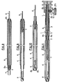
- the apparatus represented by the figures essentially consists of an external body 1 (fig. 1), a main body 2 (fig. 2), a rigid piston rod element 3 (fig. 3), a reservoir tube 4 (fig. 4), a flexible front section of piston rod 5 (fig. 5), a nozzle 6 for the reservoir tube (fig. 6), and an ejection piston 7 (fig. 7), these various elements, shown separately in Figs. 1 to 7, being, moreover, supplemented by a suction and fixing tube 8 (fig. 8 to 12), a protective sheath 9 (fig. 11 to 13), and finally a clamping screw 10 (fig . 11 to 13).
- the outer body 1 is a stainless steel body, hollow and rigid, of generally cylindrical shape, and more particularly constituted by a tube 1 a extending over its entire length and on the rear end 1 b from which is force fitted.
- a sheath 1c also made of stainless steel, which has a frustoconical interlocking surface 1 d at the front, converging towards the front and, at the rear, an operating head 1 e, of annular shape, which has a radial tapping 1f also passing through the tube 1a, so as to open into the lumen of the latter, the central portion of this sheath 1c finally connecting it radially and outwards to the frustoconical bearing 1 d by a shoulder 1 g.
- the main body 2 (fig. 2) is also formed by a stainless steel body, hollow and rigid, and also of generally cylindrical shape, but more particularly constituted by a tube 2a whose outside diameter corresponds to the inside diameter of the tube 1a, and at the rear end 2b of which is fixed an operating head 2c, of annular shape, and also made of stainless steel, while at its front end, this same tube has three distinct annular grooves separated by two interlocking surfaces frustoconical 2d and 2e, which converge forward and which connect to the grooves behind them by shoulders 2f.
- the tube 2a is relatively longer than the tube 1a of the outer body, so that when the main body 2 is introduced into this outer body 1, as shown in FIG.
- the rear piston rod element 3 (FIG. 3) is also constituted by a hollow and rigid tube 3a, made of stainless steel, on the rear end 3b of which is fixed an operating head of annular shape 3c, also in stainless steel, while at its front end 3d, this tube has a wider bore 3e over a certain length.
- the outer diameter of this tube 3a corresponds to the inner diameter of the tube 2a of the main body, and its length is somewhat shorter than that of the outer body 1, so that when this rear piston rod element 3 is introduced into the inside the main body 2 until, as also shown in FIG. 11, the two gripping heads 2c and 3c, forming abutment means, come to bear one on the other, the front end of the tube 3 remains slightly set back relative to that of the body 1.
- the reservoir tube 4 (fig. 4) is a perfectly cylindrical tube over its entire length, and made of a flexible plastic material, such as flexible polyvinyl chloride. Its outer diameter is substantially equal to that of the main body 2 and its inner diameter substantially equal to the diameter of the grooves 2g, located at the front end 2h of this tube, so that, as shown in fig. 11, the rear end 4a of the reservoir tube can be fitted elastically over the two frustoconical bearing surfaces 2d and 2e of the main body, until it comes into abutment against the rear shoulder of the rear groove 2g.
- the length of this tube is provided so as to correspond, on the one hand, to a normal volume of the suspension containing the embryo (s) that this tube must contain, and, on the other hand, to the average length of the genital tract of the female.
- the flexible front section of piston rod 5 (fig. 5) consists of a solid rod or a rod, also made of flexible plastic, such as flexible polyvinyl chloride.
- the diameter of this rod is quite clearly less than the inside diameter of the reservoir tube 4, so that, when this rod is disposed inside this tube, as shown in FIG. 11, there remains a substantial radial clearance between them, this same diameter of the rod corresponding, moreover, very precisely to the diameter of the bore 3e of the rear piston rod element 3, which allows it to be able to come fully engage it, as shown in fig. 11.
- the length of this rod is approximately of the same order of magnitude as that of the reservoir tube 4.
- the end piece 6 (fig. 6) is a piece of stainless steel, of generally short cylindrical shape and which comprises, at its rear end, a frustoconical interlocking surface 6a, converging towards the rear and separated from the current part cylindrical by a groove 6b, while at its front end is welded a spherical head also made of stainless steel 6c, of slightly larger diameter, a central passage 6d finally extending over the greater part of this endpiece to open axially at the rear, while it opens on the side and at the rear of the spherical head 6c, using a 6th elbow.
- the diameter of the current part of the end piece corresponds to that of the reservoir tube 4, so that, as still shown in FIG. 11, the front end 4b of this tube can come to fit elastically, over the frustoconical surface 6a, and until it comes into abutment against the front shoulder of the groove 6b.
- the piston rod 7 (FIG. 7) is a plastic part, of relatively short cylindrical general shape, comprising at the front a frustoconical head 7a, while at the rear there is arranged axially a blind bore 7b, diameter corresponding to that of the rod 5, so that the front end 5a of the latter can come to fit there, as shown in FIG. 8.
- the protective sheath 9 is a thin cylindrical sheath, made of a semi-rigid plastic material, such as semi-rigid polyvinyl chloride. Its diameter corresponds substantially to that of the current part 1 c of the outer body 1, so that, as shown in FIG. 11, this sheath can come to be fixed elastically, by its rear end 9a, over the frustoconical surface 1d of this body, and until it comes into abutment against the head 1e.
- the length of this sheath is such that, in this latter position, its front end 9b comes substantially at the level of the groove 2g rear of the main body 2, and consequently of the rear edge of the reservoir tube 4 when the latter has come 'fitting over this body 2.
- This same front end 9b of the sheath has a rounded hem 9c, rounded folded inwards, which comes into contact with said rear edge of the tube 4.
- the suction and fixing sleeve 8 (fig. 8) consists of a relatively rigid plastic tube, the length of which is roughly equal to that of the reservoir tube 4, and the current diameter of which is relatively greater than that of this same tube. At one end 8a, this sheath has a cylindrical constriction, with a diameter still greater than that of the tube 4 but corresponding, on the other hand, to that of the hem 9c of the sheath, so that these two parts can bear the one against the other, as shown in fig. 11.
- this sheath has another constriction, of frustoconical shape, the end of which provided with a hem has a diameter corresponding substantially to the diameter of the reservoir tube 4, so as to be able to act as a support either to the latter itself (fig. 4), or to the spherical head 6c of its tip (fig. 10 and 11).
- the screw 10 As for the screw 10 (fig. 11), it has a threaded portion 10a, which can be screwed into the internal thread 1f of the outer body 1, and an operating head 10b.
- the operator positions, using sterilized forceps, the end piece 6 terminated by its spherical head 6c, at the front end 4b of the tube 4, the fixing being done by elastic fitting of the tube 4 on the frustoconical surface 6a (fig. 9).
- the operator introduces the sub-assembly into the same rigid sheath 8, but this time by its opposite end, so that the end piece 6 comes to rest, by its spherical head 6a, against the hem of the frustoconical constriction 8b of this sheath (fig. 10).
- the operator then brings the flexible sub-assembly, held by the rigid sheath, facing the rest of the apparatus consisting of the sheath 9, the external body 1, the main body 2 and the piston rod 3, already introduced respectively. one inside the other, and in support, by their operating heads, as shown in fig. 11, the screw 10, which is fixed in the head 1 of the external body, also passing through a hole 2i in the main body to come to bear at its end on the piston rod 3, which ensures the assembly of the assembly.
- the sheath 8 which came to bear on the hem 9c of the sheath 9
- the operator guides the rear end 4a of the reservoir tube on the frustoconical surfaces 2d and 2e of the main body, up to ensure elastic fitting of this tube on this body (fig. 11).
- the operator releases the screw 10 and very gently pushes, using its head 2c, the main body 2 which carries, on its front end, the reservoir tube 4, in a forward movement, and this as much as necessary so that the nozzle 6 and its lateral ejection orifice 6e reach the optimal ejection position.
- the flexibility of the flexible sub-assembly 4.5 makes it possible to follow the meanders and the curvature of the uterine horn.
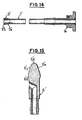
- the body 1 and the sheath 9 of the embodiment described above are replaced by a single piece constituted by a modification of the external body (fig. 14).
- This metal sleeve extends over a length which is of the order of magnitude of its outside diameter and successively presents, in the direction of the free end, a divergent frustoconical surface with a very slight slope 9'a, then a clearly rounded fillet shorter 9'b which is flush with the edge of the tube 1 '.
- This sleeve has an outer surface which is carefully polished, while it is also glued, also carefully, on the end of the tube 1 '.
- This sleeve, projecting from the tube, aims to advantageously replace the rounded hem 9c of the sheath 9 used in the previous embodiment, as will be described later.
- the nozzle 6 of FIG. 6 is, in the present variant, replaced by a tip 6 'which differs from it only in that the spherical head 6c is here replaced by an end 6'a of the tip itself, integrally formed with it and having a pear or shell shape, that is to say successively in the direction of its free end, a bead 6'b of diameter slightly greater than that of the cylindrical body of the end piece, a converging frustoconical part 6 'c and a 6' spherical cap end.
- the endpiece 6 ' has the same structure as the endpiece of FIG. 6 (socket 6a, groove 6b and central passage 6d), as well as the tube 1 'of fig. 14 which also presents the other elements of the tube of the external body of FIG. 1 (socket 1 d and head 1 e).
- the shell-shaped head 6 ′ a of the nozzle 6 ′ comes to engage inside the end of the body outside 1 '(as in the previous embodiment, the spherical head 6a came into contact inside the hem 9c of the sheath), so as to ensure a perfect seal preventing the rise of vaginal mucus and cervical mucus . perfect preventing the rise of vaginal mucus and cervical mucus.
Landscapes
- Health & Medical Sciences (AREA)
- Life Sciences & Earth Sciences (AREA)
- Veterinary Medicine (AREA)
- Animal Behavior & Ethology (AREA)
- Engineering & Computer Science (AREA)
- Reproductive Health (AREA)
- Wood Science & Technology (AREA)
- Zoology (AREA)
- Transplantation (AREA)
- General Health & Medical Sciences (AREA)
- Public Health (AREA)
- Prostheses (AREA)
- Feeding And Watering For Cattle Raising And Animal Husbandry (AREA)
- Medicines Containing Material From Animals Or Micro-Organisms (AREA)
- Micro-Organisms Or Cultivation Processes Thereof (AREA)
- Infusion, Injection, And Reservoir Apparatuses (AREA)
Priority Applications (1)
| Application Number | Priority Date | Filing Date | Title |
|---|---|---|---|
| AT82401420T ATE11637T1 (de) | 1981-07-31 | 1982-07-29 | Geraet fuer die verpflanzung von elementen fuer die tierfortpflanzung, wie embrios. |
Applications Claiming Priority (2)
| Application Number | Priority Date | Filing Date | Title |
|---|---|---|---|
| FR8114930A FR2510393A1 (fr) | 1981-07-31 | 1981-07-31 | Appareil de transfert d'elements de reproduction animale, tels que des embryons |
| FR8114930 | 1981-07-31 |
Publications (2)
| Publication Number | Publication Date |
|---|---|
| EP0071538A1 EP0071538A1 (fr) | 1983-02-09 |
| EP0071538B1 true EP0071538B1 (fr) | 1985-02-06 |
Family
ID=9261049
Family Applications (1)
| Application Number | Title | Priority Date | Filing Date |
|---|---|---|---|
| EP82401420A Expired EP0071538B1 (fr) | 1981-07-31 | 1982-07-29 | Appareil de transfert d'éléments de reproduction animale, tels que des embryons |
Country Status (4)
| Country | Link |
|---|---|
| EP (1) | EP0071538B1 (https=) |
| AT (1) | ATE11637T1 (https=) |
| DE (1) | DE3262220D1 (https=) |
| FR (1) | FR2510393A1 (https=) |
Families Citing this family (38)
| Publication number | Priority date | Publication date | Assignee | Title |
|---|---|---|---|---|
| FR2556596B1 (fr) * | 1983-12-16 | 1986-12-05 | Cassou Robert | Instruments d'action gynecologique, notamment de transfert d'embryons |
| FR2574656B1 (fr) * | 1984-12-13 | 1988-08-05 | Cassou Robert | Sonde gynecologique notamment pour l'injection de semence ou d'embryons dans la cavite des animaux, tels que les juments |
| FR2575063B1 (fr) * | 1984-12-21 | 1988-07-01 | Cassou Robert | Sonde gynecologique pour insemination artificielle, notamment pour porcins |
| FR2578516B1 (fr) * | 1985-03-06 | 1987-12-04 | Cassou Robert | Dispositif de conditionnement et de transfert de produit liquide, applicable notamment en medecine veterinaire |
| FR2609885B1 (fr) * | 1987-01-22 | 1989-04-14 | Cassou Robert | Instrument pour l'insemination artificielle, le transfert d'embryons ou le prelevement de liquides folliculaires chez les mammiferes |
| PL307305A1 (en) * | 1993-06-04 | 1995-05-15 | Kwahak International Co Ltd | Apparatus for arificial fertilisation and transfer of embryos |
| US5656010A (en) * | 1995-05-09 | 1997-08-12 | The Curators Of The University Of Missouri | System for effecting embryo transplant |
| CA2220550C (en) * | 1995-05-09 | 2001-04-17 | Curators Of The University Of Missouri | A system for introducing a fluid into the uterus of an animal |
| US6117068A (en) * | 1995-10-19 | 2000-09-12 | Elite Genetics, Inc | Artificial insemination system |
| ATE218051T1 (de) * | 1995-12-18 | 2002-06-15 | Mai Genesis Ind Inc | Transcervicale infusionspipette |
| EP2264427B1 (en) | 1997-01-31 | 2017-05-03 | Xy, Llc | Optical apparatus with focussing reflector for converging radiation onto a flow of particles, and related method of analysis |
| US6071689A (en) | 1997-12-31 | 2000-06-06 | Xy, Inc. | System for improving yield of sexed embryos in mammals |
| US6149867A (en) | 1997-12-31 | 2000-11-21 | Xy, Inc. | Sheath fluids and collection systems for sex-specific cytometer sorting of sperm |
| PT1917974E (pt) | 1998-07-30 | 2011-02-22 | Xy Llc | Sistema de inseminação artificial não cirúrgica em equinos |
| US7208265B1 (en) | 1999-11-24 | 2007-04-24 | Xy, Inc. | Method of cryopreserving selected sperm cells |
| ES2171128B2 (es) * | 2000-09-29 | 2003-11-01 | Iberica De Reproduccion Asisti | Equipo de inseminacion artificial post cervical en ganado porcino. |
| DE60014440T2 (de) * | 2000-01-03 | 2005-11-17 | Ibérica de Reproducción Asistida, S.L. | Vorrichtung zur künstlichen befruchtung von schweinen |
| IL152714A (en) | 2000-05-09 | 2014-03-31 | Xy Llc | High-purity spermatozoa populations carrying chromosome-x and chromosome-y |
| EP1190684A1 (en) | 2000-09-05 | 2002-03-27 | Universiteit Gent | Device and method for artificial insemination of bovines and other animals |
| US6511415B1 (en) | 2000-11-03 | 2003-01-28 | Continental Plastic Corp. | Device for trans-cervical artificial insemination and embryo transfer |
| US7713687B2 (en) | 2000-11-29 | 2010-05-11 | Xy, Inc. | System to separate frozen-thawed spermatozoa into x-chromosome bearing and y-chromosome bearing populations |
| WO2002043486A1 (en) | 2000-11-29 | 2002-06-06 | Xy, Inc. | System for in-vitro fertilization with spermatozoa separated into x-chromosome and y-chromosome bearing populations |
| US7175590B2 (en) | 2001-11-01 | 2007-02-13 | Continental Plastic Corp. | Apparatus for trans-cervical artificial insemination and embryo transfer |
| JP4595067B2 (ja) | 2002-08-01 | 2010-12-08 | エックスワイ,エルエルシー | 低圧精子細胞分離システム |
| US8486618B2 (en) | 2002-08-01 | 2013-07-16 | Xy, Llc | Heterogeneous inseminate system |
| CA2534394C (en) | 2002-08-15 | 2013-01-08 | Xy, Inc. | High resolution flow cytometer |
| US7169548B2 (en) | 2002-09-13 | 2007-01-30 | Xy, Inc. | Sperm cell processing and preservation systems |
| ES2541121T3 (es) | 2003-05-15 | 2015-07-16 | Xy, Llc | Clasificación eficiente de células haploides por sistemas de citometría de flujo |
| US7618770B2 (en) | 2005-07-29 | 2009-11-17 | Xy, Inc. | Methods and apparatus for reducing protein content in sperm cell extenders |
| US8202210B2 (en) | 2007-07-27 | 2012-06-19 | Stroud Brad K | Artificial breeding techniques for bovines including semen diluents and AI apparatus |
| US9433484B2 (en) | 2007-07-27 | 2016-09-06 | Brad K. Stroud | Artificial breeding techniques for bovines including semen diluents and AI apparatus |
| FR2932977B1 (fr) * | 2008-06-30 | 2012-02-10 | Imv Technologies | Instrument de transfert intra-uterin par la voie naturelle vagino-uterine |
| US10610343B2 (en) | 2013-07-03 | 2020-04-07 | Brad K. Stroud | Method, apparatus and kit for artificial insemination of bovine |
| JP5689968B2 (ja) | 2010-08-10 | 2015-03-25 | ストラウド,ブラツド・ケイ | 畜牛の人工授精において使用される精子の数を減少させるための方法および装置 |
| US11622844B2 (en) | 2010-08-10 | 2023-04-11 | Maximate, Llc | Method, apparatus and kit for artificial insemination of bovine |
| AU2019333169B2 (en) * | 2018-08-31 | 2022-07-28 | Inguran, Llc | Devices and methods for artificial insemination |
| CN109223143B (zh) * | 2018-11-09 | 2021-04-16 | 王爱华 | 一种用于试管婴儿的胚胎移植器 |
| CN119970293B (zh) * | 2025-04-16 | 2025-08-26 | 通辽市农牧业科学院 | 一种羊育种用胚胎移植枪及移植方法 |
Family Cites Families (3)
| Publication number | Priority date | Publication date | Assignee | Title |
|---|---|---|---|---|
| FR1014413A (fr) * | 1950-03-03 | 1952-08-14 | Pistolet pour l'insémination artificielle et autres opérations d'injection | |
| FR1472139A (fr) * | 1965-12-29 | 1967-03-10 | Procédé et appareillage pour la préparation de doses pour l'insémination artificielle et, en particulier, outil formant pince-pistolet utilisable dans ce procédé et pour l'insémination directe de petits animaux | |
| FR2477008A1 (fr) * | 1980-03-03 | 1981-09-04 | Cassou Bertrand | Appareil d'injection tel que pistolet d'insemination artificielle, notamment pour ovins |
-
1981
- 1981-07-31 FR FR8114930A patent/FR2510393A1/fr active Granted
-
1982
- 1982-07-29 EP EP82401420A patent/EP0071538B1/fr not_active Expired
- 1982-07-29 DE DE8282401420T patent/DE3262220D1/de not_active Expired
- 1982-07-29 AT AT82401420T patent/ATE11637T1/de not_active IP Right Cessation
Also Published As
| Publication number | Publication date |
|---|---|
| ATE11637T1 (de) | 1985-02-15 |
| EP0071538A1 (fr) | 1983-02-09 |
| DE3262220D1 (en) | 1985-03-21 |
| FR2510393B1 (https=) | 1983-12-30 |
| FR2510393A1 (fr) | 1983-02-04 |
Similar Documents
| Publication | Publication Date | Title |
|---|---|---|
| EP0071538B1 (fr) | Appareil de transfert d'éléments de reproduction animale, tels que des embryons | |
| EP0616793B1 (fr) | Instrument médical pour l'élimination de dépÔts formés sur les parois intérieures des artères ou des veines | |
| EP1420849B1 (fr) | Ensemble medical comprenant un catheter, une aiguille et son etui | |
| EP0065054A1 (fr) | Pince à biopsie | |
| FR2556596A1 (fr) | Instruments d'action gynecologique, notamment de transfert d'embryons | |
| EP3151765B1 (fr) | Dispositif perfectionne de transfert atraumatique de materiel ou substance a but reproductif, therapeutique ou diagnostique dans des mammiferes femelles | |
| FR3047167A1 (fr) | Dispositif pour le franchissement du col de l'uterus d'un animal de rente, pour transfert de materiel ou substance a but reproductif, therapeutique ou diagnostique ou prelevement depuis l'uterus | |
| FR2477006A1 (fr) | Appareil de transfert d'elements de reproduction animale, notamment d'embryons | |
| EP3727191B1 (fr) | Appareil d'aide à la pénétration vaginale prévu pour recevoir un outil de travail | |
| EP2043532B1 (fr) | Systeme intra-uterin recuperable | |
| FR2605211A1 (fr) | Dispositif d'injection pour injecter un produit notamment pour l'insemination artificielle ou la transmission d'embryons, notamment destine aux animaux | |
| FR2647668A1 (fr) | Pipette de transfert pour embryons | |
| EP0084749B1 (fr) | Dispositif d'insémination artificielle, notamment pour dindes | |
| WO2020229770A1 (fr) | Dispositif pour le maintien et la libération d'un objet et procédés correspondants | |
| FR2658724A1 (fr) | Seringue hygienique a aiguille retractable dans le corps de seringue apres usage. | |
| FR2731895A1 (fr) | Trocart auto-bloquant a fermeture automatique | |
| FR2477008A1 (fr) | Appareil d'injection tel que pistolet d'insemination artificielle, notamment pour ovins | |
| FR3079740A1 (fr) | Dispositif de nettoyage d'un implant phonatoire | |
| FR2912641A1 (fr) | Outil de prehension, de transport et de pose de dispositifs dentaires | |
| EP2140834A1 (fr) | Instrument de transfert intra-utérin par la voie naturelle vagino-utérine | |
| EP1177005A1 (fr) | Seringue a usage unique dite de securite | |
| EP0976419A1 (fr) | Dispositif de connexion pour ligne de dialyse péritonéale | |
| EP0456945A1 (fr) | Dispositif manuel individuel pour la manipulation et le retrait d'aiguilles d'injection ou de prélèvement usagées | |
| WO2004078062A1 (fr) | Procede de transfert pour une paillette, conduit pour la mise en oeuvre de ce procede et instrument comportant ce donduit | |
| EP3986316A1 (fr) | Dispositif de protection pour dispositif médical |
Legal Events
| Date | Code | Title | Description |
|---|---|---|---|
| PUAI | Public reference made under article 153(3) epc to a published international application that has entered the european phase |
Free format text: ORIGINAL CODE: 0009012 |
|
| AK | Designated contracting states |
Designated state(s): AT BE CH DE GB IT LI LU NL SE |
|
| 17P | Request for examination filed |
Effective date: 19830510 |
|
| ITF | It: translation for a ep patent filed | ||
| GRAA | (expected) grant |
Free format text: ORIGINAL CODE: 0009210 |
|
| AK | Designated contracting states |
Designated state(s): AT BE CH DE GB IT LI LU NL SE |
|
| REF | Corresponds to: |
Ref document number: 11637 Country of ref document: AT Date of ref document: 19850215 Kind code of ref document: T |
|
| REF | Corresponds to: |
Ref document number: 3262220 Country of ref document: DE Date of ref document: 19850321 |
|
| PLBE | No opposition filed within time limit |
Free format text: ORIGINAL CODE: 0009261 |
|
| STAA | Information on the status of an ep patent application or granted ep patent |
Free format text: STATUS: NO OPPOSITION FILED WITHIN TIME LIMIT |
|
| 26N | No opposition filed | ||
| ITTA | It: last paid annual fee | ||
| PGFP | Annual fee paid to national office [announced via postgrant information from national office to epo] |
Ref country code: GB Payment date: 19940719 Year of fee payment: 13 |
|
| PGFP | Annual fee paid to national office [announced via postgrant information from national office to epo] |
Ref country code: AT Payment date: 19940726 Year of fee payment: 13 |
|
| PGFP | Annual fee paid to national office [announced via postgrant information from national office to epo] |
Ref country code: DE Payment date: 19940728 Year of fee payment: 13 |
|
| PGFP | Annual fee paid to national office [announced via postgrant information from national office to epo] |
Ref country code: BE Payment date: 19940729 Year of fee payment: 13 |
|
| PGFP | Annual fee paid to national office [announced via postgrant information from national office to epo] |
Ref country code: LU Payment date: 19940731 Year of fee payment: 13 |
|
| PGFP | Annual fee paid to national office [announced via postgrant information from national office to epo] |
Ref country code: CH Payment date: 19940803 Year of fee payment: 13 |
|
| EPTA | Lu: last paid annual fee | ||
| EAL | Se: european patent in force in sweden |
Ref document number: 82401420.3 |
|
| PGFP | Annual fee paid to national office [announced via postgrant information from national office to epo] |
Ref country code: SE Payment date: 19950530 Year of fee payment: 14 |
|
| PG25 | Lapsed in a contracting state [announced via postgrant information from national office to epo] |
Ref country code: LU Free format text: LAPSE BECAUSE OF NON-PAYMENT OF DUE FEES Effective date: 19950729 Ref country code: GB Effective date: 19950729 Ref country code: AT Effective date: 19950729 |
|
| PG25 | Lapsed in a contracting state [announced via postgrant information from national office to epo] |
Ref country code: LI Effective date: 19950731 Ref country code: CH Effective date: 19950731 Ref country code: BE Effective date: 19950731 |
|
| BERE | Be: lapsed |
Owner name: CASSOU ROBERT Effective date: 19950731 Owner name: CASSOU MAURICE Effective date: 19950731 Owner name: CASSOU BERTRAND Effective date: 19950731 |
|
| REG | Reference to a national code |
Ref country code: CH Ref legal event code: PL |
|
| GBPC | Gb: european patent ceased through non-payment of renewal fee |
Effective date: 19950729 |
|
| PG25 | Lapsed in a contracting state [announced via postgrant information from national office to epo] |
Ref country code: DE Effective date: 19960402 |
|
| PG25 | Lapsed in a contracting state [announced via postgrant information from national office to epo] |
Ref country code: SE Effective date: 19960730 |
|
| EUG | Se: european patent has lapsed |
Ref document number: 82401420.3 |
|
| PGFP | Annual fee paid to national office [announced via postgrant information from national office to epo] |
Ref country code: NL Payment date: 20010618 Year of fee payment: 20 |
|
| PG25 | Lapsed in a contracting state [announced via postgrant information from national office to epo] |
Ref country code: NL Free format text: LAPSE BECAUSE OF EXPIRATION OF PROTECTION Effective date: 20020729 |
|
| NLV7 | Nl: ceased due to reaching the maximum lifetime of a patent |
Effective date: 20020729 |