EP0071523A1 - Procédé et dispositif pour contrôler l'état d'un véhicule automobile - Google Patents
Procédé et dispositif pour contrôler l'état d'un véhicule automobile Download PDFInfo
- Publication number
- EP0071523A1 EP0071523A1 EP82401361A EP82401361A EP0071523A1 EP 0071523 A1 EP0071523 A1 EP 0071523A1 EP 82401361 A EP82401361 A EP 82401361A EP 82401361 A EP82401361 A EP 82401361A EP 0071523 A1 EP0071523 A1 EP 0071523A1
- Authority
- EP
- European Patent Office
- Prior art keywords
- tests
- vehicle
- motor vehicle
- recorder
- time intervals
- Prior art date
- Legal status (The legal status is an assumption and is not a legal conclusion. Google has not performed a legal analysis and makes no representation as to the accuracy of the status listed.)
- Withdrawn
Links
- 238000000034 method Methods 0.000 title claims description 32
- 238000012544 monitoring process Methods 0.000 title description 2
- 238000012360 testing method Methods 0.000 claims abstract description 54
- 230000003068 static effect Effects 0.000 claims abstract description 7
- 238000009432 framing Methods 0.000 claims description 2
- 239000002826 coolant Substances 0.000 description 3
- 238000002485 combustion reaction Methods 0.000 description 2
- 238000011156 evaluation Methods 0.000 description 2
- 239000012530 fluid Substances 0.000 description 2
- 238000005461 lubrication Methods 0.000 description 2
- 230000000737 periodic effect Effects 0.000 description 2
- 238000012546 transfer Methods 0.000 description 2
- 230000015556 catabolic process Effects 0.000 description 1
- 230000000295 complement effect Effects 0.000 description 1
- 238000012790 confirmation Methods 0.000 description 1
- 239000000446 fuel Substances 0.000 description 1
- 239000012535 impurity Substances 0.000 description 1
- 239000010687 lubricating oil Substances 0.000 description 1
- 230000007257 malfunction Effects 0.000 description 1
- 230000005055 memory storage Effects 0.000 description 1
- 230000003287 optical effect Effects 0.000 description 1
- 238000012797 qualification Methods 0.000 description 1
- 238000011002 quantification Methods 0.000 description 1
- 238000012795 verification Methods 0.000 description 1
- 238000004804 winding Methods 0.000 description 1
Images
Classifications
-
- F—MECHANICAL ENGINEERING; LIGHTING; HEATING; WEAPONS; BLASTING
- F02—COMBUSTION ENGINES; HOT-GAS OR COMBUSTION-PRODUCT ENGINE PLANTS
- F02B—INTERNAL-COMBUSTION PISTON ENGINES; COMBUSTION ENGINES IN GENERAL
- F02B77/00—Component parts, details or accessories, not otherwise provided for
- F02B77/08—Safety, indicating, or supervising devices
- F02B77/083—Safety, indicating, or supervising devices relating to maintenance, e.g. diagnostic device
-
- G—PHYSICS
- G07—CHECKING-DEVICES
- G07C—TIME OR ATTENDANCE REGISTERS; REGISTERING OR INDICATING THE WORKING OF MACHINES; GENERATING RANDOM NUMBERS; VOTING OR LOTTERY APPARATUS; ARRANGEMENTS, SYSTEMS OR APPARATUS FOR CHECKING NOT PROVIDED FOR ELSEWHERE
- G07C5/00—Registering or indicating the working of vehicles
- G07C5/08—Registering or indicating performance data other than driving, working, idle, or waiting time, with or without registering driving, working, idle or waiting time
- G07C5/0808—Diagnosing performance data
Definitions
- the present invention relates to methods and devices for controlling the state of a motor vehicle by taking information at the level of the main vital elements of the vehicle.
- the car is brought to one of these centers and numerous tests are carried out to deduce the quality of the car's condition, and possibly detect faults that could occur, in order to advise the owner of the vehicle to remedy the possible failures before an incident occurs.
- the information collected at the time of the tests in these specialized centers is only the image at a given moment of the state of the car and it may be, that certain incidents which occurred very shortly before the carrying out of these tests, have a consequence which can even be important on the state of the car at an instant which will be just after that at which the car was checked.
- the object of the present invention is to tend to overcome these drawbacks and to implement a method for monitoring the condition of a motor vehicle which gives much more safety than those of the prior art.
- the present invention also aims to provide a device specially adapted for the implementation of the method mentioned above.
- the present invention relates to a device for implementing the above defined methods comprising a plurality of sensors capable of delivering signals representative of the state of the vital elements of a motor vehicle, a recorder whose inputs are connected to said sensor said recorder being able to be controlled to record at a given instant the value of the signals, means for controlling the recorder and ' output means of said recorder able to deliver information representative of the signals recorded in said recorder.
- a motor vehicle comprising a combustion engine
- This motor vehicle is able to be driven and to move to travel for a certain number of kilometers.
- the taking of information from sensors placed at determined locations is ordered periodically so that it is saved in permanent memory.
- the information that has been recorded can be taken directly from the memory and transported electrically to analysis devices.
- control centers include tools which are generally more sophisticated than those which can be loaded. that on board these vehicles, other more complete tests will be carried out and compared with all of the pre-recorded tests while the vehicle was driving or was ready to run and, in this case, the condition of the vehicle can be determined with much more precision.
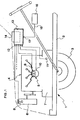
- the single figure represents a very simplified embodiment of a device making it possible to implement the method which has just been described above.
- This figure very schematically represents a vehicle 1 comprising a chassis 2, mounted on wheels 3, as well as a combustion engine 4, on which appear the ignition control means 5, the coolant reservoir 6 as well as that of the lubrication fluid
- the device more particularly comprises a plurality of sensors, in particular a sensor 8 of the temperature of the coolant, a sensor 9 of the electrical intensity of ignition control, a sensor 10 of the timing of the ignition advance. , and a sensor 11 of the pressure of the lubrication fluid.
- All the outputs of these sensors 8 to 11 are connected to the input 12 of a permanent memory 13 comprising a control input 17 for storing in memory.
- This input 17 is connected to the output 15 of a control means 16 which can be a clock delivering periodic signals, but, as said previously, advantageously, an odometer.
- This permanent memory 13 optionally includes output means 14 which allow the information recorded periodically to be taken from this memory or even the medium to be taken out, on which this information has been recorded, in order to transport it to a place where the information that it contains could be more conveniently analyzed.
- each sensor delivers a continuous signal representative of the state of the element to be tested and monitored.
- the signals emitted by these sensors are constantly compared with reference values which are representative, at least possibly over a certain range, of the signals that the sensors should emit when the elements they test are in correct or functioning states.
- this comparison detects a determined difference between the signal delivered by at least one sensor and its reference value, it then commands the recording of this fault signal, possibly even of all the other signals emitted by the sensors.
- the time interval will therefore be determined by at least the failures detected by a sensor. It is quite obvious that these recordings will be carried out over a fairly long period, and each time that a sensor will be delivered a signal corresponding to a fault or a failure of one of the elements of the engine, the recording of the data will be ordered in order to be stored, at least temporarily, so that it can be analyzed and studied later.
- an acceptable failure rate can be determined.
- the number of failures is totaled and memorized, and, after a certain number of kilometers traveled by the vehicle, this number is compared with an acceptable rate of reference failures. In this case, two solutions may appear.
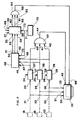
- FIG. 2 represents an embodiment of a device making it possible to implement the method which has just been described above.
- three sensors 8, 9, 10 deliver at their outputs signals which are sent respectively by links 21, 22, 23 respectively to the inputs 24, 25, 26 of three comparators 27, 28, 29 and to the three entries 30, 31, 32 of a memory 33.
- the three comparators 27,28,29 each have at least one input 34,35,36 to which signals representative of a correct value of a state of the element with which the sensors which deliver signals respectively can be applied on the links 21,22,23.
- the outputs 37, 38, 39 respectively of the comparators 27, 28, 29 are connected for example to three inputs 40, 41, 42 of a logic gate 43 of the OR type.
- the output 44 of this logic gate 43 is connected
- a memory storage recording command 33 which can be of any type, magnetic, optical, etc.
- the outputs 37, 38, 39 of the comparators 27, 28, 29 are connected to the inputs 46, 47, 48 of a multi-totalizer 49 making it possible to total the number of pulses which will be emitted at the outputs of the three comparators previously mentioned.
- This totalizer 49 is a totalizer of the type making it possible to add the number of signals which are received on these inputs 46,47,48 and to keep this in memory.
- the totalization outputs 50,51,52 are respectively connected to the inputs 53,54,55 of a multi-comparator 56 receiving on its comparison inputs 57,58,59 reference signals representing predetermined totalization values.
- the outputs 60, 61, 62 of this multi-comparator 56 are connected to the inputs 63 of a second logic gate 64 of the OR type, the output 65 of which is connected to a control input 66 of the memory 33.
- This logic gate 64 can deliver at its output at least one signal which can take two states, these two states applied to the input 66 allows, either to carry out a definitive recording of the previously memorized signals, sent on the inputs 30, 31, 32 , or to erase and reset this memory.
- the device finally comprises, in addition, in this embodiment, an odometer 70 whose output 71 is connected, on the one hand, to a comparison control input 72 of the comparator 56, and to an input 73 for control of transfer and reset of the multi-totalizer 49.
- the sensors continuously deliver signals which are sent on the links 21,22,23 and therefore cons applied to the inputs of the three comparators 27,28,29, as well as to the inputs 30,31,32 of memory 33.
- one of the comparators When one of the comparators detects an anomaly of at least one of the signals, one of these delivers at its output a signal which will, on the one hand, be counted unitarily in the multi-totalizer 49, and, d on the other hand, sent through the logic gate OR to the temporary memory command input 45, and, therefore, the signals from the sensors, when these faults have been detected, will be temporarily stored in memory 33.
- This process is repeated as many times as failures are detected, each failure being totaled in the multi-totalizer 49.
- the odometer 72 delivers at its output 71, when the car has traveled a certain number of kilometers, an order signal which will be applied both to the totalizer 49 to transfer all the numbers totaled therein to the comparator 56 and for that these signals are then compared
- an order signal will be sent to at least one of the outputs 60,61,62 which, through logic gate 64, will command final storage.
- the logic gate delivers a signal which, according to its state, applied to the input 66 of the memory 33, commands the erasure of this and its reset. In fact, this condition is interpreted as showing that the failures that have been detected are random and not significant in determining a potential poor condition of the motor vehicle engine.
- the comparator 56 delivers on at least one of its inputs a signal which constitutes a confirmation of the prerecorded information. Because these are then considered to be significant of a potential poor state of the engine. These can then be analyzed, interpreted and studied in a static location, possibly even by comparison with other complementary tests that can be performed there.
- sensors associated with the secondary winding of the ignition coil of the engine there may be mentioned sensors associated with the secondary winding of the ignition coil of the engine, an engine speed sensor, a point of advance sensor at the ignition in comparison for example with a sensor of the angular position of the crankshaft, a sensor of the depression of the engine on the level for example of the carburetor, etc.
- the methods and devices described above make it possible to rationally exploit the result of static and dynamic tests by minimizing to improve the diagnostics of motor vehicles, and by minimizing their downtime while increasing the safety of these vehicles since faults will be detected as soon as they appear and, therefore, accidents which would be the consequences of these faults can thus be avoided.
Landscapes
- Engineering & Computer Science (AREA)
- Chemical & Material Sciences (AREA)
- Combustion & Propulsion (AREA)
- Mechanical Engineering (AREA)
- General Engineering & Computer Science (AREA)
- Physics & Mathematics (AREA)
- General Physics & Mathematics (AREA)
- Time Recorders, Dirve Recorders, Access Control (AREA)
Applications Claiming Priority (2)
| Application Number | Priority Date | Filing Date | Title |
|---|---|---|---|
| FR8114848 | 1981-07-30 | ||
| FR8114848A FR2510756A1 (fr) | 1981-07-30 | 1981-07-30 | Procede et dispositif pour controler l'etat d'un vehicule automobile |
Publications (1)
| Publication Number | Publication Date |
|---|---|
| EP0071523A1 true EP0071523A1 (fr) | 1983-02-09 |
Family
ID=9261014
Family Applications (1)
| Application Number | Title | Priority Date | Filing Date |
|---|---|---|---|
| EP82401361A Withdrawn EP0071523A1 (fr) | 1981-07-30 | 1982-07-22 | Procédé et dispositif pour contrôler l'état d'un véhicule automobile |
Country Status (2)
| Country | Link |
|---|---|
| EP (1) | EP0071523A1 (xx) |
| FR (1) | FR2510756A1 (xx) |
Cited By (6)
| Publication number | Priority date | Publication date | Assignee | Title |
|---|---|---|---|---|
| EP0309346A1 (fr) * | 1987-09-25 | 1989-03-29 | Applications Electroniques Techniques Avancees "A.E.T.A." | Système de surveillance de paramètres d'un véhicule motorisé, notamment du moteur de ce véhicule |
| FR2640559A1 (fr) * | 1988-12-20 | 1990-06-22 | Renault | Systeme de support de donnees pour vehicule |
| FR2673244A1 (fr) * | 1991-02-21 | 1992-08-28 | Jeoffroy Jean Pierre | Dispositif et procede de controle du circuit de refroidissement des moteurs a combustion interne. |
| EP0629773A1 (de) * | 1993-06-18 | 1994-12-21 | Bayerische Motoren Werke Aktiengesellschaft | Diagnoseverfahren für Kraftfahrzeuge zum Überprüfen elektronisch gesteuerter Systeme |
| KR101125493B1 (ko) * | 2007-10-03 | 2012-03-20 | 퀄컴 인코포레이티드 | 이중 경로 전류 증폭기 |
| CN112983644A (zh) * | 2021-04-16 | 2021-06-18 | 杭州科技职业技术学院 | 一种基于神经网络的发动机故障诊断装置 |
Citations (3)
| Publication number | Priority date | Publication date | Assignee | Title |
|---|---|---|---|---|
| GB1298627A (en) * | 1970-03-20 | 1972-12-06 | Vdo Schindling | An operational monitoring system for aircraft |
| US4093939A (en) * | 1976-02-18 | 1978-06-06 | Transputer (Proprietary) Limited | Accessory for a vehicle for monitoring its operation and that of its drive means |
| US4246566A (en) * | 1978-05-09 | 1981-01-20 | Nippondenso Co., Ltd. | Malfunction diagnosing apparatus for electronic control system for vehicles |
-
1981
- 1981-07-30 FR FR8114848A patent/FR2510756A1/fr active Granted
-
1982
- 1982-07-22 EP EP82401361A patent/EP0071523A1/fr not_active Withdrawn
Patent Citations (3)
| Publication number | Priority date | Publication date | Assignee | Title |
|---|---|---|---|---|
| GB1298627A (en) * | 1970-03-20 | 1972-12-06 | Vdo Schindling | An operational monitoring system for aircraft |
| US4093939A (en) * | 1976-02-18 | 1978-06-06 | Transputer (Proprietary) Limited | Accessory for a vehicle for monitoring its operation and that of its drive means |
| US4246566A (en) * | 1978-05-09 | 1981-01-20 | Nippondenso Co., Ltd. | Malfunction diagnosing apparatus for electronic control system for vehicles |
Non-Patent Citations (1)
| Title |
|---|
| SCHIP EN WERF, vol.42, janvier 1975, Rotterdam (NL) * |
Cited By (9)
| Publication number | Priority date | Publication date | Assignee | Title |
|---|---|---|---|---|
| EP0309346A1 (fr) * | 1987-09-25 | 1989-03-29 | Applications Electroniques Techniques Avancees "A.E.T.A." | Système de surveillance de paramètres d'un véhicule motorisé, notamment du moteur de ce véhicule |
| FR2621122A1 (fr) * | 1987-09-25 | 1989-03-31 | Applic Electro Tech Avance | Systeme de surveillance de parametres d'un vehicule motorise, notamment du moteur de ce vehicule |
| FR2640559A1 (fr) * | 1988-12-20 | 1990-06-22 | Renault | Systeme de support de donnees pour vehicule |
| EP0378945A1 (fr) * | 1988-12-20 | 1990-07-25 | Regie Nationale Des Usines Renault | Système de support de données pour véhicule |
| FR2673244A1 (fr) * | 1991-02-21 | 1992-08-28 | Jeoffroy Jean Pierre | Dispositif et procede de controle du circuit de refroidissement des moteurs a combustion interne. |
| EP0629773A1 (de) * | 1993-06-18 | 1994-12-21 | Bayerische Motoren Werke Aktiengesellschaft | Diagnoseverfahren für Kraftfahrzeuge zum Überprüfen elektronisch gesteuerter Systeme |
| KR101125493B1 (ko) * | 2007-10-03 | 2012-03-20 | 퀄컴 인코포레이티드 | 이중 경로 전류 증폭기 |
| CN112983644A (zh) * | 2021-04-16 | 2021-06-18 | 杭州科技职业技术学院 | 一种基于神经网络的发动机故障诊断装置 |
| CN112983644B (zh) * | 2021-04-16 | 2022-04-19 | 杭州科技职业技术学院 | 一种基于神经网络的发动机故障诊断装置 |
Also Published As
| Publication number | Publication date |
|---|---|
| FR2510756B1 (xx) | 1983-12-30 |
| FR2510756A1 (fr) | 1983-02-04 |
Similar Documents
| Publication | Publication Date | Title |
|---|---|---|
| FR2774421A1 (fr) | Systeme de gestion du fonctionnement d'un filtre a particules associe a un moteur diesel notamment de vehicule automobile | |
| FR2601777A1 (fr) | Procede et dispositif d'essai du systeme de freinage d'un vehicule automobile | |
| FR2800190A1 (fr) | Procede et systeme pour l'autodiagnostic d'une voiture | |
| EP2307249A2 (fr) | Procede et systeme de diagnostic de l'etat de fonctionnement d'un systeme de demarrage assiste d'un vehicule automobile | |
| EP0071523A1 (fr) | Procédé et dispositif pour contrôler l'état d'un véhicule automobile | |
| EP1832493B1 (fr) | Système et procédé de vérification de l'intégrité d'un train | |
| FR3056002B1 (fr) | Procede d’analyse de donnees de composants de vehicules | |
| EP1316693A1 (fr) | Procéde et dispositif de diagnostic de l'état de fonctionnement d'une ligne d'échappement d'un moteur à combustion interne | |
| WO2001081885A1 (fr) | Procede et installation pour detecter et localiser une source de bruits et vibrations | |
| FR2745755A1 (fr) | Procede d'exploitation des mesures de pression et de temperature dans un systeme de surveillance de pneumatiques | |
| EP2419891B1 (fr) | Procede et dispositif d'identification et de reperage d'un evenement survenant sur un site d'un objet fixe ou mobile | |
| FR3071607A1 (fr) | Procede de determination de la frequence et de la phase instantanees d'un signal periodique | |
| FR3091613A1 (fr) | Procédé de maintenance automatique d’un véhicule autonome | |
| WO2022012837A1 (fr) | Procede et systeme de maintenance predictive | |
| FR2712106A1 (fr) | Dispositif d'enregistrement du type destiné à être placé sur un véhicule automobile routier. | |
| WO2021115764A1 (fr) | Consolidation d'une information de géolocalisation d'un véhicule | |
| FR3100647A1 (fr) | Procede et dispositif de gestion locative de vehicules | |
| EP0742656B2 (fr) | Procédé et systeme pour la sécurisation de la transmission de données entre un capteur et un enregistreur | |
| EP1163496A1 (fr) | Dispositif de detection de l'apport en carburant dans un reservoir d'un vehicule automobile | |
| FR2798645A1 (fr) | Systeme de determination de la quantite de carburant rajoutee dans un reservoir de vehicule automobile | |
| FR2949865A1 (fr) | Autodiagnostic de calculateurs mecatroniques | |
| EP2310647B1 (fr) | Procede de diagnostic des defaillances d'un filtre d'une ligne d'echappement des gaz d'un moteur a combustion interne | |
| EP0298888B1 (fr) | Procédé de saisie et lecture de données pour l'analyse de la conduite d'un véhicule routier | |
| EP2312137A2 (fr) | Procédé de diagnostic d'une anomalie dans une ligne d'échappement d'un moteur a combustion équipé d'un filtre a particules | |
| FR3128486A1 (fr) | Méthode de régénération conditionnelle d’un filtre à particules et dispositif de mise en œuvre |
Legal Events
| Date | Code | Title | Description |
|---|---|---|---|
| PUAI | Public reference made under article 153(3) epc to a published international application that has entered the european phase |
Free format text: ORIGINAL CODE: 0009012 |
|
| AK | Designated contracting states |
Designated state(s): BE DE GB IT NL |
|
| 17P | Request for examination filed |
Effective date: 19830616 |
|
| STAA | Information on the status of an ep patent application or granted ep patent |
Free format text: STATUS: THE APPLICATION IS DEEMED TO BE WITHDRAWN |
|
| 18D | Application deemed to be withdrawn |
Effective date: 19851205 |
|
| RIN1 | Information on inventor provided before grant (corrected) |
Inventor name: BOTTIAU, PHILIPPE |