EP0071501A1 - Winkelmässig begrenzte Antriebskupplung, um an eine Antriebswelle ein Hilfssteuermittel in zwei Stellungen der Drehrichtung der Welle folgend, zu kuppeln - Google Patents
Winkelmässig begrenzte Antriebskupplung, um an eine Antriebswelle ein Hilfssteuermittel in zwei Stellungen der Drehrichtung der Welle folgend, zu kuppeln Download PDFInfo
- Publication number
- EP0071501A1 EP0071501A1 EP82401289A EP82401289A EP0071501A1 EP 0071501 A1 EP0071501 A1 EP 0071501A1 EP 82401289 A EP82401289 A EP 82401289A EP 82401289 A EP82401289 A EP 82401289A EP 0071501 A1 EP0071501 A1 EP 0071501A1
- Authority
- EP
- European Patent Office
- Prior art keywords
- shaft
- rotation
- control means
- drive shaft
- crown
- Prior art date
- Legal status (The legal status is an assumption and is not a legal conclusion. Google has not performed a legal analysis and makes no representation as to the accuracy of the status listed.)
- Granted
Links
Images
Classifications
-
- F—MECHANICAL ENGINEERING; LIGHTING; HEATING; WEAPONS; BLASTING
- F16—ENGINEERING ELEMENTS AND UNITS; GENERAL MEASURES FOR PRODUCING AND MAINTAINING EFFECTIVE FUNCTIONING OF MACHINES OR INSTALLATIONS; THERMAL INSULATION IN GENERAL
- F16D—COUPLINGS FOR TRANSMITTING ROTATION; CLUTCHES; BRAKES
- F16D41/00—Freewheels or freewheel clutches
- F16D41/06—Freewheels or freewheel clutches with intermediate wedging coupling members between an inner and an outer surface
- F16D41/08—Freewheels or freewheel clutches with intermediate wedging coupling members between an inner and an outer surface with provision for altering the freewheeling action
- F16D41/10—Freewheels or freewheel clutches with intermediate wedging coupling members between an inner and an outer surface with provision for altering the freewheeling action with self-actuated reversing
- F16D41/105—Freewheels or freewheel clutches with intermediate wedging coupling members between an inner and an outer surface with provision for altering the freewheeling action with self-actuated reversing the intermediate members being of circular cross-section, of only one size and wedging by rolling movement not having an axial component between inner and outer races, one of which is cylindrical
-
- F—MECHANICAL ENGINEERING; LIGHTING; HEATING; WEAPONS; BLASTING
- F16—ENGINEERING ELEMENTS AND UNITS; GENERAL MEASURES FOR PRODUCING AND MAINTAINING EFFECTIVE FUNCTIONING OF MACHINES OR INSTALLATIONS; THERMAL INSULATION IN GENERAL
- F16D—COUPLINGS FOR TRANSMITTING ROTATION; CLUTCHES; BRAKES
- F16D43/00—Automatic clutches
- F16D43/02—Automatic clutches actuated entirely mechanically
- F16D43/26—Automatic clutches actuated entirely mechanically acting at definite angular position or disengaging after consecutive definite number of rotations
-
- G—PHYSICS
- G01—MEASURING; TESTING
- G01P—MEASURING LINEAR OR ANGULAR SPEED, ACCELERATION, DECELERATION, OR SHOCK; INDICATING PRESENCE, ABSENCE, OR DIRECTION, OF MOVEMENT
- G01P13/00—Indicating or recording presence, absence, or direction, of movement
- G01P13/02—Indicating direction only, e.g. by weather vane
- G01P13/04—Indicating positive or negative direction of a linear movement or clockwise or anti-clockwise direction of a rotational movement
Definitions
- the invention relates to a clutch with limited angular drive, intended to couple, to a drive shaft of a means of action with two directions of rotation, an auxiliary control means with two positions and cooperating with the means of action. , each position of the control means defining a mode of cooperation in correspondence with a determined direction of rotation of the motor shaft, so that the rotation of the motor shaft in one direction results in the corresponding position of the means of ordered.
- French patent application No. 77 37510 filed by the Applicant on December 13, 1977, relates to an autonomous hydraulic control assembly, in particular for a movable jaw of a vice for fixing a part in precise position on a machine -tool, this set comprising a two-stage hydraulic pump, one stage for rapid advance and one stage for pressure build-up, an electric motor with two directions of rotation driving the pump, an adjustable pressure switch, a single-acting cylinder and a relief valve.
- the pump discharges into the cylinder which clamps the vice; the start of clamping of the part leads to an increase in pressure of the jack; the pressure reaching a certain value, the low pressure stage is short-circuited by the relief valve, while the high pressure stage perfect the tightening; then the engine is stopped or restarted to maintain the pressure, determined by the adjustable pressure switch, the jack.
- the reverse rotation of the motor opens a second relief valve, connected to the jack, so that the vice is loosened.
- the clutch according to the invention has been developed to fit into such an autonomous hydraulic assembly, to control the closing or opening of the relief valve. cylinder, according to the direction of rotation of the motor.
- the subject of the invention is a clutch with reliable limited angular drive, and for this purpose proposes a clutch with limited angular drive, intended to couple, to a drive shaft of a means of action with two directions of rotation, a means of auxiliary control with two positions and cooperating with the action means, each position of the control means defining a mode of cooperation corresponding to a determined direction of rotation of the motor shaft, so that the rotation of the shaft motor in one direction causes the corresponding control means to be put into position, clutch characterized in that it comprises a fixed block freely traversed by the motor shaft, a crown acting on said control means and pivotally mounted in the block coaxially with the drive shaft, two wedging means arranged in contact with the drive shaft in housings of the crown, these housings each connecting by a ramp, capable of cooperating with the adjacent wedge means, to a cylindrical arc coaxial with the shaft and defining therewith an annular segment space of radial thickness less than the thickness of the wedging means and a stop finger integral with the block and penetrating into
- this wedging means forces itself in a wedge between the shaft and the crown, causing the latter in solidarity with the shaft, until the wedging means comes into contact with the stop finger; at this time, the crown being in the first position, the wedging means is stopped suddenly, which releases the crown ramp, and consequently releases the motor shaft from the wedging means.
- a rotation of the shaft in the opposite direction requests the second wedging means against the adjacent ramp, and the crown is driven to the second position.
- the crown housings are provided with elastic means urging the respective wedging means towards the adjacent ramps, so that the clutch is frank at the start in rotation of the motor shaft.
- the wedging means consist of cylindrical rollers. These, in contact with the shaft, are rotated, this rotation having the effect, in one direction of engaging a rolling roller under the adjacent ramp, whereby the wedging is self-tightening, and in the other direction to release the roller from the ramp.
- the roller releases jamming between the shaft and the adjacent ramp is in rolling friction and not strictly slippery, and risks less wear and seizures.
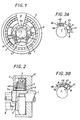
- the clutch comprises, around a motor shaft 1 with a rectified cylindrical bearing, a body 2 which is integral with the frame of a hydraulic assembly for the tightening of a machine tool vice.
- body 2 In body 2 is housed a rou ball bearing 3, in the inner ring bore from which is fitted a crown 4 with a flange 40.
- the front face of the flange 40 is of helical size to form a cam 9 for a push-button 7 of relief valve 8.
- the part central of the crown 4 comprises two housings 4l and 42 towards the shaft l, into which are inserted cylindrical rollers 6 and 6 ', bearing on the shaft 1.
- the housings 4l and 42 are connected to a cylindrical arc 45 which defines with the shaft 1 an annular segment space 46 of thickness less than the diameter of the rollers 6, 6 ', by two spiral ramps 43 and 44 respectively.
- a stop finger 5a at the end of a sector 5 fixed to the body, enters segment 46, without touching either the shaft 1 or the crown 4.
- the crown 4 is completed, between the housings 4l and 42, by a bridge 47 opposite the arc 45 o
- this bridge 47 are housed for pushers 8 and 8 ', equipped with springs to stress the rollers 6 and 6 ', respectively towards the ramps 43 and 44, the springs bearing on an arcuate plate 48.
- the clutch position shown in Figures 1 and 2 is essentially unstable. Indeed, the motor shaft 1 being supposed to turn anti-clockwise according to the arrow ( Figure 1), the rollers 6 and 6 'are urged, by contact with the shaft 1, to turn in clockwise. By reaction on the housing walls 41 and 42, the rollers 6 and 6 'would tend to rotate around the axis of the shaft 1, with a speed of rotation equal to half that of this shaft 1. It As a result, for the indicated direction of rotation, the roller 6 gets stuck between the ramp 43 and the shaft 1, while the roller 6 'emerges from the ramp 44.
- the crown 4 carries a helical ramp 9 on its front face.
- a pusher 7 of a relief valve, mentioned by the reference 8 bears on the ramp 9. It will be understood that, depending on whether the ramp 43 or the ramp 44 has come close to the stop finger 5a, the pusher 7 is advanced or pushed back, that is to say that the valve 8 is closed or open.
- This arrangement corresponds to the incorporation of the clutch into an autonomous hydraulic vice control assembly, the valve 8 being bypassed on the vice clamping cylinder, while the shaft 1 drives the high and low pumps. pressure; reversing the direction of rotation of the shaft 1, obtained electrically, causes the vice to be tightened or loosened.
Landscapes
- Engineering & Computer Science (AREA)
- General Engineering & Computer Science (AREA)
- Mechanical Engineering (AREA)
- Physics & Mathematics (AREA)
- General Physics & Mathematics (AREA)
- Mechanical Operated Clutches (AREA)
Priority Applications (1)
| Application Number | Priority Date | Filing Date | Title |
|---|---|---|---|
| AT82401289T ATE15713T1 (de) | 1981-07-23 | 1982-07-08 | Winkelmaessig begrenzte antriebskupplung, um an eine antriebswelle ein hilfssteuermittel in zwei stellungen der drehrichtung der welle folgend, zu kuppeln. |
Applications Claiming Priority (2)
| Application Number | Priority Date | Filing Date | Title |
|---|---|---|---|
| FR8114340A FR2510213A1 (fr) | 1981-07-23 | 1981-07-23 | Embrayage a entrainement angulaire limite, pour coupler a un arbre moteur un moyen de commande auxiliaire a deux positions suivant le sens de rotation de l'arbre |
| FR8114340 | 1981-07-23 |
Publications (2)
| Publication Number | Publication Date |
|---|---|
| EP0071501A1 true EP0071501A1 (de) | 1983-02-09 |
| EP0071501B1 EP0071501B1 (de) | 1985-09-18 |
Family
ID=9260795
Family Applications (1)
| Application Number | Title | Priority Date | Filing Date |
|---|---|---|---|
| EP82401289A Expired EP0071501B1 (de) | 1981-07-23 | 1982-07-08 | Winkelmässig begrenzte Antriebskupplung, um an eine Antriebswelle ein Hilfssteuermittel in zwei Stellungen der Drehrichtung der Welle folgend, zu kuppeln |
Country Status (4)
| Country | Link |
|---|---|
| EP (1) | EP0071501B1 (de) |
| AT (1) | ATE15713T1 (de) |
| DE (1) | DE3266387D1 (de) |
| FR (1) | FR2510213A1 (de) |
Cited By (4)
| Publication number | Priority date | Publication date | Assignee | Title |
|---|---|---|---|---|
| EP0370502A2 (de) * | 1988-11-24 | 1990-05-30 | P.A. Rentrop, Hubbert & Wagner Fahrzeugausstattungen GmbH & Co. KG | Verstellgetriebe für Kraftfahrzeugsitze mit Bremse |
| FR2648563A1 (fr) * | 1989-06-20 | 1990-12-21 | Crouzet Sa | Dispositif de determination du sens de deplacement d'un objet mobile |
| EP0497007A1 (de) * | 1991-02-01 | 1992-08-05 | Jörg Schwarzbich | Getriebe für die Übertragung einer Drehbewegung in beiden Drehsinnen |
| WO2000032440A1 (de) * | 1998-11-27 | 2000-06-08 | INA Wälzlager Schaeffler oHG | Stelleinrichtung, insbesondere zur verstellung eines kraftfahrzeugsitzes |
Families Citing this family (1)
| Publication number | Priority date | Publication date | Assignee | Title |
|---|---|---|---|---|
| CN114770171B (zh) * | 2022-05-31 | 2023-02-28 | 沭阳县职业教育中心 | 一种联轴器加工用高稳定性夹具 |
Citations (5)
| Publication number | Priority date | Publication date | Assignee | Title |
|---|---|---|---|---|
| US1529248A (en) * | 1924-03-26 | 1925-03-10 | W G Nagel Electric Company | Automatic clutch |
| DE882778C (de) * | 1950-06-30 | 1953-07-13 | Flender A F & Co | Freilaufkupplung, insbesondere fuer Schaltwerkswechselgetriebe |
| DE931379C (de) * | 1953-03-24 | 1955-08-08 | Licentia Gmbh | Drehrichtungsfuehler zur Anzeige der Drehrichtung umlaufender Wellen |
| GB747921A (en) * | 1952-11-24 | 1956-04-18 | Deuta Werke | Improvements in or relating to devices for indicating the number of revolutions or speed of a rotatable shaft |
| FR2411672A1 (fr) * | 1977-12-13 | 1979-07-13 | Mors Sa Electricite | Ensemble autonome de commande hydraulique notamment pour mors mobile d'un etau |
-
1981
- 1981-07-23 FR FR8114340A patent/FR2510213A1/fr active Granted
-
1982
- 1982-07-08 DE DE8282401289T patent/DE3266387D1/de not_active Expired
- 1982-07-08 EP EP82401289A patent/EP0071501B1/de not_active Expired
- 1982-07-08 AT AT82401289T patent/ATE15713T1/de not_active IP Right Cessation
Patent Citations (5)
| Publication number | Priority date | Publication date | Assignee | Title |
|---|---|---|---|---|
| US1529248A (en) * | 1924-03-26 | 1925-03-10 | W G Nagel Electric Company | Automatic clutch |
| DE882778C (de) * | 1950-06-30 | 1953-07-13 | Flender A F & Co | Freilaufkupplung, insbesondere fuer Schaltwerkswechselgetriebe |
| GB747921A (en) * | 1952-11-24 | 1956-04-18 | Deuta Werke | Improvements in or relating to devices for indicating the number of revolutions or speed of a rotatable shaft |
| DE931379C (de) * | 1953-03-24 | 1955-08-08 | Licentia Gmbh | Drehrichtungsfuehler zur Anzeige der Drehrichtung umlaufender Wellen |
| FR2411672A1 (fr) * | 1977-12-13 | 1979-07-13 | Mors Sa Electricite | Ensemble autonome de commande hydraulique notamment pour mors mobile d'un etau |
Cited By (7)
| Publication number | Priority date | Publication date | Assignee | Title |
|---|---|---|---|---|
| EP0370502A2 (de) * | 1988-11-24 | 1990-05-30 | P.A. Rentrop, Hubbert & Wagner Fahrzeugausstattungen GmbH & Co. KG | Verstellgetriebe für Kraftfahrzeugsitze mit Bremse |
| DE3839732A1 (de) * | 1988-11-24 | 1990-06-07 | Rentrop Hubbert & Wagner | Bremse fuer ein verstellgetriebe von kraftfahrzeugsitzen |
| EP0370502A3 (de) * | 1988-11-24 | 1991-10-30 | P.A. Rentrop, Hubbert & Wagner Fahrzeugausstattungen GmbH & Co. KG | Verstellgetriebe für Kraftfahrzeugsitze mit Bremse |
| FR2648563A1 (fr) * | 1989-06-20 | 1990-12-21 | Crouzet Sa | Dispositif de determination du sens de deplacement d'un objet mobile |
| EP0404657A1 (de) * | 1989-06-20 | 1990-12-27 | CROUZET Electrom˩nager | Vorrichtung zur Bestimmung der Bewegungsrichtung eines bewegbaren Gegenstandes |
| EP0497007A1 (de) * | 1991-02-01 | 1992-08-05 | Jörg Schwarzbich | Getriebe für die Übertragung einer Drehbewegung in beiden Drehsinnen |
| WO2000032440A1 (de) * | 1998-11-27 | 2000-06-08 | INA Wälzlager Schaeffler oHG | Stelleinrichtung, insbesondere zur verstellung eines kraftfahrzeugsitzes |
Also Published As
| Publication number | Publication date |
|---|---|
| ATE15713T1 (de) | 1985-10-15 |
| FR2510213B1 (de) | 1984-05-18 |
| EP0071501B1 (de) | 1985-09-18 |
| FR2510213A1 (fr) | 1983-01-28 |
| DE3266387D1 (en) | 1985-10-24 |
Similar Documents
| Publication | Publication Date | Title |
|---|---|---|
| FR2643838A1 (fr) | Dispositif de fixation rigide pour des pieces suspendues telles que poincons de presse-plieuse | |
| FR2543085A1 (fr) | Antivol de direction pour vehicule automobile | |
| EP0719389B1 (de) | Von einem elektromotor gesteuerte steuervorrichtung mit hydraulischem zylinder, insbesondere für eine kraftfahrzeugkupplung | |
| FR2593865A1 (fr) | Dispositif d'accouplement debrayable d'un moyeu a un arbre | |
| FR2834043A1 (fr) | Ensemble de serrage perfectionne et coupleur hydraulique le comportant | |
| EP0071501B1 (de) | Winkelmässig begrenzte Antriebskupplung, um an eine Antriebswelle ein Hilfssteuermittel in zwei Stellungen der Drehrichtung der Welle folgend, zu kuppeln | |
| EP0002632B1 (de) | Verschleissnachstellvorrichtung für Bremsen und Bremse versehen mit einer solchen Vorrichtung | |
| EP1996826B1 (de) | Losdrehsicherungsvorrichtung mit feder | |
| FR2888147A1 (fr) | Mecanisme d'arret et mecanisme d'ajustement de couple pour outil rotatif et outil rotatif comportant de tels mecanisme d'arret et mecanisme d'ajustement de couple | |
| WO1994009285A1 (fr) | Moteur de frein a encombrement reduit | |
| FR2655704A1 (fr) | Accessoire de sanitaire. | |
| FR2629380A1 (fr) | Dispositif d'indexation pour tours revolver et analogues | |
| EP0069032B1 (de) | Sicherheitsbremsvorrichtung, eingesetzt zwischen einer Antriebswelle und einem rotierenden Arbeitsteil | |
| EP2612049B1 (de) | Drehmomentübertragungsvorrichtung | |
| EP0786596A1 (de) | Peristaltische Pumpe | |
| EP1412651B1 (de) | Verbindungsvorrichtung für kupplungsmuffe | |
| FR2534724A1 (fr) | Mecanisme de liaison intermittente | |
| FR2944075A1 (fr) | Dispositif mecanique de transmission d'effort a seuil | |
| FR2596476A1 (fr) | Limiteur de couple a declenchement total a une valeur predeterminee du couple transmis | |
| FR2671995A1 (fr) | Dispositif pour l'usinage de la paroi ou du bord d'un trou perce a l'avance. | |
| FR2860027A1 (fr) | Ferme porte encastrable | |
| WO2010139081A1 (fr) | Dispositif d'embrayage, de freinage, de limitation de couple et de blocage mecanique | |
| WO2023031279A1 (fr) | Appareil de préparation des aliments à démarrage automatique | |
| BE529743A (de) | ||
| FR2956056A1 (fr) | Outil de vissage a arret mecanique |
Legal Events
| Date | Code | Title | Description |
|---|---|---|---|
| PUAI | Public reference made under article 153(3) epc to a published international application that has entered the european phase |
Free format text: ORIGINAL CODE: 0009012 |
|
| AK | Designated contracting states |
Designated state(s): AT BE CH DE GB IT LI LU NL SE |
|
| 17P | Request for examination filed |
Effective date: 19830603 |
|
| RAP1 | Party data changed (applicant data changed or rights of an application transferred) |
Owner name: MORS |
|
| GRAA | (expected) grant |
Free format text: ORIGINAL CODE: 0009210 |
|
| AK | Designated contracting states |
Designated state(s): AT BE CH DE GB IT LI LU NL SE |
|
| PG25 | Lapsed in a contracting state [announced via postgrant information from national office to epo] |
Ref country code: NL Effective date: 19850918 Ref country code: IT Free format text: LAPSE BECAUSE OF FAILURE TO SUBMIT A TRANSLATION OF THE DESCRIPTION OR TO PAY THE FEE WITHIN THE PRESCRIBED TIME-LIMIT;WARNING: LAPSES OF ITALIAN PATENTS WITH EFFECTIVE DATE BEFORE 2007 MAY HAVE OCCURRED AT ANY TIME BEFORE 2007. THE CORRECT EFFECTIVE DATE MAY BE DIFFERENT FROM THE ONE RECORDED. Effective date: 19850918 Ref country code: AT Effective date: 19850918 |
|
| REF | Corresponds to: |
Ref document number: 15713 Country of ref document: AT Date of ref document: 19851015 Kind code of ref document: T |
|
| PG25 | Lapsed in a contracting state [announced via postgrant information from national office to epo] |
Ref country code: SE Effective date: 19850930 |
|
| REF | Corresponds to: |
Ref document number: 3266387 Country of ref document: DE Date of ref document: 19851024 |
|
| NLV1 | Nl: lapsed or annulled due to failure to fulfill the requirements of art. 29p and 29m of the patents act | ||
| PLBE | No opposition filed within time limit |
Free format text: ORIGINAL CODE: 0009261 |
|
| STAA | Information on the status of an ep patent application or granted ep patent |
Free format text: STATUS: NO OPPOSITION FILED WITHIN TIME LIMIT |
|
| PG25 | Lapsed in a contracting state [announced via postgrant information from national office to epo] |
Ref country code: LU Free format text: LAPSE BECAUSE OF NON-PAYMENT OF DUE FEES Effective date: 19860731 Ref country code: LI Effective date: 19860731 Ref country code: CH Effective date: 19860731 Ref country code: BE Effective date: 19860731 |
|
| 26N | No opposition filed | ||
| BERE | Be: lapsed |
Owner name: MORS Effective date: 19860731 |
|
| REG | Reference to a national code |
Ref country code: CH Ref legal event code: PL |
|
| PG25 | Lapsed in a contracting state [announced via postgrant information from national office to epo] |
Ref country code: DE Effective date: 19870401 |
|
| GBPC | Gb: european patent ceased through non-payment of renewal fee | ||
| PG25 | Lapsed in a contracting state [announced via postgrant information from national office to epo] |
Ref country code: GB Effective date: 19881121 |