EP0071202A1 - Method and apparatus for optically inspecting a moving web of glass - Google Patents
Method and apparatus for optically inspecting a moving web of glass Download PDFInfo
- Publication number
- EP0071202A1 EP0071202A1 EP82106642A EP82106642A EP0071202A1 EP 0071202 A1 EP0071202 A1 EP 0071202A1 EP 82106642 A EP82106642 A EP 82106642A EP 82106642 A EP82106642 A EP 82106642A EP 0071202 A1 EP0071202 A1 EP 0071202A1
- Authority
- EP
- European Patent Office
- Prior art keywords
- glass
- web
- light
- edges
- defects
- Prior art date
- Legal status (The legal status is an assumption and is not a legal conclusion. Google has not performed a legal analysis and makes no representation as to the accuracy of the status listed.)
- Withdrawn
Links
- 239000011521 glass Substances 0.000 title claims abstract description 82
- 238000000034 method Methods 0.000 title claims abstract description 15
- 230000007547 defect Effects 0.000 claims abstract description 19
- 238000007689 inspection Methods 0.000 claims abstract description 12
- 230000033001 locomotion Effects 0.000 claims abstract description 11
- 230000003287 optical effect Effects 0.000 claims abstract description 6
- 230000005855 radiation Effects 0.000 claims abstract description 3
- 238000001816 cooling Methods 0.000 claims description 3
- 239000012080 ambient air Substances 0.000 claims description 2
- 230000000903 blocking effect Effects 0.000 claims 1
- 238000010276 construction Methods 0.000 abstract description 3
- 239000005329 float glass Substances 0.000 description 7
- 238000012545 processing Methods 0.000 description 7
- 230000006870 function Effects 0.000 description 4
- 238000004519 manufacturing process Methods 0.000 description 4
- 239000003570 air Substances 0.000 description 3
- 238000001514 detection method Methods 0.000 description 3
- 239000000463 material Substances 0.000 description 3
- XKRFYHLGVUSROY-UHFFFAOYSA-N Argon Chemical compound [Ar] XKRFYHLGVUSROY-UHFFFAOYSA-N 0.000 description 2
- 238000013459 approach Methods 0.000 description 2
- 239000000428 dust Substances 0.000 description 2
- 238000010438 heat treatment Methods 0.000 description 2
- 238000012986 modification Methods 0.000 description 2
- 230000004048 modification Effects 0.000 description 2
- 238000006748 scratching Methods 0.000 description 2
- 230000002393 scratching effect Effects 0.000 description 2
- 230000003595 spectral effect Effects 0.000 description 2
- 238000002834 transmittance Methods 0.000 description 2
- OKTJSMMVPCPJKN-UHFFFAOYSA-N Carbon Chemical compound [C] OKTJSMMVPCPJKN-UHFFFAOYSA-N 0.000 description 1
- 101000916532 Rattus norvegicus Zinc finger and BTB domain-containing protein 38 Proteins 0.000 description 1
- 230000005856 abnormality Effects 0.000 description 1
- 230000009102 absorption Effects 0.000 description 1
- 238000010521 absorption reaction Methods 0.000 description 1
- 229910052786 argon Inorganic materials 0.000 description 1
- 230000005540 biological transmission Effects 0.000 description 1
- 238000007664 blowing Methods 0.000 description 1
- UIZLQMLDSWKZGC-UHFFFAOYSA-N cadmium helium Chemical compound [He].[Cd] UIZLQMLDSWKZGC-UHFFFAOYSA-N 0.000 description 1
- 229910052799 carbon Inorganic materials 0.000 description 1
- 230000006735 deficit Effects 0.000 description 1
- 238000003708 edge detection Methods 0.000 description 1
- 238000001914 filtration Methods 0.000 description 1
- 239000005357 flat glass Substances 0.000 description 1
- 239000007789 gas Substances 0.000 description 1
- 239000001307 helium Substances 0.000 description 1
- 229910052734 helium Inorganic materials 0.000 description 1
- SWQJXJOGLNCZEY-UHFFFAOYSA-N helium atom Chemical compound [He] SWQJXJOGLNCZEY-UHFFFAOYSA-N 0.000 description 1
- 238000005286 illumination Methods 0.000 description 1
- 238000012544 monitoring process Methods 0.000 description 1
- 230000008447 perception Effects 0.000 description 1
- 230000004044 response Effects 0.000 description 1
- 150000003839 salts Chemical class 0.000 description 1
- 238000012549 training Methods 0.000 description 1
- 230000001960 triggered effect Effects 0.000 description 1
- 230000000007 visual effect Effects 0.000 description 1
- 238000011179 visual inspection Methods 0.000 description 1
- XLYOFNOQVPJJNP-UHFFFAOYSA-N water Substances O XLYOFNOQVPJJNP-UHFFFAOYSA-N 0.000 description 1
Images
Classifications
-
- G—PHYSICS
- G01—MEASURING; TESTING
- G01N—INVESTIGATING OR ANALYSING MATERIALS BY DETERMINING THEIR CHEMICAL OR PHYSICAL PROPERTIES
- G01N21/00—Investigating or analysing materials by the use of optical means, i.e. using sub-millimetre waves, infrared, visible or ultraviolet light
- G01N21/84—Systems specially adapted for particular applications
- G01N21/88—Investigating the presence of flaws or contamination
- G01N21/89—Investigating the presence of flaws or contamination in moving material, e.g. running paper or textiles
- G01N21/892—Investigating the presence of flaws or contamination in moving material, e.g. running paper or textiles characterised by the flaw, defect or object feature examined
- G01N21/896—Optical defects in or on transparent materials, e.g. distortion, surface flaws in conveyed flat sheet or rod
Definitions
- This invention relates to a method and apparatus for automatically optically inspecting a glass web, and more particularly to such a method and apparatus which utilizes internal reflection moving from defects in the web toward the edges and edge detecting the totally internally reflected light at the edges thereof.
- the many problems are the detection of bubbles in the glass which are caused by gases captured by the molten elements during the heating process. Such bubbles do not have time to emerge before the glass leaves the heating process.
- the bubbles vary in size from microns to several centimeters and their size and number vary with the thickness of the glass.
- Bubbles may be classified as filled bubbles or salt cakes which look like stones and occur infrequently; body bubbles which are small in diameter, relative to the thickness of the glass, which do not distort the glass and appear as small, spherical or eliptical lines and block transmitted light in the glass; or surface bubbles which tend to appear just below the surface of the glass, mostly on the lower surface in float glass and cause distortion in the glass and as an extreme case provide an open bubble when the bubble breaks on the surface.
- Bubbles vary greatly in shape from spherical to ellipsoidal with the larger bubbles tending to be more elongated as well as those which are generated in higher speed glass lines. The most important factors in determining the bubble shape are the operating characteristics of a particular float line fur manufacturing the glass.
- bubble detection is done visibly by inspectors with the glass being lit or illuminated from the top such that the defect casts a characteristic shadow on a white board under the glass web.
- glass inspectors can learn to identify certain kinds of flaws.
- the location must be marked with a colored crayon attached to the end of a long pointer.
- the accuracy depends on the experience of the inspector, the speed of the line and of course, the foibles of human perceptions and response.
- a further object of this invention is to provide a new and improved apparatus and method of optically inspecting a moving web of glass which eliminates the subjective nature of visual inspection.
- a further object of this invention is to provide a new and improved method and apparatus for optically inspecting a moving web of glass for defects which is fast, efficient, more accurate and less time-consuming than previously used visual methods.
- a method of automatically optically inspecting a moving web of glass in which the moving web of glass is scanned orthogonally with respect to the direction of movement with a light source. As the light source strikes a defect within the web, it is internally reflected in the glass and travels towards the edges where it is captured on the opposite ends of the glass web. The captured light emanating from the edges of the web caused by internal reflection due to defects in the glass, is detected for converting the light to electrical signals and the defects are determined in accordance with the characteristics of the electrical signals so generated.
- Apparatus for carrying out the aforesaid method including edge detection means which surround opposite sides of the web and prevent ambient light from entering the edge detectors.
- the edge detectors are also cooled and follow the vertical and horizontal motions of the web so as not to disturb the manufacture of the web.
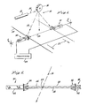
- a light inspection system referred to generally with the reference numeral 10, has a suitable light source such as a laser beam, zenon lamp, etc. generating a beam 14 which is scanned by a scanner 16 over a moving web of glass 20 which is being examined thereby.
- the scanner 16 may be a conventional, multiple faceted, mirrored surface polygon of a suitable number of facets.
- the scanner 16 may comprise any means which functions to rapidly scan a light source across the surface of the glass web 20, such as an oscillating mirror, rotating mirror or prism, or any other suitable deflection apparatus.
- the scanner 16 performs the function of scanning the light source repeatedly across the moving web of glass 20 which is moving in the direction shown by the arrows 22 which may be referred to as the machine direction or axis of web movement. As illustrated in Figure 1, the scanning light beam 14 traces a line 24 across the moving web of glass 20. Scanning in the orthogonal direction is automatically formed by the movement of the glass web 20.
- the scanning of the glass web 20 by the light beam 14 causes the beam 14 to be partially reflected from the top surface of the glass web 20 with a portion of the beam being refracted by the glass web 20 as well as being absorbed thereby.
- the light will impinge on the abnormality and be deflected thereby producing an angle of reflection which satisfies the critical angle and causes total internal reflection within the glass which travels towards the edges of the glass web 20.
- some of the totally internal reflected light is absorbed as it moves towards the edges.
- Figure 2 illustrates this phenomena with the scanning light beam 14 striking a bubble 25 totally internally reflecting the resulting beam 26 which by total internal reflection is trapped in the glass web.
- the beam 26 moves to the edges where it may be captured and detected.
- the intensity of the total reflected beam 26 appearing at the edge of the glass plate 20 is a function of the illumination wavelength, the distance between the edge and the bubble, and the initial intensity of the scanner beam 14.
- edge detectors In order to capture and detect the internally reflected beam 26, edge detectors, referred to generally with the reference numeral 30, are provided by flanking both edges of the moving glass web 20.
- the function of the edge detector is to capture the reflected light 26 that emerges from the edges of the glass web 20 on a float line without being disturbed by ambient or stray light due to dust or foreign matter on the glass surface, and further to convert such light into an electrical signal which may be utilized to identify and characterize the flaw which is present.
- a suitable light detector such as a photomultiplier tube 32 is utilized for converting the internally reflected light appearing at the edges of the web 20 into an electrical signal.
- Edge detector 30 includes a number of features due to the conditions which it must operate under including a warm glass web which may be dusty, wet and moving in all directions, as well as having varying amounts of ambient light which must be excluded and not measured.
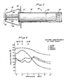
- the construction of the edge detector 30, as best seen in Figure 3, includes a mouth 34 that fits over the glass edge such that only the edges of the glass are seen by the detector or photomultiplier tube 32.
- the mouth has upper and lower jaws 36 and 38 with the jaws being movable in order to follow the glass web.
- the jaws are held by springs 40 mounted on a vertical rail 42.
- the detectors 30 may be moved manually in the horizontal direction because the horizontal movements are very slow. However, the horizontal movement may also be done mechanically.
- a preferable way of moving the edge detectors 30 along the web would be by providing glass edge sensors which operate pneumatic cylinders to follow the horizontal and vertical movements of the web.
- the mouth 34 is equipped with upper and lower brushes 46 and 48, respectively, which completely seal the mouth in a light tight condition without scratching or altering the glass product.
- the brushes 46 and 48 may be carbon filter or other resistant material mounted in a light labyrinth construction.
- the photomultiplier tube 32 has a noise characteristic proportional to temperature, and since the float glass and the ambient air are warm at the inspection site, typically between 40° and 60°, cooling of the tube becomes necessary. Accordingly, a fan 50 is provided for blowing air in the detector housing 52. By filtering the air inside, the detector housing can be kept dust free by creating an overpresssure in the air stream which also prevents water which is normally present on the web edges from condensing on the photomultiplier tube window.
- the source 10 which generates the beam 14 is scanned by the scanner 16 orthogonally across the glass web being inspected.
- the edge detectors 30 fit over the glass edge and capture the light which is internally reflected toward the edges of the glass web 20 due to defects occurring in the glass web which have been struck by the scanning light beam 14 and have been caused to be totally internally reflected to the edges of the glass web.
- the brushes 46 and 48 on the jaws 36 and 38 of the mouth 34 mechanically follow the movements or the motions of the web and follow the web without admitting ambient light thereto and without scratching or altering the product.
- the electrical signals which are generated by the detector 32 are applied to a processing circuit 55 from which flaws or defects may be characterized depending on their. location, size and type.
- the signals generated must exceed a predetermined amplitude which takes care of system anomalies and noise and indicates that a flaw exists and that a flaw signal rather than noise has triggered the output of the processing circuit 55.
- the signal processing techniques per se are considered conventional and accordingly are not discussed in detail. Reference may be made to U.S. 3,781,531; 3,900,265; 3,920,970; 3,898,469 and 3,980,891 which are assigned to the assignee of the present invention for information with respect to signal processing. The exact nature and type of processing used will depend on the characteristics of the material being inspected and the particular application to which the processing is employed.
- Figure 4 is a graph illustrating the spectral transmittance of float glass verses wavelength indicating the wavelength of a helium cadmium laser, an argon laser or a helium laser. Due to its properties, clear glass has a slightly green appearance which is readily visible in thick glass plates. Accordingly, clear glass transmits visible light almost independently of color with the best transmission for green being about 500 nanometers. When light hits a flat glass surface, about 8 percent of the light is reflected and about 2 percent is absorbed per centimeter. Accordingly, Figure 4 provides a relation between the absorptions for different wavelengths in clear and various colored glasses.- The type of source which is utilized will therefore depend to some extent on the type of float glass which is being examined.
- the edge detector system may be used by itself or it may be used in conjunction with a receiver which detects the reflected light off of the top surface of the glass and/or the light which is transmitted through the glass by placing the receiver on the underside and processing the radiation therefrom.
- a more fully automatic and reliable automatic optical inspection system provides a complete diagnostic tool for the examination of float glass.
- this method and approach to the inspection of glass provides a way of distinguishing between surface dirt and actual defects in surface and in the glass.
Landscapes
- Engineering & Computer Science (AREA)
- Textile Engineering (AREA)
- Physics & Mathematics (AREA)
- Health & Medical Sciences (AREA)
- Life Sciences & Earth Sciences (AREA)
- Chemical & Material Sciences (AREA)
- Analytical Chemistry (AREA)
- Biochemistry (AREA)
- General Health & Medical Sciences (AREA)
- General Physics & Mathematics (AREA)
- Immunology (AREA)
- Pathology (AREA)
- Investigating Materials By The Use Of Optical Means Adapted For Particular Applications (AREA)
Abstract
An automatic optical inspection of a moving web of glass for defects is provided by transversely scanning a moving web of glass (20) with a light beam (14) which is internally reflected within the glass and travels towards the edge of the glass when the scanning light beam (14) strikes defects within the web. The light leaving the edges of the glass as a result of internal reflection is captured on opposite edges of the web. The captured light is detected and converted to electrical signals which are utilized to determine whether defects are present in the web. An apparatus (10) is provided for the inspection method which includes edge detectors (30) having a mouthlike construction fitting over the edges of the web and collecting internally reflected radiation from the edges of the web, only, and applying it to photomultiplier tubes which are cooled. The edge detectors are enslaved mechanically so as to follow the movements of the web.
Description
- This invention relates to a method and apparatus for automatically optically inspecting a glass web, and more particularly to such a method and apparatus which utilizes internal reflection moving from defects in the web toward the edges and edge detecting the totally internally reflected light at the edges thereof.
- The imposition of stringent quality restrictions on the manufacture of float glass presents a serious inspection problem. The type of flaws, the number and where they are located within the glass web is a difficult task for human inspection. With insufficient product knowledge, it is difficult to determine what portion of the glass must be scrapped, which can be salvaged and how to prevent wasted time and materials in the manufacturing process.
- Among the many problems are the detection of bubbles in the glass which are caused by gases captured by the molten elements during the heating process. Such bubbles do not have time to emerge before the glass leaves the heating process. The bubbles vary in size from microns to several centimeters and their size and number vary with the thickness of the glass. Bubbles may be classified as filled bubbles or salt cakes which look like stones and occur infrequently; body bubbles which are small in diameter, relative to the thickness of the glass, which do not distort the glass and appear as small, spherical or eliptical lines and block transmitted light in the glass; or surface bubbles which tend to appear just below the surface of the glass, mostly on the lower surface in float glass and cause distortion in the glass and as an extreme case provide an open bubble when the bubble breaks on the surface.
- Bubbles vary greatly in shape from spherical to ellipsoidal with the larger bubbles tending to be more elongated as well as those which are generated in higher speed glass lines. The most important factors in determining the bubble shape are the operating characteristics of a particular float line fur manufacturing the glass.
- Traditionally bubble detection is done visibly by inspectors with the glass being lit or illuminated from the top such that the defect casts a characteristic shadow on a white board under the glass web. Through training and experience, glass inspectors can learn to identify certain kinds of flaws. When a flaw is identified, the location must be marked with a colored crayon attached to the end of a long pointer. However, a great deal of subjective judgment is involved, the accuracy depends on the experience of the inspector, the speed of the line and of course, the foibles of human perceptions and response.
- Accordingly, it is an object of this invention to provide a new and improved method and apparatus for automatically optically inspecting a moving web of glass for defects therein.
- A further object of this invention is to provide a new and improved apparatus and method of optically inspecting a moving web of glass which eliminates the subjective nature of visual inspection.
- A further object of this invention is to provide a new and improved method and apparatus for optically inspecting a moving web of glass for defects which is fast, efficient, more accurate and less time-consuming than previously used visual methods.
- In carrying out this invention, in one illustrative embodiment thereof, a method of automatically optically inspecting a moving web of glass is provided in which the moving web of glass is scanned orthogonally with respect to the direction of movement with a light source. As the light source strikes a defect within the web, it is internally reflected in the glass and travels towards the edges where it is captured on the opposite ends of the glass web. The captured light emanating from the edges of the web caused by internal reflection due to defects in the glass, is detected for converting the light to electrical signals and the defects are determined in accordance with the characteristics of the electrical signals so generated.
- Apparatus is provided for carrying out the aforesaid method including edge detection means which surround opposite sides of the web and prevent ambient light from entering the edge detectors. The edge detectors are also cooled and follow the vertical and horizontal motions of the web so as not to disturb the manufacture of the web.
- The invention, together with further objects, advantages, features and aspects thereof, will be more clearly understood from the following description taken in conjunction with the accompanying drawings:
- Figure 1 is a perspective view showing an illustrative embodiment of apparatus for automatically optically inspecting a moving web of glass in accordance with the present invention;
- Figure 2 is a cross-sectional view taken along line 2-2 of Figure 1;
- Figure 3 is a side elevational view of an edge detector assembly which may be utilized in the present invention; and
- Figure 4 is a graph illustrating the spectral transmittance of several types of float glass.
- Referring now to Figure 1, a light inspection system, referred to generally with the
reference numeral 10, has a suitable light source such as a laser beam, zenon lamp, etc. generating abeam 14 which is scanned by ascanner 16 over a moving web ofglass 20 which is being examined thereby. Thescanner 16 may be a conventional, multiple faceted, mirrored surface polygon of a suitable number of facets. However, it will be appreciated that thescanner 16 may comprise any means which functions to rapidly scan a light source across the surface of theglass web 20, such as an oscillating mirror, rotating mirror or prism, or any other suitable deflection apparatus. - The
scanner 16 performs the function of scanning the light source repeatedly across the moving web ofglass 20 which is moving in the direction shown by thearrows 22 which may be referred to as the machine direction or axis of web movement. As illustrated in Figure 1, thescanning light beam 14 traces aline 24 across the moving web ofglass 20. Scanning in the orthogonal direction is automatically formed by the movement of theglass web 20. - Under ordinary operating conditions, the scanning of the
glass web 20 by thelight beam 14 causes thebeam 14 to be partially reflected from the top surface of theglass web 20 with a portion of the beam being refracted by theglass web 20 as well as being absorbed thereby. On the other hand, if a bubble impairment or defect exists in the glass as it is scanned by thebeam 14, the light will impinge on the abnormality and be deflected thereby producing an angle of reflection which satisfies the critical angle and causes total internal reflection within the glass which travels towards the edges of theglass web 20. Of course, some of the totally internal reflected light is absorbed as it moves towards the edges. - Figure 2 illustrates this phenomena with the scanning
light beam 14 striking abubble 25 totally internally reflecting theresulting beam 26 which by total internal reflection is trapped in the glass web. Thebeam 26 moves to the edges where it may be captured and detected. The intensity of the totalreflected beam 26 appearing at the edge of theglass plate 20 is a function of the illumination wavelength, the distance between the edge and the bubble, and the initial intensity of thescanner beam 14. - In order to capture and detect the internally reflected
beam 26, edge detectors, referred to generally with thereference numeral 30, are provided by flanking both edges of themoving glass web 20. Of course, the function of the edge detector is to capture thereflected light 26 that emerges from the edges of theglass web 20 on a float line without being disturbed by ambient or stray light due to dust or foreign matter on the glass surface, and further to convert such light into an electrical signal which may be utilized to identify and characterize the flaw which is present. A suitable light detector such as a photomultiplier tube 32 is utilized for converting the internally reflected light appearing at the edges of theweb 20 into an electrical signal. -
Edge detector 30 includes a number of features due to the conditions which it must operate under including a warm glass web which may be dusty, wet and moving in all directions, as well as having varying amounts of ambient light which must be excluded and not measured. The construction of theedge detector 30, as best seen in Figure 3, includes amouth 34 that fits over the glass edge such that only the edges of the glass are seen by the detector or photomultiplier tube 32. The mouth has upper andlower jaws springs 40 mounted on avertical rail 42. Thedetectors 30 may be moved manually in the horizontal direction because the horizontal movements are very slow. However, the horizontal movement may also be done mechanically. A preferable way of moving theedge detectors 30 along the web would be by providing glass edge sensors which operate pneumatic cylinders to follow the horizontal and vertical movements of the web. - Since it is desired to exclude ambient light from the face of the photomultiplier tube 32, the
mouth 34 is equipped with upper andlower brushes 46 and 48, respectively, which completely seal the mouth in a light tight condition without scratching or altering the glass product. Thebrushes 46 and 48 may be carbon filter or other resistant material mounted in a light labyrinth construction. - Since the photomultiplier tube 32 has a noise characteristic proportional to temperature, and since the float glass and the ambient air are warm at the inspection site, typically between 40° and 60°, cooling of the tube becomes necessary. Accordingly, a
fan 50 is provided for blowing air in thedetector housing 52. By filtering the air inside, the detector housing can be kept dust free by creating an overpresssure in the air stream which also prevents water which is normally present on the web edges from condensing on the photomultiplier tube window. - In operation the
source 10 which generates thebeam 14 is scanned by thescanner 16 orthogonally across the glass web being inspected. Theedge detectors 30 fit over the glass edge and capture the light which is internally reflected toward the edges of theglass web 20 due to defects occurring in the glass web which have been struck by thescanning light beam 14 and have been caused to be totally internally reflected to the edges of the glass web. Thebrushes 46 and 48 on thejaws mouth 34 mechanically follow the movements or the motions of the web and follow the web without admitting ambient light thereto and without scratching or altering the product. As will be seen in Figure 1, the electrical signals which are generated by the detector 32 are applied to aprocessing circuit 55 from which flaws or defects may be characterized depending on their. location, size and type. Generally speaking, the signals generated must exceed a predetermined amplitude which takes care of system anomalies and noise and indicates that a flaw exists and that a flaw signal rather than noise has triggered the output of theprocessing circuit 55. The signal processing techniques per se are considered conventional and accordingly are not discussed in detail. Reference may be made to U.S. 3,781,531; 3,900,265; 3,920,970; 3,898,469 and 3,980,891 which are assigned to the assignee of the present invention for information with respect to signal processing. The exact nature and type of processing used will depend on the characteristics of the material being inspected and the particular application to which the processing is employed. - Figure 4 is a graph illustrating the spectral transmittance of float glass verses wavelength indicating the wavelength of a helium cadmium laser, an argon laser or a helium laser. Due to its properties, clear glass has a slightly green appearance which is readily visible in thick glass plates. Accordingly, clear glass transmits visible light almost independently of color with the best transmission for green being about 500 nanometers. When light hits a flat glass surface, about 8 percent of the light is reflected and about 2 percent is absorbed per centimeter. Accordingly, Figure 4 provides a relation between the absorptions for different wavelengths in clear and various colored glasses.- The type of source which is utilized will therefore depend to some extent on the type of float glass which is being examined.
- By utilizing total internal reflection and monitoring the light emanating from the edges caused by the flaws provides a tool which may be utilized in combination with others to form reliable detection on a very high percentage of glass defects. Thus, the edge detector system may be used by itself or it may be used in conjunction with a receiver which detects the reflected light off of the top surface of the glass and/or the light which is transmitted through the glass by placing the receiver on the underside and processing the radiation therefrom. By utilizing these combined approaches, a more fully automatic and reliable automatic optical inspection system provides a complete diagnostic tool for the examination of float glass. Furthermore, this method and approach to the inspection of glass provides a way of distinguishing between surface dirt and actual defects in surface and in the glass.
- Since other changes and modifications varied to fit particular operating requirements and environments will be apparent to those skilled in the art, the invention is not considered limited to the examples chosen for purpose of illustration, and covers all changes and modifications which do not constitute a departure from the true spirit and scope of this invention.
Claims (7)
1. A method of automatically optically inspecting a moving web of glass for defects, characterized by transversely scanning the moving web of glass with a light source, internally reflecting the scanning light source within the glass which travels toward the edges when it strikes defects within the web, capturing the light that leaves the glass on opposite edges of said glass web, detecting the captured light for converting the light to electrical signals, and determining whether defects are present in said glass web in accordance with the characteristics of said electrical signals.
2. The method according to claim 1, characterized by blocking ambient light from entering the edges of the glass web so that such ambient light is not captured with the internal reflected light.
3.- The method according to claim 1 or 2, characterized by tracking the horizontal and vertical motions of the glass web as the captured light is detected.
4. An automatic optical inspection system for inspecting a moving web of glass, characterized by a light source (14),scanning means (16) for scanning said light source orthogonally across said moving glass web, said light source beirginternally reflected within said glass web toward the edges thereof when said light source strikes a defect therein, and detector means (30) comprising collecting means (34) positioned on opposite edges of said glass web for capturing the light emerging from the edges of said glass web and applying the radiation so gathered to a signal generating means (32), said signal generating means being operable to generate electrical signals in accordance with the intensity of the light applied thereto.
5. The optical inspection system according to claim 4, characterized in that said collecting means includes a mouth (34) having movable jaws (36, 38) thereon which are adapted to be mounted on and conform generally with the configuration of the edges of said glass web.
6. The optical inspection system according to claim 5, characterized in that said jaws have brushes (46, 48) mounted thereon for eliminating ambient air from the edges of the glass web when the jaws of said mouth are mounted thereon.
7. The optical inspection system according to claim 4, 5, or 6, characterized in that at least one collecting means and signal generating means are mounted in a common housing (52) and cooling means (50) is provided in said housing for cooling said detector means.
Applications Claiming Priority (2)
| Application Number | Priority Date | Filing Date | Title |
|---|---|---|---|
| US288010 | 1981-07-29 | ||
| US06/288,010 US4401893A (en) | 1981-07-29 | 1981-07-29 | Method and apparatus for optically inspecting a moving web of glass |
Publications (1)
| Publication Number | Publication Date |
|---|---|
| EP0071202A1 true EP0071202A1 (en) | 1983-02-09 |
Family
ID=23105374
Family Applications (1)
| Application Number | Title | Priority Date | Filing Date |
|---|---|---|---|
| EP82106642A Withdrawn EP0071202A1 (en) | 1981-07-29 | 1982-07-23 | Method and apparatus for optically inspecting a moving web of glass |
Country Status (2)
| Country | Link |
|---|---|
| US (1) | US4401893A (en) |
| EP (1) | EP0071202A1 (en) |
Cited By (4)
| Publication number | Priority date | Publication date | Assignee | Title |
|---|---|---|---|---|
| GB2158940A (en) * | 1984-05-17 | 1985-11-20 | Zeiss Stiftung | Detecting defects in transparent materials |
| EP0336350A3 (en) * | 1988-04-06 | 1991-02-06 | Fraunhofer-Gesellschaft Zur Förderung Der Angewandten Forschung E.V. | Device for the optical inspection of moving surfaces |
| WO2001018532A1 (en) * | 1999-09-02 | 2001-03-15 | Resolve Engineering Pty Ltd | Detection of inclusions in glass |
| DE102005022271B3 (en) * | 2005-05-10 | 2006-08-17 | Schott Ag | Method for detecting bubbles or trapped matter in a glass body such as a glass tube during a continuous manufacturing process whereby images are detected of a surface of the glass body |
Families Citing this family (21)
| Publication number | Priority date | Publication date | Assignee | Title |
|---|---|---|---|---|
| DE3334357C2 (en) * | 1983-09-22 | 1986-04-10 | Erwin Sick Gmbh Optik-Elektronik, 7808 Waldkirch | Optical fault locator for railways |
| FR2563337B1 (en) * | 1984-04-19 | 1986-06-27 | Saint Gobain Rech | MEASUREMENT OF CONSTRAINTS IN FLEET GLASS |
| US4719061A (en) * | 1985-08-12 | 1988-01-12 | Essex Group, Inc. | System and method for in-process detection of contamination in electrical conductor insulation |
| IL85851A0 (en) * | 1988-03-24 | 1988-09-30 | Israel Atomic Energy Comm | Method and apparatus for detecting flaws in transparent bodies |
| FI81453C (en) * | 1988-06-22 | 1990-10-10 | Outokumpu Oy | ANALYSATORTAETNING. |
| US5517301A (en) * | 1993-07-27 | 1996-05-14 | Hughes Aircraft Company | Apparatus for characterizing an optic |
| JPH10221268A (en) * | 1997-02-05 | 1998-08-21 | Advantest Corp | Method and apparatus for detecting wafer surface condition |
| US6392683B1 (en) * | 1997-09-26 | 2002-05-21 | Sumitomo Heavy Industries, Ltd. | Method for making marks in a transparent material by using a laser |
| JP4018347B2 (en) * | 2001-04-13 | 2007-12-05 | 富士フイルム株式会社 | Surface inspection apparatus and surface inspection method |
| DE10221945C1 (en) | 2002-05-13 | 2003-07-31 | Schott Glas | Process for determining defects in continuously moved sheet of transparent material, especially wide thin window glass sheet, involves coupling monochromatic light beam in the sheet via transparent liquid between light source and sheet |
| DE10316707B4 (en) * | 2003-04-04 | 2006-04-27 | Schott Ag | Method and device for detecting defects in transparent material |
| DE10351254A1 (en) * | 2003-11-03 | 2005-06-02 | Adc Automotive Distance Control Systems Gmbh | Apparatus for detecting soiling on a translucent cover in front of an optical unit |
| US7511807B2 (en) * | 2003-12-30 | 2009-03-31 | Agency For Science, Technology And Research | Method and apparatus for detection of inclusion in glass |
| KR101442290B1 (en) * | 2007-01-11 | 2014-09-19 | 쓰리엠 이노베이티브 프로퍼티즈 컴파니 | Web longitudinal position sensor |
| US7800749B2 (en) * | 2007-05-31 | 2010-09-21 | Corning Incorporated | Inspection technique for transparent substrates |
| KR101493115B1 (en) * | 2007-06-19 | 2015-02-12 | 쓰리엠 이노베이티브 프로퍼티즈 컴파니 | Systems and methods for indicating the position of a web |
| BRPI0811664A2 (en) * | 2007-06-19 | 2015-02-10 | 3M Innovative Properties Co | "TOTAL INTERNAL REFLECTION DISPLACEMENT SCALE" |
| EP2162705A4 (en) * | 2007-06-19 | 2014-02-19 | 3M Innovative Properties Co | Systems and methods for fabricating displacement scales |
| SG172349A1 (en) | 2008-12-29 | 2011-07-28 | 3M Innovative Properties Co | Phase-locked web position signal using web fiducials |
| WO2010077719A2 (en) | 2008-12-30 | 2010-07-08 | 3M Innovative Properties Company | Apparatus and method for making fiducials on a substrate |
| CN109297975A (en) * | 2018-08-16 | 2019-02-01 | 奇酷互联网络科技(深圳)有限公司 | Mobile terminal and detection method, storage device |
Citations (3)
| Publication number | Priority date | Publication date | Assignee | Title |
|---|---|---|---|---|
| GB898828A (en) * | 1959-06-26 | 1962-06-14 | Gen Electric Co Ltd | Improvements in or relating to the examination of transparent sheet material |
| DE2327381A1 (en) * | 1972-05-30 | 1973-12-13 | Saint Gobain | PROCEDURE FOR DETERMINING DEFECTS IN FLAT GLASS |
| DE2527403A1 (en) * | 1975-06-19 | 1977-02-24 | Sick Optik Elektronik Erwin | Inspecting translucent synthetic, esp. glass fibre reinforced pipes - by scanning with light rays and measuring reflected intensity |
Family Cites Families (2)
| Publication number | Priority date | Publication date | Assignee | Title |
|---|---|---|---|---|
| GB1315654A (en) * | 1969-05-21 | 1973-05-02 | Pilkington Brothers Ltd | Detection of faults in transparent material using lasers |
| US3859537A (en) * | 1973-10-15 | 1975-01-07 | Du Pont | Inspection system for web materials |
-
1981
- 1981-07-29 US US06/288,010 patent/US4401893A/en not_active Expired - Fee Related
-
1982
- 1982-07-23 EP EP82106642A patent/EP0071202A1/en not_active Withdrawn
Patent Citations (3)
| Publication number | Priority date | Publication date | Assignee | Title |
|---|---|---|---|---|
| GB898828A (en) * | 1959-06-26 | 1962-06-14 | Gen Electric Co Ltd | Improvements in or relating to the examination of transparent sheet material |
| DE2327381A1 (en) * | 1972-05-30 | 1973-12-13 | Saint Gobain | PROCEDURE FOR DETERMINING DEFECTS IN FLAT GLASS |
| DE2527403A1 (en) * | 1975-06-19 | 1977-02-24 | Sick Optik Elektronik Erwin | Inspecting translucent synthetic, esp. glass fibre reinforced pipes - by scanning with light rays and measuring reflected intensity |
Cited By (5)
| Publication number | Priority date | Publication date | Assignee | Title |
|---|---|---|---|---|
| GB2158940A (en) * | 1984-05-17 | 1985-11-20 | Zeiss Stiftung | Detecting defects in transparent materials |
| EP0336350A3 (en) * | 1988-04-06 | 1991-02-06 | Fraunhofer-Gesellschaft Zur Förderung Der Angewandten Forschung E.V. | Device for the optical inspection of moving surfaces |
| WO2001018532A1 (en) * | 1999-09-02 | 2001-03-15 | Resolve Engineering Pty Ltd | Detection of inclusions in glass |
| DE102005022271B3 (en) * | 2005-05-10 | 2006-08-17 | Schott Ag | Method for detecting bubbles or trapped matter in a glass body such as a glass tube during a continuous manufacturing process whereby images are detected of a surface of the glass body |
| EP1722215A1 (en) | 2005-05-10 | 2006-11-15 | Schott AG | Method and apparatus to detect bubbles in a glass object and for the manufacture of glass objects |
Also Published As
| Publication number | Publication date |
|---|---|
| US4401893A (en) | 1983-08-30 |
Similar Documents
| Publication | Publication Date | Title |
|---|---|---|
| US4401893A (en) | Method and apparatus for optically inspecting a moving web of glass | |
| KR100756254B1 (en) | Dark View Inspection System for Transparent Media | |
| US3988068A (en) | Method and apparatus for detecting cosmetic defects in opthalmic lenses | |
| US5355213A (en) | Inspection system for detecting surface flaws | |
| US4223346A (en) | Automatic defect detecting inspection apparatus | |
| US5389794A (en) | Surface pit and mound detection and discrimination system and method | |
| CA2252308C (en) | Glass inspection system | |
| EP0174939B1 (en) | Panel surface flaw inspection | |
| KR850000308B1 (en) | How to detect particles on the material surface | |
| US4681442A (en) | Method for surface testing | |
| US3761186A (en) | Apparatus for optically inspecting the condition of a surface having known variations in the condition | |
| CN100371677C (en) | Substrate surface detection method and equipment | |
| US4483615A (en) | Method and apparatus for detecting checks in glass tubes | |
| PL172759B1 (en) | Method of and apparatus for inspecting transparent materials | |
| JP4177556B2 (en) | Method and apparatus for measuring optical quality of plate glass and other translucent materials and detecting defects | |
| WO1999051971A1 (en) | Method and apparatus for the automatic inspection of optically transmissive planar objects | |
| JPH08278257A (en) | Moving-object inspecting method | |
| US5122672A (en) | Surface quality analyzer apparatus and method | |
| US5086232A (en) | Methods of and apparatus for inspecting surfaces for defects | |
| US4570074A (en) | Flying spot scanner system | |
| KR101039686B1 (en) | Method and apparatus for detecting defects of continuously manufactured and moving object transparent plates | |
| JPH06294749A (en) | Flaw inspection method for plat glass | |
| US3361025A (en) | Method and apparatus of detecting flaws in transparent bodies | |
| US20070008522A1 (en) | Glazing inspection | |
| GB2195178A (en) | Glass object inspection |
Legal Events
| Date | Code | Title | Description |
|---|---|---|---|
| PUAI | Public reference made under article 153(3) epc to a published international application that has entered the european phase |
Free format text: ORIGINAL CODE: 0009012 |
|
| AK | Designated contracting states |
Designated state(s): BE DE FR GB IT |
|
| 17P | Request for examination filed |
Effective date: 19830808 |
|
| STAA | Information on the status of an ep patent application or granted ep patent |
Free format text: STATUS: THE APPLICATION IS DEEMED TO BE WITHDRAWN |
|
| 18D | Application deemed to be withdrawn |
Effective date: 19850608 |
|
| RIN1 | Information on inventor provided before grant (corrected) |
Inventor name: DEHUYSSER, ANDRE |