EP0070768B1 - Collier porte-repères pour conducteurs électriques - Google Patents
Collier porte-repères pour conducteurs électriques Download PDFInfo
- Publication number
- EP0070768B1 EP0070768B1 EP19820401319 EP82401319A EP0070768B1 EP 0070768 B1 EP0070768 B1 EP 0070768B1 EP 19820401319 EP19820401319 EP 19820401319 EP 82401319 A EP82401319 A EP 82401319A EP 0070768 B1 EP0070768 B1 EP 0070768B1
- Authority
- EP
- European Patent Office
- Prior art keywords
- strip
- aperture
- marks
- supporting collar
- width
- Prior art date
- Legal status (The legal status is an assumption and is not a legal conclusion. Google has not performed a legal analysis and makes no representation as to the accuracy of the status listed.)
- Expired
Links
- 239000004020 conductor Substances 0.000 title claims description 24
- 210000002105 tongue Anatomy 0.000 description 21
- 239000003550 marker Substances 0.000 description 11
- 238000002372 labelling Methods 0.000 description 3
- 239000000463 material Substances 0.000 description 3
- 210000003323 beak Anatomy 0.000 description 2
- 230000000903 blocking effect Effects 0.000 description 2
- 239000004952 Polyamide Substances 0.000 description 1
- 238000004870 electrical engineering Methods 0.000 description 1
- 238000010616 electrical installation Methods 0.000 description 1
- 238000004519 manufacturing process Methods 0.000 description 1
- 238000005259 measurement Methods 0.000 description 1
- 238000000465 moulding Methods 0.000 description 1
- 239000004033 plastic Substances 0.000 description 1
- 229920002647 polyamide Polymers 0.000 description 1
- 230000000750 progressive effect Effects 0.000 description 1
- 230000000717 retained effect Effects 0.000 description 1
Images


Classifications
-
- H—ELECTRICITY
- H01—ELECTRIC ELEMENTS
- H01B—CABLES; CONDUCTORS; INSULATORS; SELECTION OF MATERIALS FOR THEIR CONDUCTIVE, INSULATING OR DIELECTRIC PROPERTIES
- H01B7/00—Insulated conductors or cables characterised by their form
- H01B7/36—Insulated conductors or cables characterised by their form with distinguishing or length marks
- H01B7/368—Insulated conductors or cables characterised by their form with distinguishing or length marks being a sleeve, ferrule, tag, clip, label or short length strip
-
- G—PHYSICS
- G09—EDUCATION; CRYPTOGRAPHY; DISPLAY; ADVERTISING; SEALS
- G09F—DISPLAYING; ADVERTISING; SIGNS; LABELS OR NAME-PLATES; SEALS
- G09F3/00—Labels, tag tickets, or similar identification or indication means; Seals; Postage or like stamps
- G09F3/08—Fastening or securing by means not forming part of the material of the label itself
- G09F3/14—Fastening or securing by means not forming part of the material of the label itself by strings, straps, chains, or wires
Definitions
- the invention relates to a marker carrier collar for electrical conductors comprising a flexible and deformable tongue able to be wound and fixed either around a conductor or around a bundle of conductors and means capable of receiving reference marks from identification of the conductor or of the bundle of conductors, the tongue having on the one hand a first end in which is disposed an opening provided with hooking means and on the other hand a second end capable of engaging in this opening so as to bringing a central region of the tongue in cooperation with the fastening members by a unidirectional sliding.
- Such collars are particularly used in electrical engineering to identify either single conductors, in particular of large cross-section, or bundles of multiple conductors, the nature, function, origin or destination of which must be perfectly defined. Incidentally, these collars can also be used to secure the electrical conductor (s) against a fixed or mobile element of an electrical installation.
- patent AU-B-434824 describes a labeling collar making it possible to obtain a progressive throttling of the object to be labeled by means of a cord with annular bulges cooperating with blocking means provided at one end of said cord.
- This labeling collar further comprises a labeling ear which extends perpendicular to that of the object to be labeled.
- this collar is not suitable, because of its conformation and its size in a plane perpendicular to the direction of the labeled object, and is inapplicable for the electronics or automation engineer wishing to locate the inputs and outputs of '' devices whose size is increasingly reduced.
- the invention proposes to remedy the drawbacks mentioned above and aims to provide a marker carrier collar having a very wide range of use; moreover, the marker carrier collar according to the invention aims to facilitate the reading of the markers.
- a marker carrier collar for electrical conductors comprising a flexible and deformable tongue capable of being wound and fixed around at least one conductor and means capable of receiving identification markers, this tongue having on the one hand a first end in which is disposed an opening provided with hooking means and on the other hand a second end capable of engaging in this opening so as to bring a central region of the tongue in cooperation with the attachment means by a unidirectional sliding.
- this marker carrier collar is characterized in that the tongue is molded in one piece with at least one lateral extension which extends along a direction XX 'parallel to that of the electrical conductor to be located and substantially perpendicular to the longitudinal direction YY 'of the tongue, this extension being connected by a root to the end of the tongue having the opening and being shaped to receive and hold reference-bearing rings.
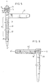
- a marker collar 1 visible in FIG. 1 comprises a flexible and deformable tongue 2 having a first end 3 provided with an opening 4 and a second opposite end 5 capable of engaging in the opening 4. This second end has a tapered shape 6 which facilitates this engagement.
- a straight outer surface 12 of a tooth is directed towards the opening 4, while an inclined outer surface 13 of a tooth is directed towards the second end.
- the opening 4 which has a width a close to the width b of the tongue and a height h close to the thickness e of the intermediate region 14 of the tongue, has a spout 15 having a width n close to the width m d 'a tooth, the latter being less than the width b of the tongue.
- An inclined ramp 16 can be arranged on the interior region of the opening opposite the spout to facilitate engagement of the second end.
- the engagement of the tongue in the opening can be carried out in a single direction F and the cooperation between this beak and these teeth in opposite directions ensures that the tightening is maintained as the we operate by placing the tab around a conductor or a bundle of conductors.
- the spout 15 is preferably placed in the opening 4 on the side of the tongue.
- a lateral extension 17 is associated with the tongue, integrating therewith as shown in FIGS. 1, 5, 6 and 7.
- a root 18 of this extension is located in the vicinity of the opening in a region 19.
- a root 18 ′ of extension 17 ′ can be located in a region 20 placed opposite the opening 4.
- the general direction XX ′ of this extension being substantially perpendicular to YY ′.
- the lateral extension 17 respectively 17 ′ has at its free end 21 bevelled surfaces such as 22 so as to facilitate the introduction in the direction G on this extension of marker carrier rings such as 23 see fig. 1 and 2, the particular sign of this ring being here represented by the letter R.
- a stop notch 24 limits the beveled surface 22 to prevent the loss of the ring or rings which will be threaded on the extension, while the surface of the latter may have in section a domed shape 25 so that the rings are retained by friction.
- a second extension 26 similar to the first extension 17 is attached to the tongue in the axis of the latter, which increases the capacity for handling marker carrier rings and avoids the use of a single extension of great length, which would be bulky and could not be shortened by cutting to the length strictly necessary due to the presence of the catch.
- the signs or markers R are preferably visible on a side C opposite to the face 7 carrying the teeth 10; this measure facilitates the orientation of the collar by rotation around the conductor due to the presence against the latter of a practically smooth surface, and avoids placing the blocking means, or spout, described above in a region deformable opening 4.
- This marker carrier ring is advantageously made by molding a plastic material from the family of polyamides, and can also be used to fix one or more conductors against a support.
Landscapes
- Physics & Mathematics (AREA)
- General Physics & Mathematics (AREA)
- Engineering & Computer Science (AREA)
- Theoretical Computer Science (AREA)
- Clamps And Clips (AREA)
- Adornments (AREA)
Applications Claiming Priority (2)
| Application Number | Priority Date | Filing Date | Title |
|---|---|---|---|
| FR8114117 | 1981-07-16 | ||
| FR8114117A FR2509918A1 (fr) | 1981-07-16 | 1981-07-16 | Collier porte-reperes pour conducteurs electriques |
Publications (2)
| Publication Number | Publication Date |
|---|---|
| EP0070768A1 EP0070768A1 (fr) | 1983-01-26 |
| EP0070768B1 true EP0070768B1 (fr) | 1985-07-03 |
Family
ID=9260686
Family Applications (1)
| Application Number | Title | Priority Date | Filing Date |
|---|---|---|---|
| EP19820401319 Expired EP0070768B1 (fr) | 1981-07-16 | 1982-07-13 | Collier porte-repères pour conducteurs électriques |
Country Status (3)
| Country | Link |
|---|---|
| EP (1) | EP0070768B1 (enExample) |
| DE (1) | DE3264554D1 (enExample) |
| FR (1) | FR2509918A1 (enExample) |
Families Citing this family (3)
| Publication number | Priority date | Publication date | Assignee | Title |
|---|---|---|---|---|
| DE3200178A1 (de) * | 1982-01-07 | 1983-07-14 | Friedrich Lütze Elektro GmbH, 7056 Weinstadt | Kennzeichnungsvorrichtung fuer eine elektrische leitung |
| DE4031172C2 (de) * | 1989-10-06 | 1994-08-11 | Horst Fraemcke | Markierungsvorrichtung |
| US5042181A (en) * | 1990-01-17 | 1991-08-27 | Thomas & Betts Corporation | Cable tie identification tag |
Family Cites Families (4)
| Publication number | Priority date | Publication date | Assignee | Title |
|---|---|---|---|---|
| CH364539A (fr) * | 1959-10-21 | 1962-09-30 | Electrique Comp Gle Entreprise | Dispositif pour le repérage d'un conducteur électrique |
| AU434824B2 (en) * | 1969-08-06 | 1973-04-12 | All-plastic seal | |
| FR2477330A1 (fr) * | 1980-02-29 | 1981-09-04 | Telemecanique Electrique | Embout d'extremite de cable electrique equipe d'un porte-repere amovible |
| FR2477305A1 (fr) * | 1980-02-29 | 1981-09-04 | Sterling Electr Sa | Element de reperage pour fils electriques, outil et support de mise en place |
-
1981
- 1981-07-16 FR FR8114117A patent/FR2509918A1/fr active Granted
-
1982
- 1982-07-13 DE DE8282401319T patent/DE3264554D1/de not_active Expired
- 1982-07-13 EP EP19820401319 patent/EP0070768B1/fr not_active Expired
Also Published As
| Publication number | Publication date |
|---|---|
| FR2509918B1 (enExample) | 1985-04-19 |
| FR2509918A1 (fr) | 1983-01-21 |
| DE3264554D1 (en) | 1985-08-08 |
| EP0070768A1 (fr) | 1983-01-26 |
Similar Documents
| Publication | Publication Date | Title |
|---|---|---|
| FR2714707A1 (fr) | Attache réglable. | |
| FR2745612A1 (fr) | Systeme de pince de retenue | |
| FR2781936A1 (fr) | Chemin de cable | |
| EP0070768B1 (fr) | Collier porte-repères pour conducteurs électriques | |
| CA1161509A (fr) | Embout d'extremite de cable electrique equipe d'un porte-repere amovible | |
| FR2458624A1 (fr) | Piece d'extremite, de raccordement ou de liaison pour elements souples tels que cables, fils ou autres elements | |
| EP0035460B1 (fr) | Elément de repérage pour fils électriques | |
| EP0254309B1 (fr) | Dispositif de maintien multiple notamment pour des faisceaux de fils dans un central téléphonique | |
| EP0710752B1 (fr) | Elément de protection pour noeuds ou joints d'échafaudages | |
| FR2589207A1 (fr) | Roulement avec bague de roulement divisee | |
| WO2007147973A1 (fr) | Etiquette auriculaire d’identification pour animal | |
| EP2134163B1 (fr) | Perfectionnement pour identifiant d'animaux | |
| EP1059135A1 (fr) | Dispositif de chanfreinage et de marquage pour tube. | |
| FR2587147A1 (fr) | Outil de pose formant magasion pour reperes, en particulier pour reperes de cablage | |
| FR2470276A1 (fr) | Collier de serrage | |
| FR3094582A1 (fr) | Pince auto-serrante pour câblage | |
| FR2524031A1 (fr) | Perfectionnements aux dispositifs d'ancrage destines a etre enfonces dans le sol | |
| FR2787168A1 (fr) | Dispositif de fixation d'une gaine sur un support sensiblement plan | |
| FR2704381A1 (fr) | Dispositif de repérage pour conducteur électrique. | |
| EP0545837A1 (fr) | Dispositif portant des repères pour marquer des conducteurs, et son procédé de fabrication | |
| FR2460615A1 (fr) | Marque a oreille pour l'identification des bovins | |
| EP0683342A1 (fr) | Collier de fixation d'éléments allongés quelconques | |
| FR2683922A1 (fr) | Dispositif de reperage de cables ou conduits electriques. | |
| FR2564078A1 (fr) | Dispositif enrouleur-derouleur de fil, notamment d'un fil de peche | |
| FR2548870A1 (fr) | Support prevu pour le maintien d'un element a l'aide d'un moyen tel qu'un fil de fer, applicable notamment en arboriculture |
Legal Events
| Date | Code | Title | Description |
|---|---|---|---|
| PUAI | Public reference made under article 153(3) epc to a published international application that has entered the european phase |
Free format text: ORIGINAL CODE: 0009012 |
|
| 17P | Request for examination filed |
Effective date: 19820715 |
|
| AK | Designated contracting states |
Designated state(s): BE DE GB IT |
|
| ITF | It: translation for a ep patent filed | ||
| GRAA | (expected) grant |
Free format text: ORIGINAL CODE: 0009210 |
|
| AK | Designated contracting states |
Designated state(s): BE DE GB IT |
|
| REF | Corresponds to: |
Ref document number: 3264554 Country of ref document: DE Date of ref document: 19850808 |
|
| PLBI | Opposition filed |
Free format text: ORIGINAL CODE: 0009260 |
|
| 26 | Opposition filed |
Opponent name: SIEMENS AKTIENGESELLSCHAFT, BERLIN UND MUENCHEN Effective date: 19860312 |
|
| PLBN | Opposition rejected |
Free format text: ORIGINAL CODE: 0009273 |
|
| STAA | Information on the status of an ep patent application or granted ep patent |
Free format text: STATUS: OPPOSITION REJECTED |
|
| 27O | Opposition rejected |
Effective date: 19881020 |
|
| ITTA | It: last paid annual fee | ||
| PGFP | Annual fee paid to national office [announced via postgrant information from national office to epo] |
Ref country code: DE Payment date: 20000623 Year of fee payment: 19 |
|
| PGFP | Annual fee paid to national office [announced via postgrant information from national office to epo] |
Ref country code: GB Payment date: 20000707 Year of fee payment: 19 |
|
| PGFP | Annual fee paid to national office [announced via postgrant information from national office to epo] |
Ref country code: BE Payment date: 20000801 Year of fee payment: 19 |
|
| PG25 | Lapsed in a contracting state [announced via postgrant information from national office to epo] |
Ref country code: GB Free format text: LAPSE BECAUSE OF NON-PAYMENT OF DUE FEES Effective date: 20010713 |
|
| PG25 | Lapsed in a contracting state [announced via postgrant information from national office to epo] |
Ref country code: DE Free format text: LAPSE BECAUSE OF NON-PAYMENT OF DUE FEES Effective date: 20010731 Ref country code: BE Free format text: LAPSE BECAUSE OF NON-PAYMENT OF DUE FEES Effective date: 20010731 |
|
| BERE | Be: lapsed |
Owner name: LA TELEMECANIQUE ELECTRIQUE Effective date: 20010731 |
|
| GBPC | Gb: european patent ceased through non-payment of renewal fee |
Effective date: 20010713 |