EP0070260A2 - Axialfluss-Dresch- und Trennvorrichtungseinheit für Mähdrescher - Google Patents
Axialfluss-Dresch- und Trennvorrichtungseinheit für Mähdrescher Download PDFInfo
- Publication number
- EP0070260A2 EP0070260A2 EP82830178A EP82830178A EP0070260A2 EP 0070260 A2 EP0070260 A2 EP 0070260A2 EP 82830178 A EP82830178 A EP 82830178A EP 82830178 A EP82830178 A EP 82830178A EP 0070260 A2 EP0070260 A2 EP 0070260A2
- Authority
- EP
- European Patent Office
- Prior art keywords
- separator
- thresher
- casing
- cylinder
- unit
- Prior art date
- Legal status (The legal status is an assumption and is not a legal conclusion. Google has not performed a legal analysis and makes no representation as to the accuracy of the status listed.)
- Granted
Links
- 241001124569 Lycaenidae Species 0.000 title claims abstract description 6
- 238000004140 cleaning Methods 0.000 claims abstract description 17
- 239000000463 material Substances 0.000 claims abstract description 12
- 241000251169 Alopias vulpinus Species 0.000 description 5
- 230000005540 biological transmission Effects 0.000 description 1
- 239000002184 metal Substances 0.000 description 1
- 230000032258 transport Effects 0.000 description 1
Images

Classifications
-
- A—HUMAN NECESSITIES
- A01—AGRICULTURE; FORESTRY; ANIMAL HUSBANDRY; HUNTING; TRAPPING; FISHING
- A01F—PROCESSING OF HARVESTED PRODUCE; HAY OR STRAW PRESSES; DEVICES FOR STORING AGRICULTURAL OR HORTICULTURAL PRODUCE
- A01F7/00—Threshing apparatus
- A01F7/02—Threshing apparatus with rotating tools
- A01F7/06—Threshing apparatus with rotating tools with axles in line with the feeding direction ; Axial threshing machines
- A01F7/065—Threshing apparatus with rotating tools with axles in line with the feeding direction ; Axial threshing machines with cage sweep mechanisms
-
- A—HUMAN NECESSITIES
- A01—AGRICULTURE; FORESTRY; ANIMAL HUSBANDRY; HUNTING; TRAPPING; FISHING
- A01F—PROCESSING OF HARVESTED PRODUCE; HAY OR STRAW PRESSES; DEVICES FOR STORING AGRICULTURAL OR HORTICULTURAL PRODUCE
- A01F12/00—Parts or details of threshing apparatus
- A01F12/18—Threshing devices
Definitions
- the present invention relates to combine harvesters provided with axial-flow thresher-separator units.
- the invention concerns an axial-flow thresher-separator unit for combine harvesters, of the type comprising a thresher-separator cylinder and a separator casing in the form of a perforated tubular body surrounding the thresher-separator cylinder, and cleaning means comprising at least one cleaning member movable adjacent an upper part of the outer surface of the separator casing for preventing part of the separated material from accumulating in this zone.
- the harvested product follows a helical path around the thresher-separator cylinder, moving axially from one end thereof to the other. This allows the efficiency of the threshing and separating action to be improved relative to conventional thresher units in which the harvested product passes through a space between the thresher concave and the threshing cylinder moving in a direction perpendicular to the axis of the latter.
- Thresher-separator units of the axial-flow type have the disadvantage that, when the upper part of the separator casing is also perforated, part of the separated material may accumulate in the apertures of this upper part and clog this zone.
- an axial-flow thresher-separator unit which is provided with a cleaning member movable adjacent the outer surface of the separator casing following a path parallel to the axis of the thresher-separator cylinder, reciprocating from one end of this casing to the other.
- a cleaning member movable adjacent the outer surface of the separator casing following a path parallel to the axis of the thresher-separator cylinder, reciprocating from one end of this casing to the other.
- the present invention has as its subject an axial-flow thresher-separator unit of the aforesaid type, the main characteristic of which lies in the fact that the cleaning member is arranged to move on the outer surface of the separator casing, following a path which is substantially in the form of an arc of a circle lying in a plane substantially perpendicular to the axis of the thresher-separator cylinder.
- thresher-separator unit may also be applied to combine harvesters of a type different from that illustrated.
- the combine harvester includes wheels 2 (of which only the front ones are visible in the Figure) on which is mounted a fixed structure 3.
- the combine harvester 1 carries a cutting table 4 including a feed auger 5 of a known type.
- a thresher-separator unit 6 of the axial-flow type which is illustrated in perspective in Figure 2.
- the thresher-separator unit 6 comprises a thresher-separator cylinder 7 arranged transversely of the longitudinal axis of the harvester, a thresher concave 8 constituted by a concave grille which surrounds a lower part of the thresher-separator cylinder 7, and a separator casing 9 constituted by a perforated tubular body surrounding that part of the cylinder 7 not covered by the thresher concave 8.
- the separator casing 9 has an opening 11 (see Figure 1) at one end for feeding the harvested product through into the space between the cylinder 7 and the casing 9.
- the thresher-separator unit 6 includes a fixed support structure 16 (see Figure 2) defining a mouth 11a for conveying the product in correspondence with the opening 11 in the separator casing 9.
- a transverse feed roller 10 is located in the mouth 11a for receiving the product from the auger 5 and conveying it to the unit 6.
- the product fed into the separator casing 9 follows a helical path around the thresher-separator cylinder 7, moving towards the opposite end of the cylinder.
- the material which does not pass through the apertures of the separator casing is discharged directly onto the ground so as to form a windrow alongside the harvester.
- the remaining material separated during the movement of the product around the thresher cylinder falls beneath the separator casing 9 and is deposited on a collecting floor 12 (see Figure 1) located below the thresher-separator unit 6.
- the combine harvester is provided with an auger 13 located in correspondence with the collecting floor 12 for conveying the grain towards the loading end of a bladed elevator 14 which transports the grain, with the aid of a second elevator 15, to the cleaning members (not illustrated) located in the rear part of the harvester.
- a bladed elevator 14 which transports the grain
- a second elevator to the cleaning members (not illustrated) located in the rear part of the harvester.
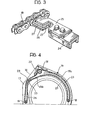
- Figure 2 illustrates the thresher-separator unit 6 in perspective without the thresher-separator cylinder 7.
- the fixed support structure 16 of the unit 6 includes three ribs 17 (one of which is illustrated in Figure 4) located at the ends and the centre of the separator casing 9, respectively.
- the ribs 17, which are constituted by sheet metal panels disposed in planes perpendicular to the axis of the thresher-separator cylinder, rotatably support pulleys 18 (see Figure 4) with which two pairs of endless chains 19 are engaged.
- each chain 19 engages three pulleys 18 of which one is disposed higher up and two lower down.
- the upper pulley is connected for rotation with the corresponding pulleys of the other chains 19 by means of a shaft 20 (see Figure 2) which is rotated by means of a conventional transmission (not illustrated) through a torque limiter 21.
- each chain 19 is further provided with a chain tensioning device 22 and guide members 23 arranged so that each chain 19 has an internal section 19a and an external section 19b lying in an arc of a circle adjacent the upper part of the outer surface of the casing 9.
- the four chains 19 support, in pairs, a pair of rods 24 arranged to act as cleaning members for preventing part of the separated material from accumulating in the upper part of the separator casing 9.
- Each rod 24 has its two ends fixed to the corresponding chains 19.
- each rod 24 has a C-section with its concave side facing the surface of the casing, and is provided at each end with a plate 25 which is fixed to the rod 14 by means of screws and on which an apertured body 26 is welded, being mounted on extensions of two pins 27 of the chain 19.
- the fixed structure 16 of the thresher-separator unit further includes a collecting floor 28 located adjacent the part of the separator casing 9 in correspondence with which is located the inlet opening 11.
- This collecting floor 28 is intended to receive the product separated by the initial part of the separator casing and prevent this product from falling into the inlet opening 11.
- a screw conveyor 29 is located in correspondence with the collecting floor 28 to carry the material deposited on the collecting floor 28 towards that part of the unit 6 located beyond the opening 11. Having reached this zone, the material falls onto a guide wall 12a which i directs the material towards the collecting floor 12.
- the shaft of the screw 29 is extended beyond the opening 11 and is provided on this extension with radial blades 29a which facilitate the discharge of the product onto the wall 12a.
- each rod 24 moves adjacent the outer surface of the casing 9 through an angle of about 200 0 removing any D material which tends to accumulate in this zone.
- each rod moves along the section 19a in an anti-clockwise sense relative to the casing 9 and along the section 19b in a clockwise sense. Not withstanding that the section 19b is further from 5 the surface of the casing 9 than the section 19a, the cleaning action of the rod 24 is found to be efficient even when the rod moves along the section 19b, as has been shown by tests carried out by the Applicants.
Landscapes
- Life Sciences & Earth Sciences (AREA)
- Environmental Sciences (AREA)
- Threshing Machine Elements (AREA)
Applications Claiming Priority (2)
| Application Number | Priority Date | Filing Date | Title |
|---|---|---|---|
| IT6796881 | 1981-07-13 | ||
| IT67968/81A IT1144300B (it) | 1981-07-13 | 1981-07-13 | Gruppo battitore separatore a flusso assiale per macchine mietitrebbiatrici |
Publications (3)
| Publication Number | Publication Date |
|---|---|
| EP0070260A2 true EP0070260A2 (de) | 1983-01-19 |
| EP0070260A3 EP0070260A3 (en) | 1983-05-18 |
| EP0070260B1 EP0070260B1 (de) | 1985-08-21 |
Family
ID=11306809
Family Applications (1)
| Application Number | Title | Priority Date | Filing Date |
|---|---|---|---|
| EP82830178A Expired EP0070260B1 (de) | 1981-07-13 | 1982-06-16 | Axialfluss-Dresch- und Trennvorrichtungseinheit für Mähdrescher |
Country Status (3)
| Country | Link |
|---|---|
| EP (1) | EP0070260B1 (de) |
| DE (1) | DE3265607D1 (de) |
| IT (1) | IT1144300B (de) |
Cited By (2)
| Publication number | Priority date | Publication date | Assignee | Title |
|---|---|---|---|---|
| EP0223749A1 (de) * | 1985-11-19 | 1987-05-27 | FIATGEOTECH - TECNOLOGIE PER LA TERRA S.p.A. | Axialfluss-Dresch- und -Trennvorrichtungseinheit für Mähdrescher |
| FR2615350A1 (fr) * | 1987-05-23 | 1988-11-25 | Claas Ohg | Moissonneuse-batteuse automotrice |
Citations (3)
| Publication number | Priority date | Publication date | Assignee | Title |
|---|---|---|---|---|
| FR2302679A1 (fr) * | 1975-03-01 | 1976-10-01 | Claas Maschf Gmbh Geb | Dispositif pour nettoyer la corbeille de battage d'une moissonneuse-batteuse |
| DE2812655A1 (de) * | 1977-03-23 | 1978-09-28 | Allis Chalmers | Agitatorvorrichtung fuer eine axialfluss-trommel |
| US4154250A (en) * | 1978-03-03 | 1979-05-15 | Allis-Chalmers Corporation | Drive mechanism and support arrangement for agitator of axial flow threshing cylinder |
-
1981
- 1981-07-13 IT IT67968/81A patent/IT1144300B/it active
-
1982
- 1982-06-16 EP EP82830178A patent/EP0070260B1/de not_active Expired
- 1982-06-16 DE DE8282830178T patent/DE3265607D1/de not_active Expired
Patent Citations (3)
| Publication number | Priority date | Publication date | Assignee | Title |
|---|---|---|---|---|
| FR2302679A1 (fr) * | 1975-03-01 | 1976-10-01 | Claas Maschf Gmbh Geb | Dispositif pour nettoyer la corbeille de battage d'une moissonneuse-batteuse |
| DE2812655A1 (de) * | 1977-03-23 | 1978-09-28 | Allis Chalmers | Agitatorvorrichtung fuer eine axialfluss-trommel |
| US4154250A (en) * | 1978-03-03 | 1979-05-15 | Allis-Chalmers Corporation | Drive mechanism and support arrangement for agitator of axial flow threshing cylinder |
Cited By (3)
| Publication number | Priority date | Publication date | Assignee | Title |
|---|---|---|---|---|
| EP0223749A1 (de) * | 1985-11-19 | 1987-05-27 | FIATGEOTECH - TECNOLOGIE PER LA TERRA S.p.A. | Axialfluss-Dresch- und -Trennvorrichtungseinheit für Mähdrescher |
| FR2615350A1 (fr) * | 1987-05-23 | 1988-11-25 | Claas Ohg | Moissonneuse-batteuse automotrice |
| BE1004191A3 (fr) * | 1987-05-23 | 1992-10-13 | Claas Ohg | Moissonneuse-batteuse automotrice. |
Also Published As
| Publication number | Publication date |
|---|---|
| DE3265607D1 (en) | 1985-09-26 |
| EP0070260A3 (en) | 1983-05-18 |
| IT1144300B (it) | 1986-10-29 |
| EP0070260B1 (de) | 1985-08-21 |
| IT8167968A0 (it) | 1981-07-13 |
Similar Documents
| Publication | Publication Date | Title |
|---|---|---|
| CA1040045A (en) | Rethresher | |
| US3945178A (en) | Crop harvesting and threshing machines | |
| US5497605A (en) | Header and feeder for a grain combine | |
| CA2019449C (en) | Improved crop processor | |
| US3742686A (en) | Axial flow combine harvester | |
| US6350197B1 (en) | Offset auger feed for a combine clean grain elevator | |
| US3669122A (en) | Axial flow combine with a rotary discharge | |
| DE3042731C2 (de) | ||
| EP2055178B1 (de) | System zum erneuten Dreschen für einen Mähdrescher | |
| US4148323A (en) | Swept back impeller blade for axial flow rotor | |
| GB1399602A (en) | Harvesting machines | |
| DE2000553B2 (de) | Mähdrescher mit axialem Arbeitsfluß | |
| US4484587A (en) | Axial-flow thresher-separator unit for combine harvesters | |
| US2927694A (en) | Rotary separator for harvester threshers | |
| EP2064940A1 (de) | Ausputz-Drescher-Ablenker | |
| CA1040043A (en) | Rotor for a combine | |
| US4497327A (en) | Combine harvester with angled axial thresher | |
| EP0070260B1 (de) | Axialfluss-Dresch- und Trennvorrichtungseinheit für Mähdrescher | |
| US20020022505A1 (en) | Circumferential thresher | |
| US2382965A (en) | Harvester-thresher and the like | |
| US2526535A (en) | Cotton separator | |
| US3971195A (en) | Infeed control for combine elevator | |
| US6190253B1 (en) | Straw walkers having a supplemental rotary separator | |
| US4149543A (en) | Straw discharge means of harvesting machines | |
| EP0223749B1 (de) | Axialfluss-Dresch- und -Trennvorrichtungseinheit für Mähdrescher |
Legal Events
| Date | Code | Title | Description |
|---|---|---|---|
| PUAI | Public reference made under article 153(3) epc to a published international application that has entered the european phase |
Free format text: ORIGINAL CODE: 0009012 |
|
| AK | Designated contracting states |
Designated state(s): BE DE FR GB |
|
| PUAL | Search report despatched |
Free format text: ORIGINAL CODE: 0009013 |
|
| AK | Designated contracting states |
Designated state(s): BE DE FR GB |
|
| 17P | Request for examination filed |
Effective date: 19830420 |
|
| GRAA | (expected) grant |
Free format text: ORIGINAL CODE: 0009210 |
|
| AK | Designated contracting states |
Designated state(s): BE DE FR GB |
|
| REF | Corresponds to: |
Ref document number: 3265607 Country of ref document: DE Date of ref document: 19850926 |
|
| ET | Fr: translation filed | ||
| PLBE | No opposition filed within time limit |
Free format text: ORIGINAL CODE: 0009261 |
|
| STAA | Information on the status of an ep patent application or granted ep patent |
Free format text: STATUS: NO OPPOSITION FILED WITHIN TIME LIMIT |
|
| 26N | No opposition filed | ||
| PGFP | Annual fee paid to national office [announced via postgrant information from national office to epo] |
Ref country code: GB Payment date: 19900515 Year of fee payment: 9 |
|
| PGFP | Annual fee paid to national office [announced via postgrant information from national office to epo] |
Ref country code: BE Payment date: 19900518 Year of fee payment: 9 |
|
| PGFP | Annual fee paid to national office [announced via postgrant information from national office to epo] |
Ref country code: DE Payment date: 19900530 Year of fee payment: 9 |
|
| PGFP | Annual fee paid to national office [announced via postgrant information from national office to epo] |
Ref country code: FR Payment date: 19900629 Year of fee payment: 9 |
|
| PG25 | Lapsed in a contracting state [announced via postgrant information from national office to epo] |
Ref country code: GB Effective date: 19910616 |
|
| PG25 | Lapsed in a contracting state [announced via postgrant information from national office to epo] |
Ref country code: BE Effective date: 19910630 |
|
| BERE | Be: lapsed |
Owner name: PIETRO LAVERDA S.P.A. Effective date: 19910630 |
|
| GBPC | Gb: european patent ceased through non-payment of renewal fee | ||
| PG25 | Lapsed in a contracting state [announced via postgrant information from national office to epo] |
Ref country code: FR Effective date: 19920228 |
|
| PG25 | Lapsed in a contracting state [announced via postgrant information from national office to epo] |
Ref country code: DE Effective date: 19920401 |
|
| REG | Reference to a national code |
Ref country code: FR Ref legal event code: ST |