EP0069845A2 - Radial piston compressor - Google Patents
Radial piston compressor Download PDFInfo
- Publication number
- EP0069845A2 EP0069845A2 EP82104321A EP82104321A EP0069845A2 EP 0069845 A2 EP0069845 A2 EP 0069845A2 EP 82104321 A EP82104321 A EP 82104321A EP 82104321 A EP82104321 A EP 82104321A EP 0069845 A2 EP0069845 A2 EP 0069845A2
- Authority
- EP
- European Patent Office
- Prior art keywords
- cylinder block
- pressure
- fixed axis
- piston compressor
- gap
- Prior art date
- Legal status (The legal status is an assumption and is not a legal conclusion. Google has not performed a legal analysis and makes no representation as to the accuracy of the status listed.)
- Granted
Links
- 230000007423 decrease Effects 0.000 claims abstract description 5
- 230000006835 compression Effects 0.000 claims description 22
- 238000007906 compression Methods 0.000 claims description 22
- 230000003247 decreasing effect Effects 0.000 claims description 2
- 238000007789 sealing Methods 0.000 abstract description 5
- 239000007789 gas Substances 0.000 description 17
- 230000000694 effects Effects 0.000 description 7
- 238000009423 ventilation Methods 0.000 description 7
- 239000012535 impurity Substances 0.000 description 4
- 238000004140 cleaning Methods 0.000 description 3
- 230000002093 peripheral effect Effects 0.000 description 3
- 230000000284 resting effect Effects 0.000 description 2
- 230000006978 adaptation Effects 0.000 description 1
- 230000015572 biosynthetic process Effects 0.000 description 1
- 239000000356 contaminant Substances 0.000 description 1
- 238000004519 manufacturing process Methods 0.000 description 1
- 230000000149 penetrating effect Effects 0.000 description 1
- 238000005096 rolling process Methods 0.000 description 1
- 238000007788 roughening Methods 0.000 description 1
Images

Classifications
-
- F—MECHANICAL ENGINEERING; LIGHTING; HEATING; WEAPONS; BLASTING
- F04—POSITIVE - DISPLACEMENT MACHINES FOR LIQUIDS; PUMPS FOR LIQUIDS OR ELASTIC FLUIDS
- F04B—POSITIVE-DISPLACEMENT MACHINES FOR LIQUIDS; PUMPS
- F04B27/00—Multi-cylinder pumps specially adapted for elastic fluids and characterised by number or arrangement of cylinders
- F04B27/04—Multi-cylinder pumps specially adapted for elastic fluids and characterised by number or arrangement of cylinders having cylinders in star- or fan-arrangement
- F04B27/0404—Details, component parts specially adapted for such pumps
- F04B27/0423—Cylinders
-
- F—MECHANICAL ENGINEERING; LIGHTING; HEATING; WEAPONS; BLASTING
- F04—POSITIVE - DISPLACEMENT MACHINES FOR LIQUIDS; PUMPS FOR LIQUIDS OR ELASTIC FLUIDS
- F04B—POSITIVE-DISPLACEMENT MACHINES FOR LIQUIDS; PUMPS
- F04B27/00—Multi-cylinder pumps specially adapted for elastic fluids and characterised by number or arrangement of cylinders
- F04B27/04—Multi-cylinder pumps specially adapted for elastic fluids and characterised by number or arrangement of cylinders having cylinders in star- or fan-arrangement
- F04B27/0404—Details, component parts specially adapted for such pumps
- F04B27/0451—Particularities relating to the distribution members
- F04B27/0456—Particularities relating to the distribution members to cylindrical distribution members
-
- F—MECHANICAL ENGINEERING; LIGHTING; HEATING; WEAPONS; BLASTING
- F04—POSITIVE - DISPLACEMENT MACHINES FOR LIQUIDS; PUMPS FOR LIQUIDS OR ELASTIC FLUIDS
- F04B—POSITIVE-DISPLACEMENT MACHINES FOR LIQUIDS; PUMPS
- F04B27/00—Multi-cylinder pumps specially adapted for elastic fluids and characterised by number or arrangement of cylinders
- F04B27/04—Multi-cylinder pumps specially adapted for elastic fluids and characterised by number or arrangement of cylinders having cylinders in star- or fan-arrangement
- F04B27/06—Multi-cylinder pumps specially adapted for elastic fluids and characterised by number or arrangement of cylinders having cylinders in star- or fan-arrangement the cylinders being movable, e.g. rotary
- F04B27/0606—Multi-cylinder pumps specially adapted for elastic fluids and characterised by number or arrangement of cylinders having cylinders in star- or fan-arrangement the cylinders being movable, e.g. rotary having cylinders in star- or fan-arrangement, the connection of the pistons with an actuating element being at the outer ends of the cylinders
- F04B27/0612—Multi-cylinder pumps specially adapted for elastic fluids and characterised by number or arrangement of cylinders having cylinders in star- or fan-arrangement the cylinders being movable, e.g. rotary having cylinders in star- or fan-arrangement, the connection of the pistons with an actuating element being at the outer ends of the cylinders rotary cylinder block
- F04B27/0619—Multi-cylinder pumps specially adapted for elastic fluids and characterised by number or arrangement of cylinders having cylinders in star- or fan-arrangement the cylinders being movable, e.g. rotary having cylinders in star- or fan-arrangement, the connection of the pistons with an actuating element being at the outer ends of the cylinders rotary cylinder block cylinder block and actuating cam rotating together
Definitions
- the invention relates to a radial piston compressor, with pistons which can be moved radially back and forth in the piston chambers of a cylinder block rotatably mounted on a fixed axis, the radial movement of which is controlled by a rotatable guide part arranged with its axis of rotation eccentrically to the axis of rotation of the cylinder block, in the region of which from the cylinder block on the fixed axis covered area each a suction and pressure slot extending over a partial circumference of the fixed axis is provided and oil is introduced into the gap existing between the cylinder block and the fixed axis, in which the individual piston spaces in their the fixed Axis adjacent floor have an opening that is at least on the bottom side facing the axis in the same plane as the suction and pressure slot.
- Such a radial piston compressor is known from DE-PS 27 10 734.
- oil is also sucked in when the medium to be compressed is sucked in, which also passes between the cylinder block and the fixed axis via the opening in the bottom of the piston chambers and seals gaps present here. It has now been shown that the sealing effect of the oil thus obtained between the cylinder block and the fixed axis is unsatisfactory.
- the compressed gas displaces the oil and blows it out of the gap between the cylinder block and the fixed axis.
- the invention has for its object to design a radial piston compressor of the type described above Design that a perfect seal is achieved by the oil located between the cylinder block and the fixed axis.
- the gap has a decreasing cross section in the direction from the suction slot to the pressure slot and the oil is introduced into the gap in the region of the largest gap cross section. Due to its viscosity, the oil is carried along by the rotating cylinder block.
- the reduction in the gap cross section at least at one point leads to an increase in the pressure acting on the oil, which can be made equal or greater than the pressure increase of the gas to be compressed by appropriately dimensioning the reduction in cross section. Since the oil located between the cylinder block and the fixed axle is now under high pressure, it can no longer be blown out of the gap by the gas to be compressed.
- a gap which decreases in cross section towards the pressure slot is achieved in a simple manner in that at least one of the cylinder block is spaced in the fixed axis on both sides of the suction slot covered groove is provided, which extends in the circumferential direction starting from the beginning of the suction slot at least to the end of the pressure slot and whose depth and / or width decreases from the suction slot to the pressure slot.
- a gap which decreases in cross section can be provided in a radial piston compressor by means of a roller Bearing mounted on the fixed axis cylinder block can also be achieved in that the roller bearing is arranged eccentrically with respect to the fixed axis.
- the reduction in the gap is determined by the design. If the compressor works with different gas pressures, the reduction in cross-section of the gap must be such that the hydrodynamically generated oil pressure corresponds approximately to the highest compressor pressure of the gas. If the compressor works with low compression pressures, however, the oil penetrates against the gas due to the higher pressure and flows off to the piston chambers. The oil entering the piston chambers is pushed out together with the gas at the end of the compression stroke, which can lead to oil strikes. In order to prevent the oil from penetrating into the piston chambers, an automatic adjustment of the respective oil pressure to the compression pressure is necessary.
- such an automatic adaptation is achieved in that the surface E covered by the cylinder block is formed on the fixed axis as a bearing surface on which the cylinder block is directly rotatably supported.
- the radial load of the cylinder block averaged over the circumference as the reaction force of the piston forces is approximately proportional to that of the gas.
- the cylinder block adjusts itself to the fixed axis under this radial load in such a way that the pressure force which builds up hydrodynamically in the gap between the cylinder block and the fixed axis is in equilibrium with this radial load.
- the higher the compression pressure the greater the radial force and thus also the eccentricity between the cylinder block and the fixed axle and ultimately the oil pressure.
- With a suitable width of the sealing gap it can thus be achieved that in a wide pressure range the hydrodynamic oil pressure is in the order of magnitude of the corresponding compression pressure of the respective piston.
- At least one channel is provided on both sides of the suction slot, the cross-section of which is larger than the largest possible cross-section of the gap existing between the cylinder block and the fixed axis and into the front, as seen in the direction of rotation End oil is introduced.
- the oil pressure is raised slightly above the suction pressure towards the end of the suction slot.
- the oil pressure then increases in proportion to the compression pressure towards the pressure slot.
- An increase in the oil pressure in the channel is achieved by the fact that it has a reduced cross-section towards the end of the suction slot.
- the sealing effect of the oil films can still be improved in that the 'cylinder block and the fixed axis are arranged in a closed pressure-resistant housing and the pressure in the housing is between the suction pressure and the compression pressure of the compressor.
- a pressure equilibrium is established in such a closed housing under the effect of gap losses flowing in on the compression side and on the suction side.
- a certain pressure is required in the housing in order to minimize the gap and ventilation losses.
- Such a pressure can be set in the housing in a simple manner in that a passage opening into the housing space is provided on the fixed axis in the peripheral region lying between the suction and pressure slot. The passage is arranged in the peripheral area at the point where the desired pressure prevails in the piston spaces.
- the bell is expediently attached to the laminated core of the external rotor. Little assembly effort results in that the bell is made in one piece with the short-circuit ring of the external rotor. Since such a bell has a smooth surface, only slight friction losses occur, so that the ventilation losses are also reduced by such a bell.
- the radial piston compressor consists of a cylinder block 2 rotatably arranged on a fixed axis 1.
- a plurality of cylindrical piston chambers 3 are formed on cylinder block 2, distributed uniformly over its circumference.
- a freely movable piston 4 is arranged in each piston chamber 3.
- the pistons 4 consist of a cup-shaped support part 5, into which a ball 6 is inserted, which rolls on a guide ring 7.
- the guide ring 7 is carried by a guide part 8, which is mounted eccentrically on the fixed axis 1 with respect to the cylinder block 2.
- an external rotor motor is provided as the drive motor 11, the inner stand 9 of which is fixed on the fixed axis 1.
- the external rotor 10 is coupled to the cylinder block 2 via arms 13 connected to the short-circuit ring 12 in question on the end face. That from the radial piston.
- Compressor and the drive motor 11. Compressor unit is inserted into a pressure-resistant housing 14.
- the fixed axis 1 is hollow and serves as a feed channel 15 for the gas to be compressed.
- the feed channel 15 is connected to the suction slot 17 of the radial piston compressor.
- the surface covered by the cylinder block 2 on the fixed axis 1 is designed as a bearing surface 19.
- the cylinder block 2 is directly supported on this bearing surface 19 by means of a ring 21 on which the individual cylinders 20 are arranged.
- the ring 21 also forms the bottom of the piston spaces 3 .
- an opening 22 is provided which overlaps with the suction or pressure slot 17 or 18.
- FIG. 2 shows the surface 26 of the fixed axis 1 covered by the cylinder block 2 in one development.
- the suction slot 17 extends almost to the bottom dead center UT.
- the pressure slot 18 is much shorter and ends at the top dead center OT.
- the gas is compressed on the route between the suction and pressure slots 17 and 18.
- a groove 27 is formed on each side of the suction slit 17 and extends beyond the pressure slit 18. In the area between the suction and pressure slots 17 and 18, the groove 27 is reduced in its cross section by two width gradations 28 and, as the sectional illustration according to FIG. 3 shows, by several depth gradations 29, that through the transverse bore 25 in the groove 27 Oil brought in is carried along by the cylinder block 2.
- the oil is exposed to an ever higher pressure, which corresponds approximately to the compression pressure built up between the suction and pressure slots 17 and 18, or even higher if the groove cross-section is dimensioned accordingly than the compression pressure of the gas.
- the provision of the described grooves 27 on both sides of the suction slot 17 and the pressure slot 18 is particularly advantageous in the case of a radial piston compressor, in which the cylinder block 2 is mounted on the fixed axis 1 by means of a roller bearing.
- a groove 30 is formed on both sides of the suction opening 17 in the fixed axis 1.
- the cross bores 25 connected to the bore channel 24 in turn open into the two channels 30.
- the channels 30 have e.g. a depth gradation 31 and at its end, as can be seen from FIG. 5, end in a slope 32.
- the reduction in cross-section of the channel 30 caused by the depth gradation 31 and / or the bevel 32 in turn leads to a pressure increase in the oil introduced into the channel 30 via the transverse bore 25.
- the troughs 30 only extend approximately to the end of the suction slot 17.
- An increase in the oil pressure at the end of the trough 30 is also achieved when the cross-sectional area is not reduced within the trough 30, but rather the cross section of the gap between the cylinder block 2 and the fixed axis 1 following the channel 30 is smaller than the channel cross section. Since the cylinder block 2 is mounted directly on the bearing surface 19, an eccentric adjustment of the cylinder block relative to the bearing surface 19 takes place due to the compression pressure prevailing in the piston chambers. This eccentric adjustment results in a ring between the ring 21 of the cylinder block 2 and the bearing surface 19 Widening gap from the suction slot 17 to the pressure slot 18. In the channels 30 with reduced cross-section, the oil pressure is already raised slightly above the suction pressure of the gas towards the end of the suction slot 17. As a result of the gap narrowing further towards the pressure slot 18, the oil pressure and the compression pressure of the gas in the piston chambers 3 constantly increase.
- a transverse slot 33 is formed in the bearing surface 19, which is at least below the Opening 22 in the bottom of the piston chambers 3 is sufficient.
- a connection between the transverse slot 33 and the outer space surrounding the compressor is established via an axial bore 34.
- a satisfactory seal between the cylinder block 2 and the bearing surface 19 is achieved by an increase in the oil pressure in the gap existing between the cylinder block 2 and the bearing surface 19 corresponding to the increasing compression pressure between the suction and the pressure slots 17 and 18.
- the increase in the oil pressure can be brought about by various measures. If the cylinder block 2 is mounted on the fixed axis by means of a roller bearing, 17 grooves 27 are provided on both sides of the suction slot, the cross section of which is reduced towards the pressure slot 18. As a result of this reduction in cross section, there is an increase in pressure for the oil entrained by the cylinder block 2.
- the rolling bearing and the formation of the grooves 27 define both the dimensions of the gap between the cylinder block 2 and the surface 26 of the fixed axis 1 that it covers, and the reduction in cross section of the grooves 27. Accordingly, the same oil pressure is always generated regardless of the respective compression pressure. By appropriately designing the cross section of the grooves 27, this oil pressure can be dimensioned such that it is above the highest compression pressure. If the compressor works with lower ver directional pressure, then there is a risk that the oil penetrates into the piston chambers 3.
- a pressure between the intake pressure and the compression pressure is established in the pressure-resistant housing 14 surrounding the compressor unit. Since gases which have a higher specific weight than air are often compressed in such radial piston compressors, the ventilation losses also increase sharply with the increased pressure in the pressure-resistant housing 14. To reduce these ventilation losses, a bell 35 is attached to the outer rotor 10 of the drive motor 11, which bell covers the cylinder block 2 at least partially.
- the gas located in the interior of the bell 35 is set in rotation and has only a low relative speed with respect to the likewise rotating cylinder block 2, so that there is also only a small ventilation ver lusts result.
- only slight ventilation losses occur on the smooth outside of the bell 35 compared to the gas located in the pressure-resistant housing 14.
- the bell 35 can be made together with the short-circuit ring 12 and the arms 13 in one operation. If the wall of the bell 35 is inclined slightly outwards towards the open end of the bell, such a bell can be used to separate contaminants present in the oil. The oil emerging from the gap between the cylinder block 2 and the bearing surface 19 drips or splashes into the bell 35. The centrifugal force caused by the rotation of the bell 35 allows the oil to flow off on the outwardly inclined wall of the bell 35 towards its open end . On the other hand, the impurities that are heavier than the oil stick to the bell wall. The cleaning effect can be improved further by designing the bell wall accordingly, for example by attaching a rough covering or one or more circumferential grooves.
Landscapes
- Engineering & Computer Science (AREA)
- Mechanical Engineering (AREA)
- General Engineering & Computer Science (AREA)
- Compressor (AREA)
- Compressors, Vaccum Pumps And Other Relevant Systems (AREA)
Abstract
Description
Die Erfindung bezieht sich auf einen Radialkolbenverdichter, mit in Kolbenräumen eines auf einer feststehenden Achse drehbar gelagerten Zylinderblocks radial hin-und herbewegbaren Kolben, deren Radialbewegung durch ein drehbares, mit seiner Drehachse exzentrisch zur Drehachse des Zylinderblockes angeordnetes Führungsteil gesteuert ist, bei dem im Bereich der von dem Zylinderblock auf der feststehenden Achse überdeckten Fläche jeweils ein sich über einen Teilumfang der feststehenden Achse erstreckender Saug- und Druckschlitz vorgesehen und in den zwischen dem Zylinderblock und der feststehenden Achse bestehenden Spalt Öl eingebracht ist, bei dem ferner die einzelnen Kolbenräume in ihrem der feststehenden Achse benachbarten Boden eine Öffnung aufweisen, die zumindest auf der der Achse zugewandten Bodenseite in der gleichen Ebene wie der Saug- und Druckschlitz liegt.The invention relates to a radial piston compressor, with pistons which can be moved radially back and forth in the piston chambers of a cylinder block rotatably mounted on a fixed axis, the radial movement of which is controlled by a rotatable guide part arranged with its axis of rotation eccentrically to the axis of rotation of the cylinder block, in the region of which from the cylinder block on the fixed axis covered area each a suction and pressure slot extending over a partial circumference of the fixed axis is provided and oil is introduced into the gap existing between the cylinder block and the fixed axis, in which the individual piston spaces in their the fixed Axis adjacent floor have an opening that is at least on the bottom side facing the axis in the same plane as the suction and pressure slot.
Ein solcher Radialkolbenverdichter ist durch die DE-PS 27 10 734 bekannt. Wie in dieser Patentschrift erläutert ist, wird beim Ansaugen des zu verdichtenden Mediums auch Öl mitangesaugt, das über die Öffnung im Boden der Kolbenräume auch zwischen den Zylinderblock und die feststehende Achse gelangt und hier vorhandene Spalte abdichtet. Es hat sich nun gezeigt, daß die Dichtwirkung des auf diese Weise zwischen den Zylinderblock und die feststehende Achse gelangten Öles unbefriedigend ist. Das verdichtete Gas verdrängt'nämlich das Öl und bläst es aus dem zwischen dem Zylinderblock und der festehenden Achse bestehenden Spalt heraus.Such a radial piston compressor is known from DE-PS 27 10 734. As explained in this patent, oil is also sucked in when the medium to be compressed is sucked in, which also passes between the cylinder block and the fixed axis via the opening in the bottom of the piston chambers and seals gaps present here. It has now been shown that the sealing effect of the oil thus obtained between the cylinder block and the fixed axis is unsatisfactory. The compressed gas displaces the oil and blows it out of the gap between the cylinder block and the fixed axis.
Der Erfindung liegt die Aufgabe zugrunde, einen Radialkolbenverdichter der eingangs beschriebenen Art so auszugestalten, daß eine einwandfreie Abdichtung durch das zwischen dem Zylinderblock und der feststehenden Achse befindliche Öl ereicht wird.The invention has for its object to design a radial piston compressor of the type described above Design that a perfect seal is achieved by the oil located between the cylinder block and the fixed axis.
Die Lösung der gestellten Aufgabe gelingt nach der Erfindung dadurch, daß der Spalt einen in Richtung vom Saugschlitz zum Druckschlitz hin abnehmenden Querschnitt aufweist und das Öl im Bereich des größten Spaltquerschnittes in den Spalt eingebracht ist. Infolge seiner Viskosität wird das Öl von dem rotierenden Zylinderblock mitgenommen. Die Verminderung des Spaltquerschnittes mindestens an einer Stelle führt zu einem Anstieg des auf das Öl wirkenden Druckes, der durch entsprechende Dimensionierung der Querschnittsverringerung gleich oder größer als der Druckanstieg des zu verdichtenden Gases gemacht werden kann. Da das sich zwischen dem Zylinderblock und der feststehenden Achse befindliche Öl nunmehr unter hohem Druck steht, kann es durch das zu verdichtende Gas nicht mehr aus dem Spalt herausgeblasen werden.The object is achieved according to the invention in that the gap has a decreasing cross section in the direction from the suction slot to the pressure slot and the oil is introduced into the gap in the region of the largest gap cross section. Due to its viscosity, the oil is carried along by the rotating cylinder block. The reduction in the gap cross section at least at one point leads to an increase in the pressure acting on the oil, which can be made equal or greater than the pressure increase of the gas to be compressed by appropriately dimensioning the reduction in cross section. Since the oil located between the cylinder block and the fixed axle is now under high pressure, it can no longer be blown out of the gap by the gas to be compressed.
Bei einem Radialkolbenverdichter mit einem mittels eines Wälzlagers auf der feststehenden Achse gelagerten Zylinderblock wird ein in seinem Querschnitt zum Druckschlitz hin abnehmender Spalt auf einfache Weise dadurch erreicht, daß in der feststehenden Achse auf beiden Seiten des Saugschlitzes mit Abstand zu demselben jeweils mindestens eine von dem Zylinderblock überdeckte Nut vorgesehen ist, die sich in Umfangsrichtung etwa vom Anfang des Saugschlitzes ausgehend mindestens bis zum Ende des Druckschlitzes erstreckt und deren Tiefe und/oder Breite vom Saugschlitz zum Druckschlitz hin abnimmt. Fertigungstechnische Vorteile:ergeben sich dadurch, daß die Tiefe und/oder Breite der Nuten stufenförmig vermindert ist.In the case of a radial piston compressor with a cylinder block mounted on the fixed axis by means of a roller bearing, a gap which decreases in cross section towards the pressure slot is achieved in a simple manner in that at least one of the cylinder block is spaced in the fixed axis on both sides of the suction slot covered groove is provided, which extends in the circumferential direction starting from the beginning of the suction slot at least to the end of the pressure slot and whose depth and / or width decreases from the suction slot to the pressure slot. Manufacturing advantages: result from the fact that the depth and / or width of the grooves is reduced in steps.
Ein im Querschnitt abnehmender Spalt kann bei einem Radialkolbenverdichter mit einem mittels eines WälzLagers auf der feststehenden Achse gelagerten Zylinderblock auch dadurch erzielt werden, daß das Wälzlager gegenüber der feststehenden Achse exzentrisch angeordnet ist.A gap which decreases in cross section can be provided in a radial piston compressor by means of a roller Bearing mounted on the fixed axis cylinder block can also be achieved in that the roller bearing is arranged eccentrically with respect to the fixed axis.
Ist der Zylinderblock mittels eines Wälzlagers auf der feststehenden Achse gelagert, so ist die Verminderung des Spaltes durch die konstruktive Ausführungsform festgelegt. Arbeitet der Verdichter mit unterschiedlichen Gasdrücken, so muß die Querschnittsverminderung des Spaltes so bemessen werden, daß der hydrodynamisch erzeugte Öldruck etwa dem höchsten vorkommenden Verdichterdruck des Gases entspricht. Arbeitet der Verdichter mit niederen Verdichtungsdrücken, dann dringt allerdings das Öl infolge des höheren Druckes gegen das Gas vor und fließt zu den Kolbenräumen hin ab. Das in die Kolbenräume gelangende Öl wird am Ende des Verdichtungshubes zusammen mit dem Gas ausgeschoben, was zu Ölschlägen führen kann. Um das Eindringen des Öles in die Kolbenräume zu verhindern, ist eine automatische Anpassung des jeweiligen Öldruckes an den Verdichtungsdruck notwendig.If the cylinder block is mounted on the fixed axis by means of a roller bearing, the reduction in the gap is determined by the design. If the compressor works with different gas pressures, the reduction in cross-section of the gap must be such that the hydrodynamically generated oil pressure corresponds approximately to the highest compressor pressure of the gas. If the compressor works with low compression pressures, however, the oil penetrates against the gas due to the higher pressure and flows off to the piston chambers. The oil entering the piston chambers is pushed out together with the gas at the end of the compression stroke, which can lead to oil strikes. In order to prevent the oil from penetrating into the piston chambers, an automatic adjustment of the respective oil pressure to the compression pressure is necessary.
Nach einer weiteren Ausgestaltung der Erfindung wird eine derartige selbsttätige Anpassung dadurch erreicht, daß die vom Zylinderblock überdeckte FlächE an der feststehenden Achse als Lagerfläche ausgebildet ist, auf der der Zylinderblock unmittelbar drehbar gelagert ist. Die über den Umfang gemittelte Radiallast des Zylinderblockes als Reaktionskraft der Kolbenkräfte ist etwa dem des Gases proportional. Der Zylinderblock stellt sich unter dieser Radiallast so zur feststehenden Achse ein, daß die sich in dem Spalt zwischen dem Zylinderblock und der feststehenden Achse hydrodynamisch aufbauende Druckkraft mit dieser Radiallast im Gleichgewicht steht. Je höher der Verdichtuhgsdruck ist, umso größer wird auch die Radialkraft und damit auch die Exzentrizität zwischen dem Zylinderblock und der feststehenden Achse und dadurch letztlich auch der Öldruck. Bei passender Breite des Dichtspaltes läßt sich somit erreichen, daß in einem weiten Druckbereich der hydrodynamische Öldruck in der Größenordnung des korrespondieren Verdichtungsdruckes des jeweiligen Kolbens liegt.According to a further embodiment of the invention, such an automatic adaptation is achieved in that the surface E covered by the cylinder block is formed on the fixed axis as a bearing surface on which the cylinder block is directly rotatably supported. The radial load of the cylinder block averaged over the circumference as the reaction force of the piston forces is approximately proportional to that of the gas. The cylinder block adjusts itself to the fixed axis under this radial load in such a way that the pressure force which builds up hydrodynamically in the gap between the cylinder block and the fixed axis is in equilibrium with this radial load. The higher the compression pressure, the greater the radial force and thus also the eccentricity between the cylinder block and the fixed axle and ultimately the oil pressure. With a suitable width of the sealing gap it can thus be achieved that in a wide pressure range the hydrodynamic oil pressure is in the order of magnitude of the corresponding compression pressure of the respective piston.
Eine solche Anpassung von Öl- und Gasdruck wird dadurch erreicht, daß die wirksam tragende Fläche B - D des Zylinderblockes = 0,8 bis 1,3 A/sin π z ist, wobei B die wirksame Gesamtbreite des zwischen dem Zylinderblock und der feststehenden Achse bestehenden Spaltes und D gleich dem Durchmesser des Spaltes ist, ferner A die Querschnittsfläche eines Kolbens ist und Z der Anzahl der in einer Radialebene liegenden Kolben entspricht und mindestens gleich 2 ist.Such an adjustment of oil and gas pressure is achieved in that the effective bearing surface B - D of the cylinder block = 0.8 to 1.3 A / sin π z, where B is the effective total width of the between the cylinder block and the fixed axis existing gap and D is the diameter of the gap, further A is the cross-sectional area of a piston and Z corresponds to the number of pistons lying in a radial plane and is at least equal to 2.
Weiterhin hat es sich als zweckmäßig erwiesen, daß auf beiden Seiten des Saugschlitzes jeweils mindestens eine Rinne vorgesehen ist, deren Querschnitt größer als der größtmögliche Querschnitt des zwischen dem Zylinderblock und der feststehenden Achse .bestehenden Spaltes ist und in die im Bereich ihres in Drehrichtung gesehen vorderen Endes Öl eingebracht ist. Durch eine derartige Rinne wird der Öldruck bereits zum Ende des Saugschlitzes hin etwas über den Ansaugdruck angehoben. Der Öldruck steigt dann zum Druckschlitz hin proportional dem Verdichtungsdruck an. Ein Anstieg des Öldruckes bereits in der Rinne wird dadurch erzielt, daß diese einen zum Ende des Saugschlitzes hin verringerten Querschnitt aufweist.Die Dichtwirkung der Ölfilme, sowohl zwischen der feststehenden Achse und dem rotierenden Zylinderblock als auch zwischen den Kolben und den Wänden der Kolbenräume kann noch dadurch verbessert werden, daß der'Zylinderblock und die feststehende Achse in einem geschlossenen druckfesten Gehäuse angeordnet sind und der Druck in dem Gehäuse zwischen dem Ansaugdruck und dem Verdichtungsdruck des Verdichters liegt. In einem solchen geschlossenen Gehäuse stellt sich unter der Wirkung verdichtungsseitig zu- und saugseitig abströmender Spaltverluste ein Druckgleichgewicht ein. Um eine Minimierung der Spalt- und Ventilationsverluste zu erreichen, ist in dem Gehäuse ein bestimmter Druck erforderlich. Ein solcher Druck läßt sich in dem Gehäuse auf einfache Weise dadurch einstellen, daß an der feststehenden Achse in dem zwischen dem Saug- und Druckschlitz liegenden Umfangsbereich ein in den Gehäuseraum mündender Durchlaß vorgesehen ist. Der Durchlaß wird im Umfangsbereich an der Stelle angeordnet, an der der gewünschte Druck in den Kolbenräumen herrscht.Furthermore, it has proven to be advantageous that at least one channel is provided on both sides of the suction slot, the cross-section of which is larger than the largest possible cross-section of the gap existing between the cylinder block and the fixed axis and into the front, as seen in the direction of rotation End oil is introduced. With such a channel, the oil pressure is raised slightly above the suction pressure towards the end of the suction slot. The oil pressure then increases in proportion to the compression pressure towards the pressure slot. An increase in the oil pressure in the channel is achieved by the fact that it has a reduced cross-section towards the end of the suction slot. The sealing effect of the oil films, both between the fixed axis and the rotating cylinder block and between the pistons and the walls of the piston chambers, can still be improved in that the 'cylinder block and the fixed axis are arranged in a closed pressure-resistant housing and the pressure in the housing is between the suction pressure and the compression pressure of the compressor. A pressure equilibrium is established in such a closed housing under the effect of gap losses flowing in on the compression side and on the suction side. A certain pressure is required in the housing in order to minimize the gap and ventilation losses. Such a pressure can be set in the housing in a simple manner in that a passage opening into the housing space is provided on the fixed axis in the peripheral region lying between the suction and pressure slot. The passage is arranged in the peripheral area at the point where the desired pressure prevails in the piston spaces.
Bei einem Radialkolbenverdichter, bei dem der Zylinderblock mit dem Außenläufer eines als Außenläufermotor ausgebildeten Antriebsmotors gekuppelt ist, kann ein Auffangen und anschließendes Reinigen des überschüssigen, aus den Spalten des Zylinderblockes austretenden Ules dadurch erreicht werden, daß mit dem Außenläufer eine den Zylinderblock zumindest teilweise überdeckende Glocke verbunden ist, deren Wand zum offenen Ende der Glocke hin etwas nach außen geneigt verläuft. Infolge dieser Neigung kann das 01 wegen seines gegenüber den Verunreinigungen geringeren spezifischen Gewichtes nach dem Ende der Glocke hinunter der Wirkung der Zentrifugalkraft abfließen, während die spezifisch schwereren Verunreinigungen an der Wand der Glocke haften bleiben. Die Reinigungswirkung kann noch dadurch verbessert werden, daß die Innenwand der Glocke aufgerauht oder mit einem Rauhbelag versehen ist. Die gleiche Wirkung läßt sich auch dadurch erzielen, daß an der Innenwand der Glocke eine oder mehrere umlaufende Rillen vorgesehen sind. In diesen Rillen lagern sich die Verunreinigungen ab.In the case of a radial piston compressor in which the cylinder block is coupled to the outer rotor of a drive motor designed as an outer rotor motor, collection and subsequent cleaning of the excess ole emerging from the gaps in the cylinder block can be achieved by using the outer rotor to form a bell that at least partially covers the cylinder block is connected, the wall of which slopes slightly outward towards the open end of the bell. As a result of this tendency, the 01, due to its lower specific weight compared to the impurities, can flow down after the end of the bell due to the effect of the centrifugal force, while the specifically heavier impurities stick to the wall of the bell. The cleaning effect can be further improved by roughening the inner wall of the bell or by providing a rough covering. The same effect can also be achieved in that one or more circumferential grooves are provided on the inner wall of the bell. The impurities are deposited in these grooves.
Zweckmäßigerweise ist die Glocke am Blechpaket des Außenläufers befestigt. Wenig Montageaufwand ergibt sich dadurch, daß die Glocke einteilig mit dem Kurzschlußring des Außenläufers hergestellt ist. Da eine derartige Glocke eine glatte Oberfläche aufweist, treten nur geringe Reibungsverluste auf, so daß durch eine solche Glocke darüber hinaus die Ventilationsverluste vermindert werden.The bell is expediently attached to the laminated core of the external rotor. Little assembly effort results in that the bell is made in one piece with the short-circuit ring of the external rotor. Since such a bell has a smooth surface, only slight friction losses occur, so that the ventilation losses are also reduced by such a bell.
Anhand eines in der Zeichnung dargestellten Ausführungsbeispiels wird der Anmeldungsgegenstand nachfolgend näher beschrieben. Es zeigt
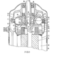
- Fig. 1 einen Radialkolbenverdichter, der zusammen mit dem als Außenläufer ausgebildeten Antriebsmotor in einem druckfesten Gehäuse angeordnet ist,
- Fig. 2 die von dem Zylinderblock überdeckte Fläche der feststehenden Achse in einer Abwicklung,
- Fig. 3 die abgewickelte Darstellung nach Fig. 2 im Schnitt entlang der Linie III-III,
- Fig. 4 eine andere Ausbildung der von dem Zylinderblock überdeckten Fläche der feststehenden Achse in einer Abwicklung,
- Fig. 5 die von dem Zylinderblock überdeckte Fläche der feststehenden Achse in perspektivischer Darstellung.
- 1 is a radial piston compressor, which is arranged together with the drive motor designed as an external rotor in a pressure-resistant housing,
- 2 the surface of the fixed axis covered by the cylinder block in a development,
- 3 shows the developed representation according to FIG. 2 in section along the line III-III,
- 4 shows another embodiment of the surface of the fixed axis covered by the cylinder block in a development,
- Fig. 5 shows the surface of the fixed axis covered by the cylinder block in a perspective view.
In Fig. 1 besteht der Radialkolbenverdichter aus einem auf einer feststehenden Achse 1 drehbar angeordneten Zylinderblock 2. An dem Zylinderblock 2 sind gleichmäßig über dessen Umfang verteilt mehrere zylindrische Kolbenräume 3 ausgebildet.. In jedem Kolbenraum 3 ist ein freibeweglicher Kolben 4 angeordnet. Die Kolben 4 bestehen aus einem topfförmigen Abstützteil 5, in das eine Kugel 6 eingelegt ist, die an einem Führungsring 7 abrollt. Der Führungsring 7 wird von einem Führungsteil 8 getragen, das gegenüber dem Zylinderblock 2 exzentrisch auf der feststehenden Achse 1 gelagert ist. Infolge dieser exzentrischen Anordnung des Zylinderblockes 2 gegenüber dem Führungsteil 8 werden die Kolben 4 in den Kolbenräumen 3 auf- und abbewegt. Bei der Darstellung nach Fig. 1 befindet sich der linke Kolben 4 in seiner unteren Totpunktstellung (UT) und der rechte Kolben 4 in seiner oberen Totpunktstellung (OT)1, the radial piston compressor consists of a cylinder block 2 rotatably arranged on a
Zum Antrieb des Radialkolbenverdichters ist als Antriebsmotor 11 ein Außenläufermotör vorgesehen, dessen Innenständer 9 auf der feststehenden Achse 1 befestigt ist. Der Außenläufer 10 ist über stirnseitig mit dem betreffenden Kurzschlußring 12 verbundene Arme 13 mit dem Zylinderblock 2 gekoppelt. Das aus dem Radialkolben-. verdichter und dem Antriebsmotor 11 .gebildete Verdichteraggregat ist in ein druckfestes Gehäuse 14 eingesetzt.To drive the radial piston compressor, an external rotor motor is provided as the
An dem verdichterseitigen Ende ist die feststehende Achse 1 hohl ausgebildet und dient als Zufuhrkanal 15 für das zu verdichtende Gas. In dem hohl ausgebildeten Teil der feststehenden Achse 1 ist konzentrisch eine Druckleitung 16 angebracht, die mit dem Druckschlitz 18 des Radialkolbenverdichters in Verbindung steht. Der Zufuhrkanal 15 hat Verbindung mit dem Saugschlitz 17 des Radialkolbenverdichters.At the compressor end, the
Die von dem Zylinderblock 2 auf der feststehenden Achse 1 überdeckte Fläche ist als Lagerfläche 19 ausgebildet. Auf dieser Lagerfläche 19 ist der Zylinderblock 2 mit- 'tels.eines Ringes 21 an dem die einzelnen Zylinder 20 angeordnet sind unmittelbar gelagert. Der Ring 21 bildet gleichzeitig den Boden der Kolbenräume 3. ' The surface covered by the cylinder block 2 on the fixed
Im Boden jedes Kolbenraumes 3 ist eine Öffnung 22 vorgesehen, die sich mit dem Saug- bzw. Druckschlitz 17 bzw. 18 überdeckt.In the bottom of each
In der feststehenden Achse 1 ist ferner ein sich bis zu deren unterem Ende erstreckender Bohrungskanal 24 ausgebildet. Mit diesem Bohrungskanal stehen zwei Querbohrungen 25 in Verbindung. Diese Querbohrungen 25 erstrecken sich bis zur Lagerfläche 19 und sind von dem Ring 21 überdeckt. Über den Bohrungskanal 24 wird mittels einer Pumpe Öl zugeführt, das durch die Querbohrungen 25 zwischen die Lagerfläche 19 und den Ring 21 des Zylinderblockes 2 gelangt.In the fixed
In Fig. 2 ist die von dem Zylinderblock 2 überdeckte Fläche 26 der feststehenden Achse 1 in einer Abwicklung dargestellt. Wie aus dieser Darstellung zu erkennen ist, erstreckt sich der Saugschlitz 17 nahezu bis zu dem unteren Totpunkt UT. Der Druckschlitz 18 ist wesentlich kürzer und endet am oberen Totpunkt OT. Auf der Strecke zwischen dem Saug- und dem Druckschlitz 17 und 18 erfolgt die Verdichtung des Gases. Zu beiden Seiten des Saugschlitzes 17 ist jeweils eine Nut 27 ausgebildet, die sich über den Druckschlitz 18 hinaus er- - streckt. In dem Bereich zwischen dem Saug- und dem Druckschlitz 17 und 18 ist die Nut 27 durch'zwei Breitenabstufungen 28 und wie die Schnittdarstellung nach Fig.3 zeigt, durch mehrere Tiefenabstufungen 29 in ihrem Querschnitt verringert, Das durch die Querbohrung 25 in die Nut 27 eingebrachte Öl wird von dem Zylinderblock 2 mitgeschleppt. Infolge der durch-die Abstufung 28 und 29 bedingten Querschnittsverminderung der Nut 27 wird das Öl einem immer höheren Druck ausgesetzt, der in etwa dem sich zwischem dem Saug- und dem Druckschlitz 17 und 18 aufbauenden Verdichtungsdruck entspricht bzw. sogar bei entsprechender Dimensionierung des Nutquerschnittes höher als der Verdichtungsdruck des Gases ist. Die Anbringung der beschriebenen Nuten 27 zu beiden Seiten des Saugschlitzes 17 und des Druckschlitzes 18 ist insbesondere bei einem Radialkolbenverdichter vorteilhaft, -bei dem der Zylinderblock 2 mittels eines Wälzlagers auf der feststehenden Achse 1 gelagert ist.2 shows the
In Fig. 4 ist die zur unmittelbaren Lagerung des Zylinderblockes 2 dienende Lagerfläche 19 in einer Abwicklung dargestellt. Zu beiden Seiten der Saugöffnung 17 ist jeweils eine Rinne 30 in der feststehenden Achse 1 ausgebildet. In die beiden Rinnen 30 münden wiederum die mit dem Bohrungskanal 24 verbundenen Querbohrungen 25. Die Rinnen 30 weisen z.B. eine Tiefenabstufung 31 auf und laufen an ihrem Ende, wie aus Fig. 5 zu erkennen ist, in einer Schräge 32 aus. Die durch die Tiefenabstufung 31 und/oder die Schräge 32 bedingte Querschnittsverminderung der Rinne 30 führt wiederum zu einem Druckanstieg des über die Querbohrung 25 in die Rinne 30 eingebrachten Öles. Die Rinnen 30 erstrecken sich nur etwa bis zum Ende des Saugschlitzes 17. Ein Anstieg des Ö1- druckes am Ende der Rinne 30 wird auch dann erreicht, wenn die Querschnittverringerung nicht innerhalb der Rinne 30 vorgenommen ist, sondern der Querschnitt des Spaltes zwischen dem Zylinderblock 2 und der feststehenden Achse 1 im Anschluß an die Rinne 30 kleiner ist als der Rinnenquerschnitt. Da der Zylinderblock 2 direkt auf der Lagerfläche 19 gelagert ist, erfolgt durch den in den Kolbenräumen herrschenden Verdichtungsdruck eine exzentrische Einstellung des Zylinderblockes gegenüber der Lagerfläche 19. Durch diese exzentrische Einstellung ergibt sich zwischen dem Ring 21 des Zylinderblockes 2 und der Lagerfläche 19 ein in seiner Weiten vom Saugschlitz 17 zum Druckschlitz 18 hin abnehmender Spalt. In den im Querschnitt verminderten Rinnen 30 wird der Öldruck bereits zum Ende des Saugschlitzes 17 hin etwas über den Ansaugdruck des Gases angehoben. Durch den sich zum Druckschlitz 18 hin weiter verengenden Spalt steigt der Öldruck ebenso wie der Verdichtungsdruck des Gases in den Kolbenräumen;3 stetig an.4 shows the bearing
In dem Umfangsbereich zwischen dem Saug- und Druckschlitz 17 und 18 ist in der Lagerfläche 19 ein Querschlitz 33 ausgebildet, der mindestens bis unter die Öffnung 22 im Boden der Kolbenräume 3 reicht. Über eine axiale Bohrung 34 ist eine Verbindung zwischen dem Querschlitz 33 und dem den Verdichter umgebenden Außenraum hergestellt. Ist der Drehkolbenverdichter zusammen mit seinem Antriebsmotor, wie in Fig. 1 dargestellt, in einem druckfesten Gehäuse 14 -eingebaut, so wird über den Querschlitz 33 und die axiale Bohrung 34 ein Druckausgleich mit dem druckfesten Gehäuse 14 hergestellt. Damit stellt sich im Innenraum des Gehäuses 14 ein Druck ein, der etwa dem Verdichtungsdruck entspricht, der an der Stelle des Querschlitzes 33 herrscht.In the peripheral area between the suction and
Bei dem beschriebenen Radialkolbenverdichter wird eine zufriedenstellende Abdichtung zwischen dem Zylinderblock 2 und der Lagerfläche 19 durch einen dem zwischen dem Saug- und dem Druckschlitz 17 und 18 ansteigenden Verdichtungsdruck entsprechenden Anstieg des Öldruckes in dem zwischen dem Zylinderblock 2 und der Lagerfläche 19 bestehenden Spalt erreicht. Je nach Art der Lagerung des Zylinderblockes 2 kann der Anstieg des Öldruckes durch verschiedene Maßnahmen bewirkt werden. Ist der Zylinderblock 2 mittels eines Wälzlagers auf der feststehenden Achse gelagert, so werden zu beiden Seiten des Saugschlitzes 17 Nuten 27 vorgesehen, deren Querschnitt zum Druckschlitz 18 hin vermindert, ist. Infolge dieser Querschnitttsverringerung ergibt sich ein Druckanstieg für das von dem Zylinderblock 2 mitgeschleppte Öl. Durch das Wälzlager und die Ausbilgung der Nuten 27 sind sowohl die Abmessungen des Spaltes zwischen dem Zylinderblock 2 und der von ihm überdeckten Fläche 26 der feststehenden Achse 1 als auch die Querschnittsverminderung der Nuten 27 festgelegt. Dementsprechend wird unabhängig von dem jeweiligen Verdichtungsdruck immer der gleiche Öldruck erzeugt. Durch entsprechende Gestaltung des Querschnittes der Nuten 27 kann dieser Öldruck so bemessen werden, daß er über dem höchsten Verdichtungsdruck liegt. Arbeitet der Verdichter mit niederen Verdirchtungsdrücken, dann besteht die Gefahr, daß das Öl in die Kolbenräume 3 vordringt.In the radial piston compressor described, a satisfactory seal between the cylinder block 2 and the bearing
Eine selbsttätige Anpassung des Öldruckes an den jeweiligen Verdichtungsdruck wird dadurch ermöglicht, daß der Zylinderblock 2 direkt auf der feststehenden Achse 1 gelagert ist. Die an der feststehenden Achse 1 ausgebildete Lagerflächq 19 bildet dann zusammen mit dem auf ihr aufliegenden Ring 21 des Zylinderblockes 2 ein Gleitlager. Der einseitig in dem Zylinderblock 2 wirkende Verdichtungsdruck führt zu einer exzentrischen Einstellung des Zylinderblockes 2 gegenüber der Lagerfläche 19 an der feststehenden Achse 1. Dort wo der Verdichtungsdruck am größten ist, wird der Zylinderblock 2 am stärksten an die Lagerfläche 19 angepreßt und damit stellt sich an dieser Stelle auch die kleinste Spaltweite ein. Als Folge dieser verkleinerten Spaltweite erhöht sich der Öldruck. Durch entsprechende Bemessung der Auflagefläche des Zylinderblockes 2 auf der Lagerfläche 19 kann in dem .Spalt ein dem Verdichtungsdruck entsprechender Öldruck erzeugt werden. Der auf der Lagerfläche 19 aufliegende Teil des Ringes 21 entspricht der wirksamen Breite der Spaltfläche.An automatic adjustment of the oil pressure to the respective compression pressure is made possible in that the cylinder block 2 is mounted directly on the fixed
In dem das Verdichteraggregat umschließenden druckfesten Gehäuse 14 stellt sich ein zwischen dem Ansaugdruck und dem'Verdichtungsdruck liegender Druck ein. Da in derartigen Radialkolbenverdichtern oft Gase verdichtet werden, die ein höheres spezifisches Gewicht als Luft haben, steigen mit dem erhöhten Druck in dem druckfesten Gehäuse 14 auch die Ventilationsverluste stark an. Zur Verminderung dieser Ventilationsverluste ist an dem Außenläufer 10 des Antriebsmotors 11 eine Glocke 35 befestigt, die den Zylinderblock 2 zumindest teilweise überdeckt.A pressure between the intake pressure and the compression pressure is established in the pressure-
Das im Innenraum der Glocke 35 befindliche Gas wird in Rotation versetzt und weist gegenüber dem ebenfalls rotierenden Zylinderblock 2 nur eine geringe Relativgeschwindigkeit auf, so daß sich auch nur geringe Ventilationsverluste ergeben. Andererseits entstehen an der glatten Außenseite der Glocke 35 gegenüber dem in dem druckfesten Gehäuse 14 befindlichen Gas ebenfalls nur geringe Ventilationsverluste. Durch entsprechende Anordnung des Querschlitzes 33 zwischen dem Saugschlitz 17 und dem Druckschlitz 18 kann der Druck in dem druckfesten Gehäuse 14 so eingestellt werden, daß die Spalt- und Ventilationsverluste ein Minimum erreichen.The gas located in the interior of the bell 35 is set in rotation and has only a low relative speed with respect to the likewise rotating cylinder block 2, so that there is also only a small ventilation ver lusts result. On the other hand, only slight ventilation losses occur on the smooth outside of the bell 35 compared to the gas located in the pressure-
Die Glocke 35 kann zusammen mit dem Kurzschlußring 12 und den Armen 13 in einem Arbeitsgang hergestellt werden. Wird die Wand der Glocke 35 zu dem offenen Ende der Glocke hin etwas nach außen geneigt, so kann durch eine solche Glocke eine Abscheidung von in dem Öl vorhandenen Verunreinigungen erreicht werden. Das aus dem Spalt zwischen dem Zylinderblock 2 und der Lagerfläche 19 austretende Öl tropft bzw. spritzt in die Glocke 35. Die durch die Rotation der Glocke 35 hervorgerufene Zentrifugalkraft läßt das Öl an der nach außen geneigten Wand der Glocke 35 zu deren offenem Ende hin abfließen. Die gegenüber dem Öl spezifisch schwereren Verunreinigungen bleiben dagegen an der Glockenwand haften. Durch ent- sprechende Gestaltung der Glockenwand, beispielsweise Anbringung eines Rauhbelages bzw. einer oder mehrerer umlaufenden Rillen kann die Reinigungswirkung noch verbessert werden.The bell 35 can be made together with the short-circuit ring 12 and the
Claims (15)
Priority Applications (1)
| Application Number | Priority Date | Filing Date | Title |
|---|---|---|---|
| AT82104321T ATE29769T1 (en) | 1981-05-25 | 1982-05-17 | RADIAL PISTON COMPRESSOR. |
Applications Claiming Priority (2)
| Application Number | Priority Date | Filing Date | Title |
|---|---|---|---|
| DE3120812 | 1981-05-25 | ||
| DE3120812A DE3120812C2 (en) | 1981-05-25 | 1981-05-25 | Radial piston compressor |
Publications (3)
| Publication Number | Publication Date |
|---|---|
| EP0069845A2 true EP0069845A2 (en) | 1983-01-19 |
| EP0069845A3 EP0069845A3 (en) | 1984-02-22 |
| EP0069845B1 EP0069845B1 (en) | 1987-09-16 |
Family
ID=6133195
Family Applications (1)
| Application Number | Title | Priority Date | Filing Date |
|---|---|---|---|
| EP82104321A Expired EP0069845B1 (en) | 1981-05-25 | 1982-05-17 | Radial piston compressor |
Country Status (7)
| Country | Link |
|---|---|
| US (1) | US4465436A (en) |
| EP (1) | EP0069845B1 (en) |
| JP (1) | JPS57200688A (en) |
| AT (1) | ATE29769T1 (en) |
| DE (2) | DE3120812C2 (en) |
| DK (1) | DK151146C (en) |
| IE (1) | IE53119B1 (en) |
Cited By (2)
| Publication number | Priority date | Publication date | Assignee | Title |
|---|---|---|---|---|
| DE3431158A1 (en) * | 1984-08-24 | 1986-03-06 | Alfred Teves Gmbh, 6000 Frankfurt | RADIAL PISTON MACHINE, IN PARTICULAR BALL PISTON PUMP |
| EP3489511A1 (en) * | 2017-11-28 | 2019-05-29 | Hoerbiger Automotive Komfortsysteme GmbH | Hydraulic system |
Families Citing this family (8)
| Publication number | Priority date | Publication date | Assignee | Title |
|---|---|---|---|---|
| DE3316106A1 (en) * | 1983-05-03 | 1984-11-08 | Siemens AG, 1000 Berlin und 8000 München | RADIAL PISTON COMPRESSORS |
| JPH0631633B2 (en) * | 1987-08-12 | 1994-04-27 | 株式会社ユニシアジェックス | Turbin type fuel pump |
| US5979440A (en) | 1997-06-16 | 1999-11-09 | Sequal Technologies, Inc. | Methods and apparatus to generate liquid ambulatory oxygen from an oxygen concentrator |
| US5988165A (en) * | 1997-10-01 | 1999-11-23 | Invacare Corporation | Apparatus and method for forming oxygen-enriched gas and compression thereof for high-pressure mobile storage utilization |
| US7204249B1 (en) * | 1997-10-01 | 2007-04-17 | Invcare Corporation | Oxygen conserving device utilizing a radial multi-stage compressor for high-pressure mobile storage |
| US8062003B2 (en) * | 2005-09-21 | 2011-11-22 | Invacare Corporation | System and method for providing oxygen |
| EP2467578A1 (en) * | 2009-08-17 | 2012-06-27 | Invacare Corporation | Compressor |
| EP2809949A4 (en) | 2012-02-03 | 2015-12-09 | Invacare Corp | Pumping device |
Citations (5)
| Publication number | Priority date | Publication date | Assignee | Title |
|---|---|---|---|---|
| DE720485C (en) * | 1936-10-07 | 1942-05-07 | Gustav Stromeier | Conveyor device for liquids |
| US3357361A (en) * | 1965-10-21 | 1967-12-12 | Bendix Corp | High velocity pump |
| DE2248312A1 (en) * | 1972-10-02 | 1974-04-11 | Bosch Gmbh Robert | RADIAL PISTON MACHINE |
| DE2710734A1 (en) * | 1977-03-11 | 1978-09-14 | Siemens Ag | COMPRESSORS WITH ECCENTRICALLY GUIDED, FREELY MOVING PISTONS |
| DE2832017A1 (en) * | 1978-07-20 | 1980-01-31 | Siemens Ag | Radial piston compressor drive - has cylinder block rotated by external rotor motor and piston cam track rotating on fixed eccentric shaft end |
Family Cites Families (7)
| Publication number | Priority date | Publication date | Assignee | Title |
|---|---|---|---|---|
| US1888860A (en) * | 1927-07-26 | 1932-11-22 | Arthur J Kercher | Compressor |
| US1846360A (en) * | 1928-01-27 | 1932-02-23 | Walter H Rudolph | Compressor |
| US1939057A (en) * | 1930-02-24 | 1933-12-12 | Arthur J Kercher | Compressor |
| US2515033A (en) * | 1948-05-25 | 1950-07-11 | Connor Arthur Albert | Reciprocating pump and compressor |
| US3037457A (en) * | 1959-08-26 | 1962-06-05 | Gen Electric | Pumps |
| DE2239757A1 (en) * | 1972-08-12 | 1974-02-21 | Bosch Gmbh Robert | RADIAL PISTON MACHINE |
| CH638590A5 (en) * | 1979-02-26 | 1983-09-30 | Sulzer Ag | HYDROSTATIC PISTON MACHINE. |
-
1981
- 1981-05-25 DE DE3120812A patent/DE3120812C2/en not_active Expired
-
1982
- 1982-05-17 DE DE8282104321T patent/DE3277321D1/en not_active Expired
- 1982-05-17 AT AT82104321T patent/ATE29769T1/en not_active IP Right Cessation
- 1982-05-17 EP EP82104321A patent/EP0069845B1/en not_active Expired
- 1982-05-18 US US06/379,553 patent/US4465436A/en not_active Expired - Fee Related
- 1982-05-24 IE IE1236/82A patent/IE53119B1/en unknown
- 1982-05-24 DK DK232082A patent/DK151146C/en not_active IP Right Cessation
- 1982-05-25 JP JP57088721A patent/JPS57200688A/en active Pending
Patent Citations (5)
| Publication number | Priority date | Publication date | Assignee | Title |
|---|---|---|---|---|
| DE720485C (en) * | 1936-10-07 | 1942-05-07 | Gustav Stromeier | Conveyor device for liquids |
| US3357361A (en) * | 1965-10-21 | 1967-12-12 | Bendix Corp | High velocity pump |
| DE2248312A1 (en) * | 1972-10-02 | 1974-04-11 | Bosch Gmbh Robert | RADIAL PISTON MACHINE |
| DE2710734A1 (en) * | 1977-03-11 | 1978-09-14 | Siemens Ag | COMPRESSORS WITH ECCENTRICALLY GUIDED, FREELY MOVING PISTONS |
| DE2832017A1 (en) * | 1978-07-20 | 1980-01-31 | Siemens Ag | Radial piston compressor drive - has cylinder block rotated by external rotor motor and piston cam track rotating on fixed eccentric shaft end |
Cited By (2)
| Publication number | Priority date | Publication date | Assignee | Title |
|---|---|---|---|---|
| DE3431158A1 (en) * | 1984-08-24 | 1986-03-06 | Alfred Teves Gmbh, 6000 Frankfurt | RADIAL PISTON MACHINE, IN PARTICULAR BALL PISTON PUMP |
| EP3489511A1 (en) * | 2017-11-28 | 2019-05-29 | Hoerbiger Automotive Komfortsysteme GmbH | Hydraulic system |
Also Published As
| Publication number | Publication date |
|---|---|
| DK232082A (en) | 1982-11-26 |
| DE3277321D1 (en) | 1987-10-22 |
| JPS57200688A (en) | 1982-12-08 |
| DE3120812A1 (en) | 1982-12-23 |
| ATE29769T1 (en) | 1987-10-15 |
| DE3120812C2 (en) | 1984-04-19 |
| DK151146B (en) | 1987-11-09 |
| DK151146C (en) | 1988-07-18 |
| US4465436A (en) | 1984-08-14 |
| IE53119B1 (en) | 1988-07-06 |
| EP0069845A3 (en) | 1984-02-22 |
| IE821236L (en) | 1982-11-25 |
| EP0069845B1 (en) | 1987-09-16 |
Similar Documents
| Publication | Publication Date | Title |
|---|---|---|
| DE3237803A1 (en) | ROTATIONAL COMPRESSOR | |
| DE3248407A1 (en) | SCREW COMPRESSORS | |
| EP0069845B1 (en) | Radial piston compressor | |
| DE4441915C2 (en) | Internal gear pump | |
| DE3343908A1 (en) | MACHINE, ESPECIALLY WORKING MACHINE FOR COMPRESSING AND CONVEYING FLUIDS OF ALL TYPES | |
| DE4002221C2 (en) | Swash plate compressor with thrust bearing lubrication | |
| DE2710734C3 (en) | ||
| DE2328365C2 (en) | Rotary vacuum pump | |
| DE19920168A1 (en) | Radial piston pump of camshaft and cylinders for vehicle media | |
| DE2203278A1 (en) | AXIAL PISTON MACHINE | |
| DE2351856C3 (en) | ||
| DE8115575U1 (en) | RADIAL PISTON COMPRESSORS | |
| DE676147C (en) | Pump for pumping liquid fuels | |
| DE3152386C2 (en) | Radial piston compressor | |
| DE1812635A1 (en) | Radial piston pump | |
| DE2805492A1 (en) | Cooling system for axial piston unit - has annular groove in cylinder wall portion at all times covered by moving piston | |
| DE3245974C2 (en) | ||
| DE2263837A1 (en) | RADIAL PISTON PUMP | |
| DE19704752A1 (en) | Needle bearing esp. for radial piston pump | |
| DE2311048C3 (en) | Compressor piston | |
| DE3729319C2 (en) | Scroll compressor | |
| DE3246782C2 (en) | ||
| DE2254751B2 (en) | Radial piston machine | |
| CH322416A (en) | Rotary piston machine | |
| DE2821389A1 (en) | Piston compressor with coaxial pistons connected in tandem - uses common rod and crank mechanism acting on rod to reciprocate pistons (NL 21.11.78) |
Legal Events
| Date | Code | Title | Description |
|---|---|---|---|
| PUAI | Public reference made under article 153(3) epc to a published international application that has entered the european phase |
Free format text: ORIGINAL CODE: 0009012 |
|
| AK | Designated contracting states |
Designated state(s): AT BE CH DE FR GB IT LI NL SE |
|
| PUAL | Search report despatched |
Free format text: ORIGINAL CODE: 0009013 |
|
| AK | Designated contracting states |
Designated state(s): AT BE CH DE FR GB IT LI NL SE |
|
| 17P | Request for examination filed |
Effective date: 19840329 |
|
| GRAA | (expected) grant |
Free format text: ORIGINAL CODE: 0009210 |
|
| AK | Designated contracting states |
Kind code of ref document: B1 Designated state(s): AT BE CH DE FR GB IT LI NL SE |
|
| REF | Corresponds to: |
Ref document number: 29769 Country of ref document: AT Date of ref document: 19871015 Kind code of ref document: T |
|
| PG25 | Lapsed in a contracting state [announced via postgrant information from national office to epo] |
Ref country code: SE Effective date: 19870930 |
|
| REF | Corresponds to: |
Ref document number: 3277321 Country of ref document: DE Date of ref document: 19871022 |
|
| ET | Fr: translation filed | ||
| ITF | It: translation for a ep patent filed | ||
| GBT | Gb: translation of ep patent filed (gb section 77(6)(a)/1977) | ||
| PLBE | No opposition filed within time limit |
Free format text: ORIGINAL CODE: 0009261 |
|
| STAA | Information on the status of an ep patent application or granted ep patent |
Free format text: STATUS: NO OPPOSITION FILED WITHIN TIME LIMIT |
|
| 26N | No opposition filed | ||
| PGFP | Annual fee paid to national office [announced via postgrant information from national office to epo] |
Ref country code: GB Payment date: 19890430 Year of fee payment: 8 |
|
| PGFP | Annual fee paid to national office [announced via postgrant information from national office to epo] |
Ref country code: AT Payment date: 19890503 Year of fee payment: 8 |
|
| PG25 | Lapsed in a contracting state [announced via postgrant information from national office to epo] |
Ref country code: LI Effective date: 19890531 Ref country code: CH Effective date: 19890531 Ref country code: BE Effective date: 19890531 |
|
| PG25 | Lapsed in a contracting state [announced via postgrant information from national office to epo] |
Ref country code: NL Effective date: 19891201 |
|
| NLV4 | Nl: lapsed or anulled due to non-payment of the annual fee | ||
| PG25 | Lapsed in a contracting state [announced via postgrant information from national office to epo] |
Ref country code: FR Free format text: LAPSE BECAUSE OF NON-PAYMENT OF DUE FEES Effective date: 19900131 |
|
| REG | Reference to a national code |
Ref country code: CH Ref legal event code: PL |
|
| PG25 | Lapsed in a contracting state [announced via postgrant information from national office to epo] |
Ref country code: DE Effective date: 19900201 |
|
| REG | Reference to a national code |
Ref country code: FR Ref legal event code: ST |
|
| PG25 | Lapsed in a contracting state [announced via postgrant information from national office to epo] |
Ref country code: GB Effective date: 19900517 Ref country code: AT Effective date: 19900517 |
|
| GBPC | Gb: european patent ceased through non-payment of renewal fee |