EP0069402B1 - Apparatus for buffing and non-destructive testing of tyres - Google Patents
Apparatus for buffing and non-destructive testing of tyres Download PDFInfo
- Publication number
- EP0069402B1 EP0069402B1 EP82106346A EP82106346A EP0069402B1 EP 0069402 B1 EP0069402 B1 EP 0069402B1 EP 82106346 A EP82106346 A EP 82106346A EP 82106346 A EP82106346 A EP 82106346A EP 0069402 B1 EP0069402 B1 EP 0069402B1
- Authority
- EP
- European Patent Office
- Prior art keywords
- tyre
- rings
- transmitter
- buffing
- testing
- Prior art date
- Legal status (The legal status is an assumption and is not a legal conclusion. Google has not performed a legal analysis and makes no representation as to the accuracy of the status listed.)
- Expired
Links
Images


Classifications
-
- G—PHYSICS
- G01—MEASURING; TESTING
- G01N—INVESTIGATING OR ANALYSING MATERIALS BY DETERMINING THEIR CHEMICAL OR PHYSICAL PROPERTIES
- G01N29/00—Investigating or analysing materials by the use of ultrasonic, sonic or infrasonic waves; Visualisation of the interior of objects by transmitting ultrasonic or sonic waves through the object
- G01N29/44—Processing the detected response signal, e.g. electronic circuits specially adapted therefor
- G01N29/449—Statistical methods not provided for in G01N29/4409, e.g. averaging, smoothing and interpolation
-
- G—PHYSICS
- G01—MEASURING; TESTING
- G01M—TESTING STATIC OR DYNAMIC BALANCE OF MACHINES OR STRUCTURES; TESTING OF STRUCTURES OR APPARATUS, NOT OTHERWISE PROVIDED FOR
- G01M17/00—Testing of vehicles
- G01M17/007—Wheeled or endless-tracked vehicles
- G01M17/02—Tyres
- G01M17/025—Tyres using infrasonic, sonic or ultrasonic vibrations
-
- G—PHYSICS
- G01—MEASURING; TESTING
- G01N—INVESTIGATING OR ANALYSING MATERIALS BY DETERMINING THEIR CHEMICAL OR PHYSICAL PROPERTIES
- G01N29/00—Investigating or analysing materials by the use of ultrasonic, sonic or infrasonic waves; Visualisation of the interior of objects by transmitting ultrasonic or sonic waves through the object
- G01N29/22—Details, e.g. general constructional or apparatus details
- G01N29/26—Arrangements for orientation or scanning by relative movement of the head and the sensor
- G01N29/27—Arrangements for orientation or scanning by relative movement of the head and the sensor by moving the material relative to a stationary sensor
-
- G—PHYSICS
- G01—MEASURING; TESTING
- G01N—INVESTIGATING OR ANALYSING MATERIALS BY DETERMINING THEIR CHEMICAL OR PHYSICAL PROPERTIES
- G01N29/00—Investigating or analysing materials by the use of ultrasonic, sonic or infrasonic waves; Visualisation of the interior of objects by transmitting ultrasonic or sonic waves through the object
- G01N29/34—Generating the ultrasonic, sonic or infrasonic waves, e.g. electronic circuits specially adapted therefor
- G01N29/341—Generating the ultrasonic, sonic or infrasonic waves, e.g. electronic circuits specially adapted therefor with time characteristics
- G01N29/343—Generating the ultrasonic, sonic or infrasonic waves, e.g. electronic circuits specially adapted therefor with time characteristics pulse waves, e.g. particular sequence of pulses, bursts
Definitions
- This invention is generally directed to methods and apparatus for the buffing and non-destructive testing of rubber tyres.
- Prior tyre chucking mechanisms in general have included axially movable tyre mounting rims for quickly mounting and inflating a test tyre.
- Prior NDI machines have located an ultrasonic transmitter inside a rotatable inflated tyre, albeit such have been only fixed or manually adjustable mounting arrangements.
- Other NDI machines have included articulated transmitter mounting arrangement in conjunction with a spread-open non-inflated test tyre.
- apparatus for buffing and for non-destructively testing a buffed tyre carcass said apparatus being characterised by opposed circular rings for sealingly engaging the corresponding rims of said tyre, tyre inflation means which inflate said tyre after engagement by said rings, buffing means for rotating said inflated tyre and for buffing away the outer tread wall surfaces to provide a substantially uniform outside tread wall surface on the resulting tyre carcass, ultrasonic testing means disposed both inside and outside the inflated tyre for measuring the relative strengths of ultrasonic acoustic signals transmitted through different areas of said buffed tread wall as it is rotated thereby non-destructively testing the buffed tyre carcass.
- a method for buffing and for non-destructively testing a buffed tyre carcass said method being characterised by using one unified apparatus for sealingly engaging the rims of said tyre between opposing rings, inflating said tyre after engagement by said rings, rotating said inflated tyre and buffing away the outer tread wall surfaces to provide a substantially uniform outside tread wall surface on the resulting tyre carcass, and measuring the relative strengths of ultrasonic acoustic signals transmitted through different areas of said buffed tread wall while it is still inflated and as it is rotated thereby non-destructively testing the buffed tyre carcass.
- plural transmitting acoustic transducers are located inside a revolving inflated tyre so as to acoustically illuminate the entire inside tyre surfaces under test.
- the preferred embodiment includes multiplexing circuitry to insure that only a single transducer is activated at a given time. Apparatus incorporating multiplexing means is described and claimed in EP Patent Specification No. 59961.
- Plural acoustic receiving transducers are arrayed about the outer tyre walls so as to receive acoustic signals transmitted therethrough from the transmitting transducers located inside the tyre.
- Each receiving transducer is preferably collimated and matched to the ambient air impedance with a cylindrical tube having an inner conical surface which tapers down to the sensing area of the actual receiving transducer. Such collimation helps to confine each receiver's output to represent acoustic signals transmitted through a limited area of the tyre wall and further helps to reject interference from tread patterns and ambient noise.
- Flaws in the tyres such as separations between cord layers and rubber layers or between various rubber layers attenuate the acoustic signals passing therethrough to a greater extent than when the acoustic signals pass through a normal section of the tyre wall.
- an inflated tyre in the preferred embodiment has been discovered to assist in maintaining a true running tyre surface and thus avoids signal variations that might otherwise be caused by wobbling or other relative axial motions of the tyre walls during rotation.
- the inflated tyre is also useful in helping to at least partially stress the tyre walls, as they will be stressed during normal use, and to open up leakage passageways through the tyre walls so that they may be detected by ultrasonic detection of air passing therethrough. Approximately only 0.345 bar is needed to maintain a stable inflated tyre structure. However, it has been discovered that improved signal transmission and overall performance occurs if the tyre is inflated within the range of approximately 1.034-1.241 bar.
- the preferred exemplary embodiment of this invention also includes special mechanical features for automatically moving the acoustic transducers into and out of operative position with respect to the inflated tyre walls.
- the acoustic transmitters are retracted inwardly both radially and axially with respect to at least one tyre mounting ring or flange so as both to facilitate the tyre mounting and demounting operations and to protect the acoustic transmitters from possible physical damage.
- these acoustic transmitters are moved radially outwardly inside the inflated tyre into an operative position with respect to the inside tyre walls.
- the relative axial movement of the acoustic transmitters with respect to a tyre mounting flange or ring is achieved by spring loading the tyre ring so that it axially moves away from the acoustic transmitters thereby uncovering them during the tyre mounting operation and thus providing proper clearance for subsequent radially outward movement into the inflated tyre carcass.
- spring loading also helps in properly seating the tyre rims with the mounting flanges or rings during mounting and inflation operations.
- the ultrasonic bursts and receiver gating periods are preferably synchronized to occur at corresponding successive incremental positions of the rotating tyre such that the final display or defect indication may be accurately located with respect to an index mark on the tyre and/or tyre mounting flange or the like.
- EP Patent Specification Nos. 61045 and 18747 which also describe and claim tyre inspection apparatus.
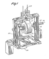
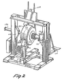
- the major mechanical components of the machine are mounted to an open frame 100 having a fixed spindle 102 and an axially movable spindle 104 opposingly aligned along horizontal axis 106.
- Conventional circular tyre mounting rings or flanges 108 and 110 are attached to the outer rotatable ends of spindles 102 and 104 for mounting an inflated tyre 112, therebetween.
- a conventional pneumatically operated tyre lift mechanism 114 is conveniently provided so as to assist the human operator in lifting and swinging a tyre into and out of place between rings 108 and 110 during tyre mounting and demounting operations.
- Ring 108 is driven by a two horsepower d.c. motor 116 through reducing gears 118.
- a tyre surface speed of approximately 189.2 metres per minute is preferred for buffing operations while a much lower speed of approximately 12.2 metres per minute is preferred for NDI operations.
- Spindle 104, and hence ring 110 is axially extended and retracted by pneumatic cylinder 120.
- ring 110 is retracted by cylinder 120 so as to permit the tyre 112 to be lifted into place on ring 108 by lift 114. Thereafter, ring 110 is extended against the corresponding rim of tyre 112 and the tyre is inflated to a desired set point pressure by compressed air passed through the centre of spindle 102.
- a conventional rotating tyre buffing rasp 200 is mounted on a vertical pedestal 202 situated on the backside of the machine as seen in Figure 2.
- the rasp 200 is controlled via a conventional panel 204 to move laterally along a desired buffing path and horizontally towards and away from the tyre by conventional control mechanisms including a "joy stick" used to control a pneumatic cylinder, lead screws and associated drive motors and the like.
- the buffer rasp 200 is rotated by a separate motor mounted on pedestal 202.
- the buffer mechanism, per se, is of a conventional type as marketed by Bandag, Inc., e.g. Buffer Model No. 23A.
- An array of 16 ultrasonic acoustic receiving transducers 210 is disposed above and around the outer walls of tyre 112.
- the receivers 210 preferably include a conically shaped collimator and/or focusing tube to help limit the field of view for each individual transducer to a relatively small and unique area across the tyre wall.
- the receivers 210 may be conveniently potted either individually or in groups in polyurethane foam or the like to help mechanically fix the receivers in their respective desired positions, to help protect the receivers and to help isolate the receivers from spurious ambient acoustic signals.
- the array of receivers 210 is radially adjusted into operative position by an air cylinder 212 having a coupled hydraulic control cylinder so as to define a radially extended operative position for the receivers 210.
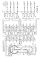
- FIG. 3 A block diagram of the combined tyre buffer/ NDI machine and its associated electrical and pneumatic circuits is shown in Figure 3.
- the electrical motor and pneumatic cylinder controls 300 are of entirely conventional design and thus not shown in detail. Operator inputs depicted at the left of Figure 3 are made directly or indirectly by the operator via conventional electrical switches, relays, air valves and/or liquid control valves.
- a tyre is placed on lift 114 and raised into position between the rings 108 and 110.
- a predetermined index position on the tyre is aligned with a physical index position on flange 108.
- the chucking apparatus is engaged by causing flange 110 to move into the tyre 112 so as to pinch the tyre beads together in preparation for tyre inflation.
- the tyre is then inflated to a desired set point pressure.
- the flange 108 is spring-loaded such that during chuck engagement and tyre inflation, it is caused to move axially outwardly against the spring-loading (e.g. by approximately 5.1 centimetres).
- An interlock switch activated by air pressure and/or by the physical movement of flange 108 may be used to prevent any premature extension of the transmitter before it is uncovered from its protected position.
- the buffing rasp drive motors are conventionally activated and controlled (e.g. with a "joy stick" and conventional push button controls) to buff the tyre tread surface as desired.
- a "joy stick” and conventional push button controls e.g. with a "joy stick" and conventional push button controls
- Such buffing is believed to avoid possible spurious indications of defects caused by normal tread patterns and/or by uneven wear about the tyre surface.
- an ultrasonic transmitter located inside the inflated tyre 112 is extended into operative position and the array of receivers 210 is lowered into operative position by respectively associated pneumatic cylinders.
- the same 2-horsepower d.c. motor which drives the tyre at approximately 182.9 surface metres per minute during buffing operations may be reduced in speed by conventional electrical circuits so as to drive the tyre at approximately 12.2 surface metres per minute during the NDI mode.
- the operator may activate the scan request input switch to the ultrasonic NDI circuits 302.
- tyre 112 will be ultrasonically inspected during one or more complete tyre revolutions to produce a display 304 which can be humanly interpreted directly or indirectly to reveal the condition of the tyre (e.g. satisfactory for further buffing and retreading, doubtful or unsatisfactory). If questionable condition is indicated, the tyre may be discarded or may be additionally buffed and retested.
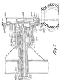
- ultrasonic acoustic transmitting crystals 500 and 502 are disposed inside inflated tyre 112, which is chucked between rings 108 and 110, rotatably secured to spindles 102 and 104, respectively.
- the electrical leads feeding transmitters 500 and 502 are fed out through the fixed spindle 102 to the transmitter activation circuits.
- Inflation air is likewise fed in through the centre of spindle 102 as are pneumatic lines and/or other control connections for extending and retracting the transmitters.
- the exemplary ultrasonic transmitters 500 and 502 have a radiation field which substantially illuminates a sector of approximately 90°. Hence, they are mounted at 90° with respect to one another on block 504 which may, for example, be formed from polyvinyl chloride plastic materials. It has been found that acceptable operation will not result if the transmitters are too close to the inside tyre surfaces or too far away from these surfaces. In the preferred exemplary embodiment, transmitting crystals 500 and 502 are approximately 5.1 centimetres from the inner tyre wall surfaces although this optimum distance of separation may be varied by a considerable amount (e.g. plus or minus approximately 2.5 centimetres).
- the arrayed receiving transducers 210 are located about an arc generally corresponding to the outside shape of the tyre wall. Here again, it has been found that acceptable operation does not result if the receivers are too close or too far away from the outer tyre walls. Preferably, the receivers are no closer than approximately 2.5 centimetres to the outer tyre surface but are preferably within 14.0 to 21.6 centimetres of the opposingly situated transmitting crystal.
- the receiving transducers 210 preferably each employ a conically shaped collimator and/or focusing tube as shown in detail at Figure 5. These tubes are preferably machined from polyvinyl chloride plastic material and also help to match the impedance of the actual transducer crystal surface to the surrounding ambient air acoustic impedance.
- a moderately high ultrasonic frequency is employed so as to help avoid interference from spurious ambient acoustic signals and to obtain increased resolution by using shorter wavelength acoustic signals while at the same time avoiding ultra-high frequency acoustic signals and the problems associated therewith.
- Frequencies above 40 kHz are desirable with 75 kHz being chosen as the presently preferred optimum frequency.
- Ultrasonic transducing crystals operating at 75 kHz are conventionally available.
- receiving crystals are available as the MK-111 transducer from Massa Corporation, Windom, Massachusetts, having the following specifications:
- a suitable transmitting crystal tuned to approximately 75 kHz is available from Ametek/Straza, California under No. 8-6A016853.
- the electrical leads from each of the transducers 210 are preferably connected through coaxial cables 506 to their respectively associated pre-amplifiers 508.
- the outputs from each of the 16 amplifiers 508 are connected to an eight pole double throw electronic switch comprising Signetics SD5000 integrated circuits, controlled by the HIGH CHAN multiplexing signal provided by system interface 416.
- the eight resulting multiplexed output channels are connected through transistor buffer amplifiers to signal processing channels A-H. Accordingly, in the absence of a HIGH CHAN multiplex signal, the outputs from the first eight pre-amplifiers 508 are coupled to respectively corresponding signal processing channels A-H. However, when the HIGH CHAN multiplexing signal is present, the outputs from the last eight of the pre-amplifiers 508 are connected to respectively corresponding signal processing channels A-H.
- the transmitting crystals 500 and 502 are directed at 90° with respect to one another from the face of a PVC mounting block 1500.
- the block 1500 is, in turn, attached to a retractable rod 1502 connected to the piston of a pneumatic cylinder 1504.
- the pneumatic cylinder 1504 has retracted the transmitting crystals 500 and 502 into a protected area defined by an annular plate 1506 attached to the tyre mounting ring or flange 108.
- the tyre mounting ring 108 is rotatably secured to the fixed spindle 102 through ball-bearing assemblies 1508 and 1510. This rotatable connection is maintained airtight by rotating seal assembly 1512.
- the centre of the spindle 102 is hollow so as to permit passage of pneumatic control line 1514 and of the transmitter electrical leads therethrough.
- the rotating ring 108 and its connected assembly is spring-loaded via spring 1519 to its axially extended position as shown in Figure 6.
- the ring 108 may be moved axially to the position shown in dotted lines against the spring force.
- such motion begins to occur when the ring 108 has approximately 679 kg (0.138 bar) of lateral force applied thereto.
- the sliding joint which permits such motion is also maintained airtight by "O" ring 1516.
- no more than approximately two inches of axial movement are permitted before the spring force is sufficient to resist further movement even when the tyre is inflated to approximately 1.034-1.241 bar.
Landscapes
- Physics & Mathematics (AREA)
- General Physics & Mathematics (AREA)
- General Health & Medical Sciences (AREA)
- Chemical & Material Sciences (AREA)
- Analytical Chemistry (AREA)
- Biochemistry (AREA)
- Life Sciences & Earth Sciences (AREA)
- Health & Medical Sciences (AREA)
- Immunology (AREA)
- Pathology (AREA)
- Probability & Statistics with Applications (AREA)
- Engineering & Computer Science (AREA)
- Signal Processing (AREA)
- Investigating Or Analyzing Materials By The Use Of Ultrasonic Waves (AREA)
Applications Claiming Priority (6)
| Application Number | Priority Date | Filing Date | Title |
|---|---|---|---|
| US06/031,962 US4266428A (en) | 1979-04-19 | 1979-04-19 | Method and apparatus for non-destructive inspection of tires |
| US31962 | 1979-04-19 | ||
| US06/031,963 US4275589A (en) | 1979-04-19 | 1979-04-19 | Method and apparatus for non-destructive inspection of tires |
| US31961 | 1979-04-19 | ||
| US31963 | 1979-04-19 | ||
| US06/031,961 US4285235A (en) | 1979-04-19 | 1979-04-19 | Method and apparatus for non-destructive inspection of tires |
Related Parent Applications (1)
| Application Number | Title | Priority Date | Filing Date |
|---|---|---|---|
| EP80301203.8 Division | 1980-04-16 |
Publications (2)
| Publication Number | Publication Date |
|---|---|
| EP0069402A1 EP0069402A1 (en) | 1983-01-12 |
| EP0069402B1 true EP0069402B1 (en) | 1985-08-07 |
Family
ID=27363995
Family Applications (6)
| Application Number | Title | Priority Date | Filing Date |
|---|---|---|---|
| EP82106346A Expired EP0069402B1 (en) | 1979-04-19 | 1980-04-16 | Apparatus for buffing and non-destructive testing of tyres |
| EP80301203A Expired EP0018747B1 (en) | 1979-04-19 | 1980-04-16 | Method and apparatus for non-destructive testing of tires |
| EP82101766A Expired EP0059961B1 (en) | 1979-04-19 | 1980-04-16 | Method and apparatus for non-destructive inspection of tyres |
| EP82101765A Expired EP0061045B1 (en) | 1979-04-19 | 1980-04-16 | Method and apparatus for non-destructive inspection of tyres |
| EP82101767A Expired EP0060469B1 (en) | 1979-04-19 | 1980-04-16 | Method and apparatus for non-destructive inspection of tyres |
| EP82101768A Expired EP0060470B1 (en) | 1979-04-19 | 1980-04-16 | Method and apparatus for non-destructive inspection of tyres |
Family Applications After (5)
| Application Number | Title | Priority Date | Filing Date |
|---|---|---|---|
| EP80301203A Expired EP0018747B1 (en) | 1979-04-19 | 1980-04-16 | Method and apparatus for non-destructive testing of tires |
| EP82101766A Expired EP0059961B1 (en) | 1979-04-19 | 1980-04-16 | Method and apparatus for non-destructive inspection of tyres |
| EP82101765A Expired EP0061045B1 (en) | 1979-04-19 | 1980-04-16 | Method and apparatus for non-destructive inspection of tyres |
| EP82101767A Expired EP0060469B1 (en) | 1979-04-19 | 1980-04-16 | Method and apparatus for non-destructive inspection of tyres |
| EP82101768A Expired EP0060470B1 (en) | 1979-04-19 | 1980-04-16 | Method and apparatus for non-destructive inspection of tyres |
Country Status (10)
| Country | Link |
|---|---|
| EP (6) | EP0069402B1 (enExample) |
| AR (1) | AR232045A1 (enExample) |
| AU (3) | AU533025B2 (enExample) |
| BR (1) | BR8002432A (enExample) |
| DE (1) | DE3065656D1 (enExample) |
| DK (6) | DK163945C (enExample) |
| FI (1) | FI72817C (enExample) |
| IN (1) | IN156268B (enExample) |
| MX (2) | MX150114A (enExample) |
| NZ (1) | NZ193066A (enExample) |
Families Citing this family (14)
| Publication number | Priority date | Publication date | Assignee | Title |
|---|---|---|---|---|
| GB2204403B (en) * | 1987-05-05 | 1991-07-17 | David John Howard Peacock | "method of detecting leaks" |
| JP2602863B2 (ja) * | 1987-12-25 | 1997-04-23 | 株式会社ブリヂストン | 空気入りタイヤの非破壊検査方法 |
| CA2014435C (en) * | 1989-04-12 | 1999-06-22 | Mirek Macecek | Ultrasonic tire testing method and apparatus |
| WO1990013814A1 (en) * | 1989-05-01 | 1990-11-15 | Hamersley Iron Pty. Limited | Ultrasonic wheel testing |
| ATE221991T1 (de) * | 1997-06-10 | 2002-08-15 | Beissbarth Gmbh | Reifenprüfverfahren und -vorrichtung |
| EP0884560B1 (de) * | 1997-06-10 | 2005-10-26 | Beissbarth GmbH | Verfahren und Vorrichtung zum Prüfen von Reifen |
| DE102013102296B4 (de) | 2012-12-21 | 2018-11-08 | Bernward Mähner | Vorrichtung und Verfahren zum Prüfen eines Reifens mittels eines interferometrischen Messverfahrens |
| CN105675312B (zh) * | 2016-01-25 | 2019-01-01 | 中国汽车技术研究中心 | 一种模拟整车状态下车轮力传递函数测试方法及装置 |
| CN105510057B (zh) * | 2016-01-25 | 2019-01-01 | 中国汽车技术研究中心 | 一种自由状态下车轮力传递函数测试方法及装置 |
| CN109506847A (zh) * | 2017-09-15 | 2019-03-22 | 国网安徽省电力公司濉溪县供电公司 | 变压器箱体超声波自动检漏装置 |
| DE102019218422A1 (de) * | 2019-11-28 | 2021-06-02 | Continental Reifen Deutschland Gmbh | Fahrzeug umfassend mindestens ein Fahrzeugrad mit einem einen Reifeninnenraum umfassenden Fahrzeugluftreifen und ein, zwei oder mindestens drei Schallwellenempfänger zum mehrfachen oder kontinuierlichen Erfassen von Luftschallwellensignalen, Vorrichtung zur Verwendung in dem besagten Fahrzeug und eine Verwendung der Vorrichtung sowie ein entsprechendes Verfahren. |
| CN113446908B (zh) * | 2021-07-20 | 2022-11-15 | 山西新华防化装备研究院有限公司 | 气囊爆破试验夹具 |
| CN117949516A (zh) * | 2024-03-22 | 2024-04-30 | 山西天和盛环境检测股份有限公司 | 一种水体检测装置 |
| CN118493339B (zh) * | 2024-07-16 | 2024-10-25 | 东海县通灵电器有限公司 | 一种继电器检测设备 |
Family Cites Families (17)
| Publication number | Priority date | Publication date | Assignee | Title |
|---|---|---|---|---|
| US2378237A (en) * | 1942-09-02 | 1945-06-12 | Wingfoot Corp | Method and apparatus for ultrasonic testing |
| US2695520A (en) * | 1951-09-19 | 1954-11-30 | Us Rubber Co | Tire testing machine |
| US3336794A (en) * | 1964-07-30 | 1967-08-22 | Alfred J Wysoczanski | Ultrasonic tire tester |
| NL6609733A (enExample) * | 1966-07-12 | 1968-01-15 | ||
| US3500676A (en) * | 1968-03-15 | 1970-03-17 | Gulf Research Development Co | Methods and apparatus for detecting leaks |
| US3550443A (en) * | 1968-11-19 | 1970-12-29 | Morris A Sherkin | Method and apparatus for inspecting tires |
| DE2016333A1 (de) * | 1969-04-09 | 1970-11-12 | Deutsche Semperit Gummiwerk GmbH, 8OOO München | Verfahren zur Prüfung eines Hohlkörpers, insbesondere eines Handschuhes, auf Lochfreiheit und Vorrichtungen zur Durchführung dieses Verfahrens |
| US3698233A (en) * | 1970-02-02 | 1972-10-17 | Goodyear Tire & Rubber | Apparatus for processing cured tires |
| US3948094A (en) * | 1971-10-01 | 1976-04-06 | Gebr. Hofmann | Receiving fixture for tires of motor vehicle wheels |
| GB1385738A (en) * | 1971-10-06 | 1975-02-26 | Picker Corp | Inspection of tyres |
| US3882717A (en) * | 1973-06-20 | 1975-05-13 | James Electronics Inc | Self-adjusting ultrasonic tire inspection device |
| US3877506A (en) * | 1974-04-08 | 1975-04-15 | John R Mattox | Tire buffing machine |
| CA1093674A (en) * | 1975-10-13 | 1981-01-13 | George Kossoff | Ultrasonic beam scanning |
| DE2632674B2 (de) * | 1976-07-16 | 1978-06-08 | Karl Deutsch Pruef- Und Messgeraetebau, 5600 Wuppertal | Elektronische Einrichtung zur taktweisen Erfassung, Aus- und Bewertung von Impulsen bei der zerstörungsfreien Ultraschall-Werkstoffprüfung |
| US4059989A (en) * | 1976-12-10 | 1977-11-29 | The Goodyear Tire & Rubber Company | Non-destructive examination of an article particularly a tire, with ultrasonic energy |
| US4160386A (en) * | 1977-06-09 | 1979-07-10 | Southwest Research Institute | Ultrasonic inspection system including apparatus and method for tracking and recording the location of an inspection probe |
| GB1604149A (en) * | 1978-05-31 | 1981-12-02 | Btr Industries Ltd | Ultrasonic detection of faults in conveyor belts |
-
1980
- 1980-03-07 IN IN165/DEL/80A patent/IN156268B/en unknown
- 1980-03-07 NZ NZ193066A patent/NZ193066A/en unknown
- 1980-03-18 AR AR280350A patent/AR232045A1/es active
- 1980-04-02 DK DK146680A patent/DK163945C/da not_active IP Right Cessation
- 1980-04-14 AU AU57431/80A patent/AU533025B2/en not_active Expired
- 1980-04-14 FI FI801189A patent/FI72817C/fi not_active IP Right Cessation
- 1980-04-16 DE DE8080301203T patent/DE3065656D1/de not_active Expired
- 1980-04-16 EP EP82106346A patent/EP0069402B1/en not_active Expired
- 1980-04-16 EP EP80301203A patent/EP0018747B1/en not_active Expired
- 1980-04-16 EP EP82101766A patent/EP0059961B1/en not_active Expired
- 1980-04-16 EP EP82101765A patent/EP0061045B1/en not_active Expired
- 1980-04-16 EP EP82101767A patent/EP0060469B1/en not_active Expired
- 1980-04-16 EP EP82101768A patent/EP0060470B1/en not_active Expired
- 1980-04-17 MX MX182000A patent/MX150114A/es unknown
- 1980-04-17 MX MX199426A patent/MX157664A/es unknown
- 1980-04-18 BR BR8002432A patent/BR8002432A/pt not_active IP Right Cessation
-
1983
- 1983-02-08 AU AU11238/83A patent/AU552797B2/en not_active Expired
- 1983-02-08 AU AU11239/83A patent/AU552933B2/en not_active Expired
-
1990
- 1990-08-30 DK DK208790A patent/DK164006C/da not_active IP Right Cessation
- 1990-08-30 DK DK208590A patent/DK163686C/da active
- 1990-08-30 DK DK208890A patent/DK163687C/da active
- 1990-08-30 DK DK208990A patent/DK164143C/da not_active IP Right Cessation
- 1990-08-30 DK DK208690A patent/DK163946C/da not_active IP Right Cessation
Also Published As
Similar Documents
| Publication | Publication Date | Title |
|---|---|---|
| US4372366A (en) | Method and apparatus for non-destructive inspection of tires | |
| EP0069402B1 (en) | Apparatus for buffing and non-destructive testing of tyres | |
| US4285235A (en) | Method and apparatus for non-destructive inspection of tires | |
| US4365514A (en) | Method and apparatus for non-destructive inspection of tires | |
| US4275589A (en) | Method and apparatus for non-destructive inspection of tires | |
| US3552200A (en) | Tire uniformity machine | |
| US4491013A (en) | Apparatus and method for high pressure testing and inspection of tires | |
| HUT58414A (en) | Method and apparatus for examining tyres | |
| US5095744A (en) | Ultrasonic tire testing method and apparatus | |
| JPH0449567Y2 (enExample) | ||
| JPH09237028A (ja) | 歪み可能な物体内の異常検出方法 | |
| CA1161154A (en) | Method and apparatus for non-destructive inspection of tires | |
| US4266428A (en) | Method and apparatus for non-destructive inspection of tires | |
| FI72820B (fi) | Icke-foerstoerande foerfarande och anordning foer inspektion av daeck. | |
| EP0392859A2 (en) | Ultrasonic tire testing method and apparatus | |
| NZ205831A (en) | Ultrasonic tyre wall testing:multiplexed transmitters | |
| SU941872A1 (ru) | Установка дл вы влени скрытых расслоений каркасов покрышек |
Legal Events
| Date | Code | Title | Description |
|---|---|---|---|
| PUAI | Public reference made under article 153(3) epc to a published international application that has entered the european phase |
Free format text: ORIGINAL CODE: 0009012 |
|
| AC | Divisional application: reference to earlier application |
Ref document number: 18747 Country of ref document: EP |
|
| AK | Designated contracting states |
Designated state(s): AT BE CH DE FR GB IT LI LU NL SE |
|
| 17P | Request for examination filed |
Effective date: 19830309 |
|
| ITF | It: translation for a ep patent filed | ||
| GRAA | (expected) grant |
Free format text: ORIGINAL CODE: 0009210 |
|
| AC | Divisional application: reference to earlier application |
Ref document number: 18747 Country of ref document: EP |
|
| AK | Designated contracting states |
Designated state(s): AT BE CH DE FR GB IT LI LU NL SE |
|
| REF | Corresponds to: |
Ref document number: 14796 Country of ref document: AT Date of ref document: 19850815 Kind code of ref document: T |
|
| REF | Corresponds to: |
Ref document number: 3070968 Country of ref document: DE Date of ref document: 19850912 |
|
| ET | Fr: translation filed | ||
| BECN | Be: change of holder's name |
Effective date: 19850807 |
|
| RAP2 | Party data changed (patent owner data changed or rights of a patent transferred) |
Owner name: BANDAG LICENSING CORPORATION |
|
| PLBE | No opposition filed within time limit |
Free format text: ORIGINAL CODE: 0009261 |
|
| STAA | Information on the status of an ep patent application or granted ep patent |
Free format text: STATUS: NO OPPOSITION FILED WITHIN TIME LIMIT |
|
| 26N | No opposition filed | ||
| NLT2 | Nl: modifications (of names), taken from the european patent patent bulletin |
Owner name: BANDAG LICENSING CORPORATION TE MUSCATINE, IOWA, V |
|
| ITTA | It: last paid annual fee | ||
| EPTA | Lu: last paid annual fee | ||
| EAL | Se: european patent in force in sweden |
Ref document number: 82106346.8 |
|
| PGFP | Annual fee paid to national office [announced via postgrant information from national office to epo] |
Ref country code: GB Payment date: 19990315 Year of fee payment: 20 |
|
| PGFP | Annual fee paid to national office [announced via postgrant information from national office to epo] |
Ref country code: NL Payment date: 19990322 Year of fee payment: 20 |
|
| PGFP | Annual fee paid to national office [announced via postgrant information from national office to epo] |
Ref country code: AT Payment date: 19990330 Year of fee payment: 20 |
|
| PGFP | Annual fee paid to national office [announced via postgrant information from national office to epo] |
Ref country code: FR Payment date: 19990406 Year of fee payment: 20 |
|
| PGFP | Annual fee paid to national office [announced via postgrant information from national office to epo] |
Ref country code: SE Payment date: 19990407 Year of fee payment: 20 |
|
| PGFP | Annual fee paid to national office [announced via postgrant information from national office to epo] |
Ref country code: DE Payment date: 19990430 Year of fee payment: 20 |
|
| PGFP | Annual fee paid to national office [announced via postgrant information from national office to epo] |
Ref country code: BE Payment date: 19990511 Year of fee payment: 20 |
|
| PGFP | Annual fee paid to national office [announced via postgrant information from national office to epo] |
Ref country code: LU Payment date: 19990614 Year of fee payment: 20 |
|
| PGFP | Annual fee paid to national office [announced via postgrant information from national office to epo] |
Ref country code: CH Payment date: 19990726 Year of fee payment: 20 |
|
| BE20 | Be: patent expired |
Free format text: 20000416 *BANDAG LICENSING CORP. |
|
| PG25 | Lapsed in a contracting state [announced via postgrant information from national office to epo] |
Ref country code: LI Free format text: LAPSE BECAUSE OF EXPIRATION OF PROTECTION Effective date: 20000415 Ref country code: GB Free format text: LAPSE BECAUSE OF EXPIRATION OF PROTECTION Effective date: 20000415 Ref country code: CH Free format text: LAPSE BECAUSE OF EXPIRATION OF PROTECTION Effective date: 20000415 |
|
| PG25 | Lapsed in a contracting state [announced via postgrant information from national office to epo] |
Ref country code: NL Free format text: LAPSE BECAUSE OF EXPIRATION OF PROTECTION Effective date: 20000416 Ref country code: LU Free format text: LAPSE BECAUSE OF NON-PAYMENT OF DUE FEES Effective date: 20000416 Ref country code: AT Free format text: LAPSE BECAUSE OF EXPIRATION OF PROTECTION Effective date: 20000416 |
|
| PG25 | Lapsed in a contracting state [announced via postgrant information from national office to epo] |
Ref country code: SE Free format text: THE PATENT HAS BEEN ANNULLED BY A DECISION OF A NATIONAL AUTHORITY Effective date: 20000429 |
|
| REG | Reference to a national code |
Ref country code: GB Ref legal event code: PE20 Effective date: 20000415 |
|
| REG | Reference to a national code |
Ref country code: CH Ref legal event code: PL |
|
| NLV7 | Nl: ceased due to reaching the maximum lifetime of a patent |
Effective date: 20000416 |
|
| EUG | Se: european patent has lapsed |
Ref document number: 82106346.8 |